EP0807786A1 - Catalytic combustion apparatus - Google Patents
Catalytic combustion apparatus Download PDFInfo
- Publication number
- EP0807786A1 EP0807786A1 EP96941194A EP96941194A EP0807786A1 EP 0807786 A1 EP0807786 A1 EP 0807786A1 EP 96941194 A EP96941194 A EP 96941194A EP 96941194 A EP96941194 A EP 96941194A EP 0807786 A1 EP0807786 A1 EP 0807786A1
- Authority
- EP
- European Patent Office
- Prior art keywords
- catalytic
- catalytic element
- combustion apparatus
- combustion
- heat
- Prior art date
- Legal status (The legal status is an assumption and is not a legal conclusion. Google has not performed a legal analysis and makes no representation as to the accuracy of the status listed.)
- Granted
Links
Images


Classifications
-
- F—MECHANICAL ENGINEERING; LIGHTING; HEATING; WEAPONS; BLASTING
- F23—COMBUSTION APPARATUS; COMBUSTION PROCESSES
- F23D—BURNERS
- F23D14/00—Burners for combustion of a gas, e.g. of a gas stored under pressure as a liquid
- F23D14/12—Radiant burners
- F23D14/18—Radiant burners using catalysis for flameless combustion
-
- F—MECHANICAL ENGINEERING; LIGHTING; HEATING; WEAPONS; BLASTING
- F23—COMBUSTION APPARATUS; COMBUSTION PROCESSES
- F23C—METHODS OR APPARATUS FOR COMBUSTION USING FLUID FUEL OR SOLID FUEL SUSPENDED IN A CARRIER GAS OR AIR
- F23C6/00—Combustion apparatus characterised by the combination of two or more combustion chambers or combustion zones, e.g. for staged combustion
- F23C6/04—Combustion apparatus characterised by the combination of two or more combustion chambers or combustion zones, e.g. for staged combustion in series connection
- F23C6/045—Combustion apparatus characterised by the combination of two or more combustion chambers or combustion zones, e.g. for staged combustion in series connection with staged combustion in a single enclosure
-
- F—MECHANICAL ENGINEERING; LIGHTING; HEATING; WEAPONS; BLASTING
- F24—HEATING; RANGES; VENTILATING
- F24H—FLUID HEATERS, e.g. WATER OR AIR HEATERS, HAVING HEAT-GENERATING MEANS, e.g. HEAT PUMPS, IN GENERAL
- F24H1/00—Water heaters, e.g. boilers, continuous-flow heaters or water-storage heaters
- F24H1/0027—Water heaters, e.g. boilers, continuous-flow heaters or water-storage heaters using fluid fuel
- F24H1/0045—Water heaters, e.g. boilers, continuous-flow heaters or water-storage heaters using fluid fuel with catalytic combustion
-
- F—MECHANICAL ENGINEERING; LIGHTING; HEATING; WEAPONS; BLASTING
- F24—HEATING; RANGES; VENTILATING
- F24H—FLUID HEATERS, e.g. WATER OR AIR HEATERS, HAVING HEAT-GENERATING MEANS, e.g. HEAT PUMPS, IN GENERAL
- F24H1/00—Water heaters, e.g. boilers, continuous-flow heaters or water-storage heaters
- F24H1/22—Water heaters other than continuous-flow or water-storage heaters, e.g. water heaters for central heating
- F24H1/40—Water heaters other than continuous-flow or water-storage heaters, e.g. water heaters for central heating with water tube or tubes
Definitions
- the present invention relates to a catalytic combustion apparatus superior in characteristics of an exhaust gas for catalytically combusting a gaseous fuel or liquid fuel that is vaporized, and utilizing the combustion heat and exhaust gas for such applications as heating, air heating and drying.
- a catalytic combustion apparatus for catalytically combusting a gaseous or liquid fuel for heating, air heating and drying has been generally constituted as shown in FIG. 9.
- FIG. 9 a fuel gas supplied from a fuel supply valve 1 is mixed in a premixing chamber 3 with air supplied from an air supply valve 2, and sent to a preheating burner 4 as a premixed gas. It is ignited by an ignition device 5, and forms a flame at the preheating burner 4.
- An exhaust gas of a high temperature caused by the flame heats a catalytic element 7 provided in a combustion chamber, passes there through, and is discharged from an outlet 8.
- the catalytic element 7 is heated to a temperature at which it is active, supply of the fuel is temporarily discontinued by the fuel supply valve 1, and the flame is distinguished. By restarting supply of the fuel immediately after that, catalytic combustion is initiated.
- the catalytic element reaches a high temperature, and emits heat radiantly through a glass 9 that is located in a position opposite to an upstream surface of the catalytic element as well as in the form of a hot exhaust gas from the outlet 8 for heating and air heating applications.
- the invention intends to realize a catalytic combustion apparatus effectively utilizing a radiation from a surface of catalytic element for providing a high efficiency of heat exchange.
- the invention intends to prevent combustion characteristics from being locally affected by condensed water, and allow stable combustion to be maintained by providing a heat exchanger above a heat exchanger, and discharging water condensed on the heat exchanger to outside a combustion apparatus.
- the invention also intends to realize a catalytic combustion apparatus providing a very high efficiency of heat exchange by collecting latent heat in a combustion gas at the same time.
- a catalytic combustion apparatus comprising a fuel supply member for supplying a fuel, an air supply member for supplying combustion air, a premixing chamber for mixing the fuel supplied from the fuel supply member and the air supplied from the air supply member to make a mixed gas, a catalytic element in the shape of a plate consisting of a porous member for catalytically combusting the mixed gas and a combustion chamber provided in a downstream side of the premixing chamber, containing the catalytic element in the shape of a plate, and incorporating a first radiated heat receiving member that is positioned opposite to either one of two surfaces of the catalytic element as a part of its side wall.
- the first radiated heat receiving member may have a heating medium channel tightly adhered thereto or incorporated therein.
- the combustion chamber may incorporate a second radiated heat receiving member that is positioned opposite to the other of two surfaces of the catalytic element as a part of its side wall.
- the second radiated heat receiving member may have a heating medium channel tightly adhered thereto or incorporated therein.
- a second catalytic element in the shape of a plate consisting of a porous member may be provided.
- a radiation absorbing layer may be employed in a surface of the first radiated heat receiving member inside the combustion chamber.
- a radiation absorbing layer may be provided in a surface of the second radiated heat receiving member inside the combustion chamber.
- the catalytic combustion apparatus further comprises a heat exchanging member provided in a downstream side of the combustion chamber, wherein the combustion chamber may be located above the heat exchanging member.
- the invention provides, as defined in claim 9, a catalytic combustion apparatus comprising a catalytic element with multiple through-holes for combusting a mixed gas of a fuel and air, a combustion chamber containing the catalytic element, and having a radiated heat receiving member that is positioned opposite to an upstream side of the catalytic element in the flowing direction of the mixed gas, a first heating medium channel provided in the radiated heat receiving plate, a second heating medium channel located downstream of the catalytic element in the flowing direction, and having multiple fins and an exhaust path formed between the fins, wherein the multiple fins are placed at least in a position opposite to either end of the catalytic element.
- combustion is conducted in such condition that an upstream portion of catalytic element is at the highest temperature, and a large quantity of heat radiated from the upstream surface at the high temperature of catalytic element is made use of.
- the large quantity of heat radiation conducted from the surface of catalytic element can be received by the radiated heat receiving member. Since the radiated heat receiving member receiving the heat has a channel for passing a heating medium tightly adhered thereto or incorporated therein, the heat is conducted to the channel for passing the heating medium, and further exchanged with the heating medium in the channel.
- the heat is conducted to the radiated heat receiving member by radiative conduction, the heat is evenly removed from the entire catalytic element. Therefore, since unevenness in temperature caused as the combustion heat is removed by direct thermal conduction from a part of the catalytic element is prevented, the large quantity of combustion heat on the catalytic element can be transferred to the heating medium, while stable combustion is maintained.
- the temperature of upstream surface of the catalytic element that is at the highest temperature is reduced by positive heat exchange with the radiated heat receiving member, a higher combustion capacity can be achieved without increasing the temperature of catalytic element to a limit of its heat resistance. As a result, a compact catalytic combustion apparatus using a heating medium for heat exchange can be realized.
- first and second radiated heat receiving members in opposition to respective surfaces of the plate-like catalytic element, because radiation from both surfaces of the catalytic element can be captured by the first and second radiated heat receiving members for heat exchange, and outer surfaces of the catalytic element are simultaneously formed by the first and second radiated heat receiving members, outer surfaces of the catalytic combustion apparatus can be maintained at a low temperature. As a result, radiation loss due to removal of heat by natural convection and radiation from the outer surfaces of catalytic combustion apparatus can be reduced, and an efficiency of heat exchange can be increased.
- the catalytic element By placing the catalytic element above a heat exchanging member for collecting sensible heat in a combustion gas that is produced in the catalytic element, even if condensation of water is caused on the heat exchanging member due to any condition, the water condensed is discharged to outside the combustion apparatus, moving downward from the heat exchanging member in the discharging direction of exhaust gas.
- FIG. 1 is a structural view of a catalytic combustion apparatus according to a first embodiment of the invention.
- FIG. 2 is a structural view of a catalytic combustion apparatus according to a second embodiment of the invention.
- FIG. 3 is a structural view of a catalytic combustion apparatus according to a third embodiment of the invention.
- FIG. 4 is a structural view of a catalytic combustion apparatus according to a fourth embodiment of the invention.
- FIG. 5 is a structural view of a catalytic combustion apparatus according to a fifth embodiment of the invention.
- FIG. 6 is a structural view of a catalytic combustion apparatus according to a sixth embodiment of the invention.
- FIG. 7 is a structural view of a catalytic combustion apparatus according to a seventh embodiment of the invention.
- FIG. 8 is a view of a catalytic combustion apparatus according to the fifth embodiment, showing another example of attachment of fins.
- FIG. 9 is a structural view of a conventional catalytic combustion apparatus.
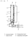
- a catalytic combustion apparatus is described by referring to its structural view in FIG. 1.
- a fuel supply valve 1 for controlling a supply amount of fuel gas and an air supply valve 2 for controlling a supply amount of air are provided, which are connected with a premixing chamber 3.
- a preheating burner 4 is located downstream of the premixing chamber 3
- a catalytic element 7 basically of a ceramic honeycomb in the shape of a plate with a large apparent surface area is placed downstream thereof, leading to an exhaust outlet 8.
- a radiated heat receiving plate 11 with heating medium channels 10 tightly adhered thereto is employed.
- a fuel gas supplied from the fuel supply valve 1 and air supplied from the air supply valve 2 are mixed in the premixing chamber 3, and fed to the preheating burner 4.
- a flame is formed in the preheating burner 4 by an ignition device 5 in the vicinity of the preheating burner 4, and the catalytic element 7 is increased in temperature by a hot exhaust gas produced by the flame.
- a heating medium is allowed to flow through a heating medium channel 16.
- supply of the fuel gas is temporarily discontinued by the fuel supply valve 1, and the flame is distinguished.
- catalytic combustion is initiated in the catalytic element 7.
- the heating medium receives a large quantity of heat, is increased in temperature, and comes to be hot, while it passes through the heating medium channel 10.
- the heating medium By using the heating medium, only specified object and place can be heated.
- hot-water supply system can be realized by directly using the heating medium as water, and the heating medium can also be used for floor heating by allowing it to flow through tubes arranged below a floor.
- the upstream surface of plate-like catalytic element 7 is heated to a temperature as high as 800°C to 850°C by combustion heat, and a large quantity of heat is radiated from the upstream surface of catalytic element 7. Because the radiated heat receiving plate 11 is located in a position opposing to the upstream surface of catalytic element 7, the radiated heat receiving plate receives the large quantity of radiation from the catalytic element 7. Since the heating medium channel 10 is tightly adhered to the radiated heat receiving plate 11, and the heating medium flows there through, a quantity of heat received by the radiated heat receiving plate 11 is conducted by thermal conduction to the heating medium, and the heating medium is increased in temperature.
- combustion heat is conducted to the heating medium without affecting the combusting condition of catalytic element.
- the radiated heat receiving plate 11 forming a heat receiving member is at a low temperature. As a result, a large quantity of combustion heat is radiated from the upstream surface of catalytic element 7, the temperature of upstream surface of the catalytic element 7 is reduced. Since the catalytic element 7 is at a high temperature in an upstream part during catalytic combustion, the highest temperature in the catalytic element 7 is lowered by the large quantity of heat radiation.
- a catalytic combustion apparatus according to a second embodiment of the invention is described by referring to its structural view in FIG. 2.
- the catalytic combustion apparatus according to the invention further comprises a radiated heat receiving plate 13 with heating medium channels 12 in a position opposite to a downstream surface of the catalytic element 7.
- downstream surface of catalytic element 7 is also at a high temperature during catalytic combustion, by providing the radiated heat receiving plate 13 in such position that it receives radiation from the downstream surface of catalytic element 7, heat radiated from the downstream surface of catalytic element 7 is also exchanged with a heating medium, and an efficiency of heat exchange in a catalytic combustion apparatus can be increased. Further, because of such heat exchange, since the temperature of downstream surface of the catalytic element 7 is reduced, that of upstream surface of the catalytic element 7 is also reduced. Therefore, the combustion capacity is further increased, and the size of a catalytic combustion apparatus can be further reduced.
- a catalytic combustion apparatus according to a third embodiment of the invention is described by referring to its structural view in FIG. 3.
- the catalytic combustion apparatus according to the embodiment comprises a first catalytic element 14 basically of a ceramic honeycomb plate and a second catalytic element 15 basically of a ceramic honeycomb plate downstream of the radiated heat receiving plate 13.
- the second catalytic element 15 is heated to a temperature at which it is active by a hot exhaust gas from the first catalytic element 14.
- a small quantity of unburned combustibles contained in a combustion gas from the first catalytic element 14 is completely combusted at the second catalytic element 15, and discharged from an exhaust outlet 8 as an exhaust gas containing no unburned combustible.
- an upstream surface of the second catalytic element 15 is also at a high temperature due to the combustion gas from the first catalytic element 14 and combustion heat in the second catalytic element 15, and heat is removed by radiation from the upstream surface of second catalytic element 15.
- the radiated heat receiving plate 13 is provided in the upstream side of second catalytic element 15, radiation from the upstream surface of second catalytic element 15 is received by the radiated heat receiving plate 13, and exchanged with the heating medium.
- a catalytic combustion apparatus according to a fourth embodiment of the invention is described by referring to its structural view in FIG. 4.
- the catalytic combustion apparatus according to the embodiment comprises a high-capacity radiation absorbing layer 16 with a black paint applied to an inner surface of the radiated heat receiving plate 11.
- the heat radiated from the upstream surface of catalytic element 7 can be surely received by the high-capacity radiation absorbing layer formed in an entire area in the upstream side of catalytic element 7, and exchanged with the heating medium.
- such additional layer having a high coefficient of radiation as above-described black paint coating and plating may be formed in a surface of the radiated heat receiving plate 11, or a coefficient of radiation may be increased by forming fine recesses and projections in a surface of the radiated heat receiving plate by such method as sand blasting.
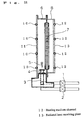
- a catalytic combustion apparatus according to a fifth embodiment of the invention is described by referring to its structural view in FIG. 5.
- the catalytic combustion apparatus according to the embodiment comprises a fuel supply valve 1 for controlling a supply amount of fuel gas and an air supply valve 2 for controlling a supply amount of air, which are connected with a premixing chamber 3.
- a preheating burner 4 is located downstream of the premixing chamber 3, leading to a combustion chamber 6.
- a catalytic element 7 consisting of a ceramic honeycomb that has multiple through-holes as a support and a radiated heat receiving plate 19 provided with copper tubes 17 that is tightly adhered thereto as first heating medium channels in positions opposite to an upstream surface 7a of the catalytic element 7 for allowing water to flow there through and a radiation absorbing layer 18 are placed.
- a copper tube 20 having multiple fins 21 is employed as second heating medium channels, and connected with the copper tubes 17.
- the outlet of combustion chamber 6 leads to an exhaust outlet 8.
- the fins 21 are attached to the copper tube 20 in such manner that a small spacing is formed between the fins 21 as an exhaust path 22.
- the fuel gas supplied from the fuel supply valve 1 and air supplied from the air supply valve 2 are mixed in the premixing chamber 3, and fed to the preheating burner 4.
- water is allowed to flow through the copper tubes 17 and 20.
- a flame is formed in the preheating burner 4 by an ignition device 5 in the vicinity of the preheating burner 4, and the catalytic element 7 is increased in temperature by a hot exhaust gas produced by the flame.
- the catalytic element 7 reaches a temperature at which it is active, supply of the fuel gas is temporarily discontinued by the fuel supply valve 1, and the flame is distinguished.
- catalytic combustion is initiated in the catalytic element 7.
- a hot exhaust gas discharged from the catalytic element 7 is discharged from the exhaust outlet 8 through the exhaust path 22.
- the upstream surface 7a of catalytic element 7 is at a temperature of 800°C to 850°C, and a downstream surface at 600°C to 750°C, thus a large quantity of heat is radiated from the upstream and downstream surfaces of catalytic element 7.
- the fins 13 are placed with a sufficiently small spacing between them, most radiation from the downstream surface of catalytic element 7 is directly received by the fins 21 or copper tube 20.
- the fins 21 are generally of copper, the coefficient of radiation is at 0.2 to 0.3.
- the radiated heat receiving plate 19 provided with the radiation absorbing layer 18 in an inner surface thereof and the copper tubes 17 tightly adhered thereto is employed in a position opposite to the upstream surface 7a of catalytic element 7, the heat radiated from the upstream surface 7a of catalytic element 7 is transmitted to the radiated heat receiving plate 19, and exchanged with water. It means that even the heat radiation reflected by the fins 21 and copper tube 20 is exchanged with water. Heat of the hot exhaust gas caused by the combustion heat in the catalytic element 7 is conducted by thermal conduction to the fins 21 and copper tube 20 as it passes through the exhaust path 22, and exchanged with water. As a result, because most heat radiated from the surface of catalytic element 7 is exchanged without being discharged to outside the catalytic combustion apparatus, a catalytic combustion apparatus providing a high efficiency of heat exchange can be realized.
- the fins 21 may be further elongated in the flowing direction, so that radiation from the downstream surface of catalytic element 7 can be almost fully directed to the copper tube and fins.
- the fins 21 may be only placed at least in positions opposite to respective ends of the catalytic element 7. It provides for solving such problem as described in connection with the prior art that the catalytic element comes to be lower in temperature in the vicinity of a catalytic element holder, the catalytic activity is locally reduced, and an exhaust gas containing unburned combustibles is discharged.
- the fins 21 are positioned in the direction perpendicular to the surface of catalytic element 7, the invention is not limited thereto, and the fins 21 may be positioned, for example, radially in relation with the surface of catalytic element 7 as shown in FIG. 8 (a). Alternatively, the fins 21 may be bent in the middle thereof, as shown in FIG. 8 (b).
- a catalytic combustion apparatus is described by referring to its structural view in FIG. 6.
- a radiation absorbing layer 23 is provided in surfaces of the fins 21 and copper tube 20.
- the surfaces of fins 21 and copper tube 20 may be coated with a thin layer of black paint having a high coefficient of radiation, or the coefficient of radiation may be increased by a blasting process or the like for roughing the surfaces.
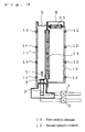
- a catalytic combustion apparatus according to a seventh embodiment of the invention is described by referring to its structural view in FIG. 7.
- a radiated heat receiving plate 19 with heating medium channels 17 is provided in a position opposite to an upstream surface of a catalytic element 7, and a heat exchanger 24 of fin-tube type allowing a heating medium to flow there through is located below the catalytic element 7.
- an exhaust gas discharged from the exhaust gas heat exchanger is adapted to be at a temperature not higher than a dew-point temperature in the exhaust gas heat exchanger.
- water in a combustion gas entering the heat exchanger 24 is condensed on a heat exchanging surface, when it exchanges heat on a surface of the heat exchanger 24.
- the pH value of condensed water in the combustion gas is at about 6 in the case of catalytic combustion, even if water is condensed on a surface of the heat exchanger, no problem is caused. Accordingly, when a combustion gas emitted by catalytic combustion is subjected to heat exchange by the heat exchanger 24, latent heat exchange can be also achieved in addition to conventional sensible heat exchange, an efficiency of heat exchange can be increased in comparison with conventional inflaming combustion method.
- a combustion gas caused in the catalytic element 7 is introduced to the heat exchanger 24, and discharged downward after heat exchange. Even when condensation of water is caused on the heat exchanger 24, since it drops downward, that is, in the discharging direction of the combustion gas according to the gravity, it never affects combustion in the catalytic element 7 which is above the heat exchanger 24. Thus, as a result of positive heat exchange in the heat exchanger 24, latent heat of H 2 O in the combustion gas can be also exchanged. In the upstream side of catalytic element 7, because the heat radiated from the upstream surface of catalytic element is exchanged by the radiated heat receiving plate 19, a catalytic combustion apparatus providing a very high efficiency of heat exchange as a whole can be achieved.
- a draining channel for collecting and draining condensed water may be provided below the heat exchanger 24 below the heat exchanger 24 below the heat exchanger 24 .
- an ignition device may be employed as igniting means in the downstream side of catalytic element (first catalytic element).
- first catalytic element a flame is formed in the downstream surface of catalytic element, and the catalytic element is increased in temperature by the flame.
- the catalytic combustion is naturally initiated, as soon as the catalytic element reaches a temperature at which it is active, since an exhaust gas caused by the catalytic combustion is simultaneously applied to the flame in the downstream side of catalytic element, the flame is distinguished. Therefore, by providing an ignition device in the downstream side of catalytic element, natural shift from inflaming combustion for preheating to catalytic combustion can be achieved without controlling a fuel supply.
- a ceramic heater may be used for heating a premixed gas locally to an ignition temperature or a higher temperature, or an igniter may be employed for applying a spark to a frame of the catalytic element or a wall of the catalytic combustion apparatus.
- a catalytic combustion apparatus providing a high efficiency of heat exchange can be achieved in a compact size by using a catalytic element in the shape of a plate, and allowing a radiated heat receiving plate with heating medium channels to receive a large quantity of heat radiated from a surface of the catalytic element for heat exchange with the heating medium.
Landscapes
- Engineering & Computer Science (AREA)
- Chemical & Material Sciences (AREA)
- Combustion & Propulsion (AREA)
- Mechanical Engineering (AREA)
- General Engineering & Computer Science (AREA)
- Chemical Kinetics & Catalysis (AREA)
- Physics & Mathematics (AREA)
- Thermal Sciences (AREA)
- Gas Burners (AREA)
Abstract
Description
- The present invention relates to a catalytic combustion apparatus superior in characteristics of an exhaust gas for catalytically combusting a gaseous fuel or liquid fuel that is vaporized, and utilizing the combustion heat and exhaust gas for such applications as heating, air heating and drying.
- Conventionally, a catalytic combustion apparatus for catalytically combusting a gaseous or liquid fuel for heating, air heating and drying has been generally constituted as shown in FIG. 9.
- By using FIG. 9, the constitution is described. In FIG. 9, a fuel gas supplied from a
fuel supply valve 1 is mixed in apremixing chamber 3 with air supplied from anair supply valve 2, and sent to a preheatingburner 4 as a premixed gas. It is ignited by anignition device 5, and forms a flame at the preheatingburner 4. An exhaust gas of a high temperature caused by the flame heats acatalytic element 7 provided in a combustion chamber, passes there through, and is discharged from anoutlet 8. When thecatalytic element 7 is heated to a temperature at which it is active, supply of the fuel is temporarily discontinued by thefuel supply valve 1, and the flame is distinguished. By restarting supply of the fuel immediately after that, catalytic combustion is initiated. The catalytic element reaches a high temperature, and emits heat radiantly through aglass 9 that is located in a position opposite to an upstream surface of the catalytic element as well as in the form of a hot exhaust gas from theoutlet 8 for heating and air heating applications. - Because the catalytic combustion is surface combustion, a large quantity of radiation is emitted from the catalytic element in correspondence with a temperature of the catalytic element and an apparent surface area of the catalytic element. In a catalytic combustion apparatus for heating and air heating by means of heat exchange using a heating medium, combustion heat generated on the catalytic element must be efficiently exchanged with the heating medium. It is, therefore, required that a radiation from a surface of the catalytic element is effectively exchanged. However, it has been a problem that an efficiency of heat exchange of a catalytic combustion apparatus is reduced correspondingly, if heat radiated from the catalytic element, instead of being conducted to a heat exchanger, is applied to other outer wall of the combustion apparatus, or emitted outside the combustion apparatus.
- Thus, in order to solve the problem, the invention intends to realize a catalytic combustion apparatus effectively utilizing a radiation from a surface of catalytic element for providing a high efficiency of heat exchange.
- Further, in the case a catalytic element is employed in a combustion chamber, combustion heat on the catalytic element is conducted by thermal conduction to the combustion chamber from an attachment part to the combustion chamber. Therefore, it has been a problem that the catalytic element is lower in temperature in the vicinity of a catalytic element holder, the catalytic activity is locally reduced, and an exhaust gas containing unburned combustibles is emitted.
- Hence, it is an object of the invention to prevent emission of unburned combustibles from an attachment part of catalytic element to a combustion chamber, and provide a catalytic combustion apparatus superior in characteristics of an exhaust gas.
- In addition, in the case sensible heat of a combustion gas is exchanged by means of such heat exchanger as a fin-tube type, when the heat exchanger is placed above a catalytic element, because combustion heat is used for raising the temperature of the combustion apparatus itself at the time of startup of the combustion apparatus, and the temperature of an exhaust gas cannot be very high, condensation is caused on the heat exchanger, and the catalytic element may be wetted. If the catalytic element is wetted by the condensed water, the temperature is reduced, the catalytic activity is lowered, and the reactivity may be locally reduced. Also, as condensation on the heat exchanger should not be allowed, positive heat exchange was unachievable, and it was forced that the latent heat in the combustion gas be discharged as an exhaust loss instead of being collected.
- Thus, in order to solve the problem, the invention intends to prevent combustion characteristics from being locally affected by condensed water, and allow stable combustion to be maintained by providing a heat exchanger above a heat exchanger, and discharging water condensed on the heat exchanger to outside a combustion apparatus. The invention also intends to realize a catalytic combustion apparatus providing a very high efficiency of heat exchange by collecting latent heat in a combustion gas at the same time.
- The invention provides, as defined in
claim 1, a catalytic combustion apparatus comprising a fuel supply member for supplying a fuel, an air supply member for supplying combustion air, a premixing chamber for mixing the fuel supplied from the fuel supply member and the air supplied from the air supply member to make a mixed gas, a catalytic element in the shape of a plate consisting of a porous member for catalytically combusting the mixed gas and a combustion chamber provided in a downstream side of the premixing chamber, containing the catalytic element in the shape of a plate, and incorporating a first radiated heat receiving member that is positioned opposite to either one of two surfaces of the catalytic element as a part of its side wall. - The first radiated heat receiving member may have a heating medium channel tightly adhered thereto or incorporated therein.
- The combustion chamber may incorporate a second radiated heat receiving member that is positioned opposite to the other of two surfaces of the catalytic element as a part of its side wall.
- The second radiated heat receiving member may have a heating medium channel tightly adhered thereto or incorporated therein.
- In an outlet of the combustion chamber, a second catalytic element in the shape of a plate consisting of a porous member may be provided.
- A radiation absorbing layer may be employed in a surface of the first radiated heat receiving member inside the combustion chamber.
- A radiation absorbing layer may be provided in a surface of the second radiated heat receiving member inside the combustion chamber.
- The catalytic combustion apparatus further comprises a heat exchanging member provided in a downstream side of the combustion chamber, wherein the combustion chamber may be located above the heat exchanging member.
- The invention provides, as defined in
claim 9, a catalytic combustion apparatus comprising a catalytic element with multiple through-holes for combusting a mixed gas of a fuel and air, a combustion chamber containing the catalytic element, and having a radiated heat receiving member that is positioned opposite to an upstream side of the catalytic element in the flowing direction of the mixed gas, a first heating medium channel provided in the radiated heat receiving plate, a second heating medium channel located downstream of the catalytic element in the flowing direction, and having multiple fins and an exhaust path formed between the fins, wherein the multiple fins are placed at least in a position opposite to either end of the catalytic element. - According to such constitution, by reducing a spacing between the fins, and Increasing a length in the flowing direction, for example, radiation from a downstream surface of the heating medium is almost fully directed to the fins and the second heating medium channel.
- Now, operation of the invention is described below by way of example.
- Generally, in a catalytic combustion apparatus, combustion is conducted in such condition that an upstream portion of catalytic element is at the highest temperature, and a large quantity of heat radiated from the upstream surface at the high temperature of catalytic element is made use of.
- Thus, by using a catalytic element in the shape of a plate that provides a large apparent surface area, and employing a radiated heat receiving member in a position opposite to the catalytic element, the large quantity of heat radiation conducted from the surface of catalytic element can be received by the radiated heat receiving member. Since the radiated heat receiving member receiving the heat has a channel for passing a heating medium tightly adhered thereto or incorporated therein, the heat is conducted to the channel for passing the heating medium, and further exchanged with the heating medium in the channel.
- Now, because the heat is conducted to the radiated heat receiving member by radiative conduction, the heat is evenly removed from the entire catalytic element. Therefore, since unevenness in temperature caused as the combustion heat is removed by direct thermal conduction from a part of the catalytic element is prevented, the large quantity of combustion heat on the catalytic element can be transferred to the heating medium, while stable combustion is maintained. In addition, because the temperature of upstream surface of the catalytic element that is at the highest temperature is reduced by positive heat exchange with the radiated heat receiving member, a higher combustion capacity can be achieved without increasing the temperature of catalytic element to a limit of its heat resistance. As a result, a compact catalytic combustion apparatus using a heating medium for heat exchange can be realized.
- Further, by providing the first and second radiated heat receiving members in opposition to respective surfaces of the plate-like catalytic element, because radiation from both surfaces of the catalytic element can be captured by the first and second radiated heat receiving members for heat exchange, and outer surfaces of the catalytic element are simultaneously formed by the first and second radiated heat receiving members, outer surfaces of the catalytic combustion apparatus can be maintained at a low temperature. As a result, radiation loss due to removal of heat by natural convection and radiation from the outer surfaces of catalytic combustion apparatus can be reduced, and an efficiency of heat exchange can be increased.
- As heat is removed from the catalytic element to the second radiated heat receiving member, because the temperature of catalytic element is reduced in the opposite side thereof, and the temperature of catalytic element in a side opposite to the first radiated heat receiving member is also reduced due to thermal conduction within the catalytic element, the combustion capacity is further increased. Therefore, a catalytic combustion apparatus providing a high efficiency of heat exchange can be realized in a more compact size.
- By providing the second catalytic element in a downstream side of the combustion chamber, since heat radiation from the second catalytic element can be also received by the radiated heat receiving member, an efficiency of heat exchange in the catalytic combustion apparatus can be further increased. Simultaneously, a small quantity of unburned combustibles discharged from the first catalytic element is combusted, and a catalytic combustion apparatus superior in characteristics of an exhaust gas can be achieved.
- Further, by providing a radiation absorbing layer in a surface of the radiated heat receiving member, since radiation from a surface of the catalytic element can be very efficiently received by the radiated heat receiving member, an efficiency of heat exchange can be further increased.
- By placing the catalytic element above a heat exchanging member for collecting sensible heat in a combustion gas that is produced in the catalytic element, even if condensation of water is caused on the heat exchanging member due to any condition, the water condensed is discharged to outside the combustion apparatus, moving downward from the heat exchanging member in the discharging direction of exhaust gas.
- Thus, combusting conditions cannot be affected due to wetting of the catalytic element, and stable combustion can be maintained. Now, although the pH value of water condensed is at 3 or a lower value in the case of inflaming combustion, because NOx is contained in a combustion gas, almost no NOx is contained in the case of catalytic combustion, and no other substance is, therefore, contained in the water condensed except such soluble contents as CO2 and H2O in a combustion gas. Thus, the pH value is at 6, and corrosion of the heat exchanger by the water condensed can be prevented.
- Accordingly, as latent heat in a combustion gas can be collected by positive heat exchange, a catalytic combustion apparatus very high in efficiency of heat exchange can be realized.
- FIG. 1 is a structural view of a catalytic combustion apparatus according to a first embodiment of the invention.
- FIG. 2 is a structural view of a catalytic combustion apparatus according to a second embodiment of the invention.
- FIG. 3 is a structural view of a catalytic combustion apparatus according to a third embodiment of the invention.
- FIG. 4 is a structural view of a catalytic combustion apparatus according to a fourth embodiment of the invention.
- FIG. 5 is a structural view of a catalytic combustion apparatus according to a fifth embodiment of the invention.
- FIG. 6 is a structural view of a catalytic combustion apparatus according to a sixth embodiment of the invention.
- FIG. 7 is a structural view of a catalytic combustion apparatus according to a seventh embodiment of the invention.
- FIG. 8 is a view of a catalytic combustion apparatus according to the fifth embodiment, showing another example of attachment of fins.
- FIG. 9 is a structural view of a conventional catalytic combustion apparatus.
-
- 7
- Catalytic element
- 10
- Heating medium channel
- 11
- Radiated heat receiving plate
- 12
- Heating medium channel
- 13
- Radiated heat receiving plate
- 14
- First catalytic element
- 15
- Second catalytic element
- 16
- High-capacity radiation absorbing layer
- 17
- Copper tube
- 18
- Radiation absorbing layer
- 19
- Radiated heat receiving plate
- 20
- Copper tube
- 21
- Fin
- 22
- Exhaust path
- 23
- Radiation absorbing layer
- 24
- Heat exchanger
- Embodiments of the invention is described below by referring to the drawings.
- A catalytic combustion apparatus according to a first embodiment of the invention is described by referring to its structural view in FIG. 1. A
fuel supply valve 1 for controlling a supply amount of fuel gas and anair supply valve 2 for controlling a supply amount of air are provided, which are connected with apremixing chamber 3. Apreheating burner 4 is located downstream of thepremixing chamber 3, acatalytic element 7 basically of a ceramic honeycomb in the shape of a plate with a large apparent surface area is placed downstream thereof, leading to anexhaust outlet 8. In a position opposing to an upstream surface of thecatalytic element 7, a radiatedheat receiving plate 11 withheating medium channels 10 tightly adhered thereto is employed. - In such construction, a fuel gas supplied from the
fuel supply valve 1 and air supplied from theair supply valve 2 are mixed in thepremixing chamber 3, and fed to thepreheating burner 4. A flame is formed in thepreheating burner 4 by anignition device 5 in the vicinity of thepreheating burner 4, and thecatalytic element 7 is increased in temperature by a hot exhaust gas produced by the flame. Meantime, a heating medium is allowed to flow through a heating medium channel 16. As soon as thecatalytic element 7 reaches a temperature at which it is active, supply of the fuel gas is temporarily discontinued by thefuel supply valve 1, and the flame is distinguished. As the fuel is supplied by thefuel supply valve 1 immediately after that, catalytic combustion is initiated in thecatalytic element 7. - The heating medium receives a large quantity of heat, is increased in temperature, and comes to be hot, while it passes through the
heating medium channel 10. By using the heating medium, only specified object and place can be heated. For example, hot-water supply system can be realized by directly using the heating medium as water, and the heating medium can also be used for floor heating by allowing it to flow through tubes arranged below a floor. - During catalytic combustion, the upstream surface of plate-like
catalytic element 7 is heated to a temperature as high as 800°C to 850°C by combustion heat, and a large quantity of heat is radiated from the upstream surface ofcatalytic element 7. Because the radiatedheat receiving plate 11 is located in a position opposing to the upstream surface ofcatalytic element 7, the radiated heat receiving plate receives the large quantity of radiation from thecatalytic element 7. Since theheating medium channel 10 is tightly adhered to the radiatedheat receiving plate 11, and the heating medium flows there through, a quantity of heat received by the radiatedheat receiving plate 11 is conducted by thermal conduction to the heating medium, and the heating medium is increased in temperature. - Now, according to the structure, because conduction of heat from the
catalyst 7 to the radiatedheat receiving plate 11 is achieved by radiation, heat is evenly removed from an entire surface of thecatalytic element 7, and the surface ofcatalytic element 7 is uniform in temperature, even though a large quantity of heat is removed. If the heat from thecatalytic element 7 is conducted directly by thermal conduction, the temperature of catalyst is reduced in the vicinity of a part from which the heat is removed, unevenness in temperature is caused on thecatalytic element 7, and combustion may possibly be unstable. - Thus, by using the radiated
heat receiving plate 11, combustion heat is conducted to the heating medium without affecting the combusting condition of catalytic element. - Because most of the heat radiated from the upstream surface of
catalytic element 7 is conducted to the heating medium as described above, the radiatedheat receiving plate 11 forming a heat receiving member is at a low temperature. As a result, a large quantity of combustion heat is radiated from the upstream surface ofcatalytic element 7, the temperature of upstream surface of thecatalytic element 7 is reduced. Since thecatalytic element 7 is at a high temperature in an upstream part during catalytic combustion, the highest temperature in thecatalytic element 7 is lowered by the large quantity of heat radiation. - Therefore, even if a combustion capacity is increased, because the
catalytic element 7 is unlikely heated to a temperature limit of its heat resistance, a combustion capacity can be increased, and a catalytic combustion apparatus compact in relation to the combustion capacity can be realized. - A catalytic combustion apparatus according to a second embodiment of the invention is described by referring to its structural view in FIG. 2. The catalytic combustion apparatus according to the invention further comprises a radiated heat receiving plate 13 with
heating medium channels 12 in a position opposite to a downstream surface of thecatalytic element 7. - Because the downstream surface of
catalytic element 7 is also at a high temperature during catalytic combustion, by providing the radiated heat receiving plate 13 in such position that it receives radiation from the downstream surface ofcatalytic element 7, heat radiated from the downstream surface ofcatalytic element 7 is also exchanged with a heating medium, and an efficiency of heat exchange in a catalytic combustion apparatus can be increased. Further, because of such heat exchange, since the temperature of downstream surface of thecatalytic element 7 is reduced, that of upstream surface of thecatalytic element 7 is also reduced. Therefore, the combustion capacity is further increased, and the size of a catalytic combustion apparatus can be further reduced. - Since the radiated
heat receiving plates 11 and 13 form walls of acombustion chamber 6, and most of combustion heat in thecatalytic element 7 is exchanged with the heating medium, increase in temperature of the walls ofcombustion chamber 6 is restricted. Therefore, as almost no radiation loss is caused due to thermal conduction by natural convection and radiation from walls of the catalytic combustion apparatus, an efficiency of heat exchange comes to be high. - A catalytic combustion apparatus according to a third embodiment of the invention is described by referring to its structural view in FIG. 3. The catalytic combustion apparatus according to the embodiment comprises a first
catalytic element 14 basically of a ceramic honeycomb plate and a second catalytic element 15 basically of a ceramic honeycomb plate downstream of the radiated heat receiving plate 13. - During catalytic combustion, the second catalytic element 15 is heated to a temperature at which it is active by a hot exhaust gas from the first
catalytic element 14. Thus, a small quantity of unburned combustibles contained in a combustion gas from the firstcatalytic element 14 is completely combusted at the second catalytic element 15, and discharged from anexhaust outlet 8 as an exhaust gas containing no unburned combustible. - In such operation, an upstream surface of the second catalytic element 15 is also at a high temperature due to the combustion gas from the first
catalytic element 14 and combustion heat in the second catalytic element 15, and heat is removed by radiation from the upstream surface of second catalytic element 15. - However, because the radiated heat receiving plate 13 is provided in the upstream side of second catalytic element 15, radiation from the upstream surface of second catalytic element 15 is received by the radiated heat receiving plate 13, and exchanged with the heating medium.
- As a result, since the heat radiated from the upstream and downstream surfaces of first
catalytic element 14 as well as the upstream surface of second catalytic element 15 is exchanged with the heating medium, a catalytic combustion apparatus providing a very high efficiency of heat exchange can be realized. - A catalytic combustion apparatus according to a fourth embodiment of the invention is described by referring to its structural view in FIG. 4. The catalytic combustion apparatus according to the embodiment comprises a high-capacity radiation absorbing layer 16 with a black paint applied to an inner surface of the radiated
heat receiving plate 11. - As a coefficient of radiation of the black paint is at 0.9 to 1.0, radiation from the upstream surface of
catalytic element 7 is very efficiently received by the high-capacity radiation absorbing layer 16, conducted to the radiatedheat receiving plate 11, and exchanged with the heating medium. Thus, an efficiency of heat exchange can be increased. Because of a higher efficiency of heat exchange, a quantity of heat conducted from the upstream surface ofcatalytic element 7 to the radiatedheat receiving plate 11, that is, a quantity of heat removed from the upstream surface ofcatalytic element 7 is increased, and the temperature of upstream surface of thecatalytic element 7 is reduced. - As a result, since a higher combustion capacity can be obtained at a temperature below a limit of the heat resistance, the size of a catalytic combustion apparatus can be reduced.
- By providing a high-capacity radiation absorbing layer in an inner surface of the
combustion chamber 6 in addition to the radiatedheat receiving plate 11, and increasing thermal conduction to the radiatedheat receiving plate 11, the heat radiated from the upstream surface ofcatalytic element 7 can be surely received by the high-capacity radiation absorbing layer formed in an entire area in the upstream side ofcatalytic element 7, and exchanged with the heating medium. - As for the high-capacity radiation absorbing layer 16, such additional layer having a high coefficient of radiation as above-described black paint coating and plating may be formed in a surface of the radiated
heat receiving plate 11, or a coefficient of radiation may be increased by forming fine recesses and projections in a surface of the radiated heat receiving plate by such method as sand blasting. - In the first to fourth embodiments, by providing such heat exchanger as a fin-tube type downstream of the
catalytic element 7 or second catalytic element 15 for collecting latent heat in the exhaust gas, and allowing a heating medium to flow there through for exhaust heat recovery, the efficiency of heat exchange can be further increased. - A catalytic combustion apparatus according to a fifth embodiment of the invention is described by referring to its structural view in FIG. 5. The catalytic combustion apparatus according to the embodiment comprises a
fuel supply valve 1 for controlling a supply amount of fuel gas and anair supply valve 2 for controlling a supply amount of air, which are connected with apremixing chamber 3. Apreheating burner 4 is located downstream of thepremixing chamber 3, leading to acombustion chamber 6. In thecombustion chamber 6, acatalytic element 7 consisting of a ceramic honeycomb that has multiple through-holes as a support and a radiatedheat receiving plate 19 provided withcopper tubes 17 that is tightly adhered thereto as first heating medium channels in positions opposite to anupstream surface 7a of thecatalytic element 7 for allowing water to flow there through and aradiation absorbing layer 18 are placed. In addition, at an outlet of thecombustion chamber 6, acopper tube 20 havingmultiple fins 21 is employed as second heating medium channels, and connected with thecopper tubes 17. The outlet ofcombustion chamber 6 leads to anexhaust outlet 8. Thefins 21 are attached to thecopper tube 20 in such manner that a small spacing is formed between thefins 21 as anexhaust path 22. - In such construction, the fuel gas supplied from the
fuel supply valve 1 and air supplied from theair supply valve 2 are mixed in thepremixing chamber 3, and fed to thepreheating burner 4. Meantime, water is allowed to flow through thecopper tubes preheating burner 4 by anignition device 5 in the vicinity of thepreheating burner 4, and thecatalytic element 7 is increased in temperature by a hot exhaust gas produced by the flame. As soon as thecatalytic element 7 reaches a temperature at which it is active, supply of the fuel gas is temporarily discontinued by thefuel supply valve 1, and the flame is distinguished. As the fuel is supplied by thefuel supply valve 1 immediately after that, catalytic combustion is initiated in thecatalytic element 7. A hot exhaust gas discharged from thecatalytic element 7 is discharged from theexhaust outlet 8 through theexhaust path 22. - During steady combustion, the
upstream surface 7a ofcatalytic element 7 is at a temperature of 800°C to 850°C, and a downstream surface at 600°C to 750°C, thus a large quantity of heat is radiated from the upstream and downstream surfaces ofcatalytic element 7. According to the embodiment, because the fins 13 are placed with a sufficiently small spacing between them, most radiation from the downstream surface ofcatalytic element 7 is directly received by thefins 21 orcopper tube 20. Now, since thefins 21 are generally of copper, the coefficient of radiation is at 0.2 to 0.3. Therefore, although a part of the radiation is conducted to thefins 21 andcopper tube 20, and the heat is exchanged with water, still other part is reflected by a surface of thefins 21 andcopper tube 20, and directed to the downstream surface ofcatalytic element 7. If it is directed to the downstream surface ofcatalytic element 7, as thermal conduction to the downstream side within thecatalytic element 7 is disturbed, the entirecatalytic element 7 is increased in temperature. Accordingly, theupstream surface 7a ofcatalytic element 7 already at a high temperature is further increased in temperature, and a large quantity of radiation is caused from theupstream surface 7a ofcatalytic element 7. Since the radiatedheat receiving plate 19 provided with theradiation absorbing layer 18 in an inner surface thereof and thecopper tubes 17 tightly adhered thereto is employed in a position opposite to theupstream surface 7a ofcatalytic element 7, the heat radiated from theupstream surface 7a ofcatalytic element 7 is transmitted to the radiatedheat receiving plate 19, and exchanged with water. It means that even the heat radiation reflected by thefins 21 andcopper tube 20 is exchanged with water. Heat of the hot exhaust gas caused by the combustion heat in thecatalytic element 7 is conducted by thermal conduction to thefins 21 andcopper tube 20 as it passes through theexhaust path 22, and exchanged with water. As a result, because most heat radiated from the surface ofcatalytic element 7 is exchanged without being discharged to outside the catalytic combustion apparatus, a catalytic combustion apparatus providing a high efficiency of heat exchange can be realized. - The
fins 21 may be further elongated in the flowing direction, so that radiation from the downstream surface ofcatalytic element 7 can be almost fully directed to the copper tube and fins. - Alternatively, the
fins 21 may be only placed at least in positions opposite to respective ends of thecatalytic element 7. It provides for solving such problem as described in connection with the prior art that the catalytic element comes to be lower in temperature in the vicinity of a catalytic element holder, the catalytic activity is locally reduced, and an exhaust gas containing unburned combustibles is discharged. - In the first embodiment, although the
fins 21 are positioned in the direction perpendicular to the surface ofcatalytic element 7, the invention is not limited thereto, and thefins 21 may be positioned, for example, radially in relation with the surface ofcatalytic element 7 as shown in FIG. 8 (a). Alternatively, thefins 21 may be bent in the middle thereof, as shown in FIG. 8 (b). - A catalytic combustion apparatus according to a sixth embodiment of the invention is described by referring to its structural view in FIG. 6. In addition to the components of
above embodiment 5, aradiation absorbing layer 23 is provided in surfaces of thefins 21 andcopper tube 20. - In the embodiment, radiation of heat directed from the downstream surface of
catalytic element 7 to thefins 21 andcopper tube 20 is efficiently absorbed by theradiation absorbing layer 23, and the heat is exchanged with water. Therefore, because the radiation of heat from the downstream surface ofcatalytic element 7 is almost fully absorbed by thefins 21 andcopper tube 20, and exchanged, a catalytic combustion apparatus providing a high efficiency of heat exchange can be realized. - As for the
radiation absorbing layer 23, the surfaces offins 21 andcopper tube 20 may be coated with a thin layer of black paint having a high coefficient of radiation, or the coefficient of radiation may be increased by a blasting process or the like for roughing the surfaces. - A catalytic combustion apparatus according to a seventh embodiment of the invention is described by referring to its structural view in FIG. 7. A radiated
heat receiving plate 19 withheating medium channels 17 is provided in a position opposite to an upstream surface of acatalytic element 7, and a heat exchanger 24 of fin-tube type allowing a heating medium to flow there through is located below thecatalytic element 7. - It is known that almost no NOx is contained in an exhaust gas caused by catalytic combustion. Therefore, when an exhaust gas is condensed, the pH value of condensed water is lower than 3 in the case of inflaming combustion, while the pH value of about 6 is found in the case of catalytic combustion, because the condensed water contain almost no nitric acid. As a result, even when water contained in a combustion gas is condensed on a surface of the heat exchanger 24, corrosion in the surface of heat exchanger is never caused by the condensed water in the case of catalytic combustion.
- It is positively made use of in the catalytic combustion apparatus according to the embodiment, and an exhaust gas discharged from the exhaust gas heat exchanger is adapted to be at a temperature not higher than a dew-point temperature in the exhaust gas heat exchanger. By means of such arrangement, water in a combustion gas entering the heat exchanger 24 is condensed on a heat exchanging surface, when it exchanges heat on a surface of the heat exchanger 24. As described above, because the pH value of condensed water in the combustion gas is at about 6 in the case of catalytic combustion, even if water is condensed on a surface of the heat exchanger, no problem is caused. Accordingly, when a combustion gas emitted by catalytic combustion is subjected to heat exchange by the heat exchanger 24, latent heat exchange can be also achieved in addition to conventional sensible heat exchange, an efficiency of heat exchange can be increased in comparison with conventional inflaming combustion method.
- An operation of a catalytic combustion apparatus providing above-mentioned effects is described by referring to FIG. 7.
- A combustion gas caused in the
catalytic element 7 is introduced to the heat exchanger 24, and discharged downward after heat exchange. Even when condensation of water is caused on the heat exchanger 24, since it drops downward, that is, in the discharging direction of the combustion gas according to the gravity, it never affects combustion in thecatalytic element 7 which is above the heat exchanger 24. Thus, as a result of positive heat exchange in the heat exchanger 24, latent heat of H2O in the combustion gas can be also exchanged. In the upstream side ofcatalytic element 7, because the heat radiated from the upstream surface of catalytic element is exchanged by the radiatedheat receiving plate 19, a catalytic combustion apparatus providing a very high efficiency of heat exchange as a whole can be achieved. - Below the heat exchanger 24, a draining channel for collecting and draining condensed water may be provided.
- In the first to seventh embodiments, an ignition device may be employed as igniting means in the downstream side of catalytic element (first catalytic element). In such case, upon ignition, a flame is formed in the downstream surface of catalytic element, and the catalytic element is increased in temperature by the flame. Although the catalytic combustion is naturally initiated, as soon as the catalytic element reaches a temperature at which it is active, since an exhaust gas caused by the catalytic combustion is simultaneously applied to the flame in the downstream side of catalytic element, the flame is distinguished. Therefore, by providing an ignition device in the downstream side of catalytic element, natural shift from inflaming combustion for preheating to catalytic combustion can be achieved without controlling a fuel supply. As an ignition device, a ceramic heater may be used for heating a premixed gas locally to an ignition temperature or a higher temperature, or an igniter may be employed for applying a spark to a frame of the catalytic element or a wall of the catalytic combustion apparatus.
- As clearly shown in above description, according to the invention, a catalytic combustion apparatus providing a high efficiency of heat exchange can be achieved in a compact size by using a catalytic element in the shape of a plate, and allowing a radiated heat receiving plate with heating medium channels to receive a large quantity of heat radiated from a surface of the catalytic element for heat exchange with the heating medium.
- Further, by directing a full quantity of radiation from a downstream surface of the catalytic element to the heating medium channels, a catalytic combustion apparatus providing even higher efficiency of heat exchange can be realized.
- Also, because stable combustion can be maintained even when condensation of water is caused, by placing the catalytic element above a heat exchanger, and latent heat of H2O in a combustion gas can be also collected by the heat exchanger because of positive heat exchange, a catalytic combustion apparatus providing a very high efficiency of heat exchange can be achieved.
Claims (12)
- A catalytic combustion apparatus comprising:a fuel supply member for supplying a fuel;an air supply member for supplying air;a premixing chamber for mixing the fuel supplied from the fuel supply member and the air supplied from the air supply member to make a mixed gas;a catalytic element in the shape of a plate consisting of a porous member for catalytically combusting the mixed gas; anda combustion chamber provided in a downstream side of the premixing chamber, accommodating the catalytic element in the shape of a plate, and incorporating a first radiated heat receiving member that is positioned opposite to at least one of two surfaces of the catalytic element as a part of its side wall.
- A catalytic combustion apparatus according to claim 2, wherein the first radiated heat receiving member is provided with heating medium channels tightly adhered thereto or incorporated therein.
- A catalytic combustion apparatus according to claim 2, wherein the combustion chamber incorporates a second radiated heat receiving member that is positioned opposite to the other of two surfaces of the catalytic element as a part of its side walls.
- A catalytic combustion apparatus according to claim 3, wherein the second radiated heat receiving member is provided with heating medium channels tightly adhered thereto or incorporated therein.
- A catalytic combustion apparatus according to claim 3 or 4, wherein a second catalytic element in the shape of a plate consisting of a porous member is employed at an out let of the combustion chamber.
- A catalytic combustion apparatus according to any of claim 1 to 5, wherein a radiation absorbing layer is provided in a surface of the first radiated heat receiving member within the combustion chamber.
- A catalytic combustion apparatus according to claim 3, 4 or 5, wherein a radiation absorbing layer is provided in a surface of the second radiated heat receiving member within the combustion chamber.
- A catalytic combustion apparatus according to claim 1 or 2 further comprising a heat exchanging member that is provided in a downstream side of the combustion chamber, wherein the combustion chamber is located above the heat exchanging member.
- A catalytic combustion apparatus comprising:a catalytic element having multiple through-holes for combusting a mixed gas of a fuel and air;a combustion chamber accommodating the catalytic element, and having a radiated heat receiving member located in opposition to a surface of the catalytic member in a upstream side thereof in the flowing direction of the mixed gas;first heating medium channels provided in the radiated heat receiving plate;a second heating medium channel located downstream in the flowing direction of the catalytic element, and having multiple fins; andexhaust paths formed between the fins,
wherein the multiple fins are placed at least in a position opposite to respective ends of the catalytic element. - A catalytic combustion apparatus according to claim 9, wherein the fins are positioned at an angle to a surface of the catalytic element.
- A catalytic combustion apparatus according to claim 9 or 10, wherein a radiation absorbing layer is provided in surfaces of the heating medium channels and fins.
- A catalytic combustion apparatus comprising:a fuel supply member for supplying a fuel;an air supply member for supplying air;a premixing chamber for mixing the fuel supplied from the fuel supply member and the air supplied from the air supply member to make a mixed gas;a catalytic element for catalytically combusting the mixed gas;a combustion chamber accommodating the catalytic element; anda heat exchanging member placed in a downstream side of the combustion chamber,
wherein an exhaust gas discharged from the heat exchanging member is at a temperature not higher than a dew-point temperature of the heat exchanger.
Applications Claiming Priority (7)
| Application Number | Priority Date | Filing Date | Title |
|---|---|---|---|
| JP32610095 | 1995-12-14 | ||
| JP326100/95 | 1995-12-14 | ||
| JP32610095 | 1995-12-14 | ||
| JP9786696 | 1996-04-19 | ||
| JP97866/96 | 1996-04-19 | ||
| JP9786696 | 1996-04-19 | ||
| PCT/JP1996/003582 WO1997021957A1 (en) | 1995-12-14 | 1996-12-06 | Catalytic combustion apparatus |
Publications (3)
| Publication Number | Publication Date |
|---|---|
| EP0807786A1 true EP0807786A1 (en) | 1997-11-19 |
| EP0807786A4 EP0807786A4 (en) | 1999-08-04 |
| EP0807786B1 EP0807786B1 (en) | 2003-04-09 |
Family
ID=26439004
Family Applications (1)
| Application Number | Title | Priority Date | Filing Date |
|---|---|---|---|
| EP96941194A Expired - Lifetime EP0807786B1 (en) | 1995-12-14 | 1996-12-06 | Catalytic combustion apparatus |
Country Status (7)
| Country | Link |
|---|---|
| US (1) | US6431856B1 (en) |
| EP (1) | EP0807786B1 (en) |
| JP (1) | JP3568964B2 (en) |
| KR (1) | KR100452835B1 (en) |
| CN (1) | CN1105869C (en) |
| DE (1) | DE69627313T2 (en) |
| WO (1) | WO1997021957A1 (en) |
Cited By (3)
| Publication number | Priority date | Publication date | Assignee | Title |
|---|---|---|---|---|
| WO1998046947A1 (en) * | 1997-04-16 | 1998-10-22 | Rossteuscher Andreas P | Heat engine |
| EP0789188A3 (en) * | 1996-02-06 | 1999-01-27 | Fraunhofer-Gesellschaft Zur Förderung Der Angewandten Forschung E.V. | Catalytic burner |
| EP0962697A3 (en) * | 1998-06-05 | 2000-06-07 | Matsushita Electric Industrial Co., Ltd. | Catalytic combustion system and combustion control method |
Families Citing this family (23)
| Publication number | Priority date | Publication date | Assignee | Title |
|---|---|---|---|---|
| JP3466103B2 (en) * | 1999-03-16 | 2003-11-10 | 松下電器産業株式会社 | Catalytic combustion device |
| US7138093B2 (en) * | 2003-07-08 | 2006-11-21 | Mckay Randy | Heat exchanger device |
| US20070278199A1 (en) * | 2006-04-14 | 2007-12-06 | Ewa Environmental, Inc. | Particle burning in an exhaust system |
| JP2007322019A (en) * | 2006-05-30 | 2007-12-13 | Nippon Chem Plant Consultant:Kk | Combustor |
| US7578669B2 (en) * | 2006-12-14 | 2009-08-25 | Texaco Inc. | Hybrid combustor for fuel processing applications |
| CN101149147B (en) * | 2007-11-05 | 2010-04-07 | 中南大学 | Totally-premixed natural gas catalytic combustion device dispersed combustion method |
| KR20090067760A (en) * | 2007-12-21 | 2009-06-25 | 주식회사 경동나비엔 | Heat exchanger of upward conbustion type condensing boiler |
| US9166139B2 (en) | 2009-05-14 | 2015-10-20 | The Neothermal Energy Company | Method for thermally cycling an object including a polarizable material |
| US8344585B2 (en) | 2009-05-14 | 2013-01-01 | The Neothermal Energy Company | Method and apparatus for conversion of heat to electrical energy using a new thermodynamic cycle |
| US8946538B2 (en) | 2009-05-14 | 2015-02-03 | The Neothermal Energy Company | Method and apparatus for generating electricity by thermally cycling an electrically polarizable material using heat from condensers |
| US8350444B2 (en) | 2009-05-14 | 2013-01-08 | The Neothermal Energy Company | Method and apparatus for conversion of heat to electrical energy using polarizable materials and an internally generated poling field |
| EP2622729B1 (en) | 2010-09-29 | 2018-10-10 | The Neothermal Energy Company | Method and apparatus for generating electricity by thermally cycling an electrically polarizable material using heat from various sources and a vehicle comprising the apparatus |
| CN102944013A (en) * | 2012-11-27 | 2013-02-27 | 江苏中靖新能源科技有限公司 | Non-ignition catalyst heating system using hydrogen energy |
| US10386062B2 (en) * | 2013-02-14 | 2019-08-20 | Clearsign Combustion Corporation | Method for operating a combustion system including a perforated flame holder |
| CN103727527A (en) * | 2014-01-02 | 2014-04-16 | 北京建筑大学 | High-power practical gas catalytic combustion kiln |
| CN104033220A (en) * | 2014-05-27 | 2014-09-10 | 东莞市石碣宇商电子厂 | Automobile exhaust improving method |
| CN107110493B (en) | 2014-06-30 | 2018-11-20 | 土耳其科学技术研究理事会 | Mix homogeneous catalysis combustion system |
| CN106152480A (en) * | 2016-09-30 | 2016-11-23 | 芜湖美的厨卫电器制造有限公司 | Gas heater |
| CN106524479A (en) * | 2016-09-30 | 2017-03-22 | 芜湖美的厨卫电器制造有限公司 | Gas water heater |
| WO2018058929A1 (en) * | 2016-09-30 | 2018-04-05 | 芜湖美的厨卫电器制造有限公司 | Gas water heater |
| KR101965428B1 (en) * | 2017-03-02 | 2019-08-13 | 전남대학교산학협력단 | Catalytic combustion apparatus |
| CN110411012A (en) * | 2019-08-23 | 2019-11-05 | 佛山光腾新能源股份有限公司 | A kind of labyrinth type catalytic combustion heater fever inner core |
| CN114459142A (en) * | 2020-10-30 | 2022-05-10 | 芜湖美的厨卫电器制造有限公司 | Combustion heat exchange assembly and gas water heater |
Citations (3)
| Publication number | Priority date | Publication date | Assignee | Title |
|---|---|---|---|---|
| FR1323375A (en) * | 1962-05-25 | 1963-04-05 | Whirlpool Co | Method and apparatus for preserving food products |
| US5158448A (en) * | 1988-08-04 | 1992-10-27 | Matsushita Electric Industrial Co., Ltd. | Catalytic burning apparatus |
| FR2694382A1 (en) * | 1992-08-03 | 1994-02-04 | Chaussonnet Pierre | Low temperature boiler - utilises radiant panels to heat fluid circulating in plate exchangers with preheating in tube bundle |
Family Cites Families (21)
| Publication number | Priority date | Publication date | Assignee | Title |
|---|---|---|---|---|
| US3199505A (en) * | 1962-05-09 | 1965-08-10 | Lockheed Aircraft Corp | Catalytic combustor type heating devices |
| US3362792A (en) * | 1963-11-06 | 1968-01-09 | Whirlpool Co | Catalytic burner for generating gas atmospheres |
| US3709473A (en) * | 1969-08-26 | 1973-01-09 | Mitsubishi Electric Corp | Heating apparatus |
| FR2313634A2 (en) * | 1975-06-03 | 1976-12-31 | Brulfert Andre | BOILER OR STEAM GENERATOR WITH CATALYTIC HYDROCARBON COMBUSTION |
| US4015586A (en) * | 1976-01-12 | 1977-04-05 | Grumman Aerospace Corporation | Solar water heater |
| US4215675A (en) * | 1978-06-12 | 1980-08-05 | Embree John M | Solar heating collector assembly |
| US4480988A (en) * | 1982-05-17 | 1984-11-06 | Osaka Gas Company, Limited | Surface combustion type burner with air supply entirely as primary air |
| US4459126A (en) * | 1982-05-24 | 1984-07-10 | United States Of America As Represented By The Administrator Of The Environmental Protection Agency | Catalytic combustion process and system with wall heat loss control |
| US4740585A (en) * | 1984-07-30 | 1988-04-26 | The Board Of Trustees Of The Leland Stanford Junior University | Synthetic vaccine against urinary infections |
| DE3536667A1 (en) * | 1985-10-15 | 1987-04-16 | Richard Vetter | DEVICE FOR HEATING WATER, ESP. HOT WATER BOILER |
| DE3576193D1 (en) * | 1985-12-10 | 1990-04-05 | Rendamax Ag | GAS HEATED BOILER AND USE THEREOF. |
| US4664620A (en) * | 1986-02-10 | 1987-05-12 | Gas Research Institute | Heater with zone-controlled radiant burners |
| US4751914A (en) * | 1987-01-08 | 1988-06-21 | Ecodyne Corporation | Atmospheric gas burner |
| IT1227318B (en) * | 1988-07-29 | 1991-04-08 | Pietro Italiano | METHANE CATALYTIC COMBUSTION BOILER FOR OBTAINING HOT WATER FOR DOMESTIC AND INDUSTRIAL USES. |
| JPH051816A (en) * | 1991-06-18 | 1993-01-08 | Matsushita Electric Ind Co Ltd | Catalystic burner |
| JPH05113203A (en) * | 1991-10-22 | 1993-05-07 | Toto Ltd | Combustion apparatus |
| JPH05203118A (en) * | 1992-01-28 | 1993-08-10 | Noritz Corp | Combustion equipment |
| JPH0626620A (en) * | 1992-07-09 | 1994-02-04 | Nippon Oil Co Ltd | Catalyst combustion unit system |
| JPH06147419A (en) * | 1992-11-12 | 1994-05-27 | Matsushita Electric Ind Co Ltd | Apparatus for catalytic combustion |
| US5711661A (en) * | 1994-05-03 | 1998-01-27 | Quantum Group, Inc. | High intensity, low NOx matrix burner |
| DE69732504T2 (en) * | 1996-03-25 | 2005-08-04 | Matsushita Electric Industrial Co., Ltd., Kadoma | combustion device |
-
1996
- 1996-12-06 DE DE69627313T patent/DE69627313T2/en not_active Expired - Lifetime
- 1996-12-06 US US08/894,874 patent/US6431856B1/en not_active Expired - Lifetime
- 1996-12-06 JP JP52192197A patent/JP3568964B2/en not_active Expired - Lifetime
- 1996-12-06 CN CN96191900A patent/CN1105869C/en not_active Expired - Lifetime
- 1996-12-06 KR KR1019970705586A patent/KR100452835B1/en not_active IP Right Cessation
- 1996-12-06 WO PCT/JP1996/003582 patent/WO1997021957A1/en active IP Right Grant
- 1996-12-06 EP EP96941194A patent/EP0807786B1/en not_active Expired - Lifetime
Patent Citations (3)
| Publication number | Priority date | Publication date | Assignee | Title |
|---|---|---|---|---|
| FR1323375A (en) * | 1962-05-25 | 1963-04-05 | Whirlpool Co | Method and apparatus for preserving food products |
| US5158448A (en) * | 1988-08-04 | 1992-10-27 | Matsushita Electric Industrial Co., Ltd. | Catalytic burning apparatus |
| FR2694382A1 (en) * | 1992-08-03 | 1994-02-04 | Chaussonnet Pierre | Low temperature boiler - utilises radiant panels to heat fluid circulating in plate exchangers with preheating in tube bundle |
Non-Patent Citations (1)
| Title |
|---|
| See also references of WO9721957A1 * |
Cited By (4)
| Publication number | Priority date | Publication date | Assignee | Title |
|---|---|---|---|---|
| EP0789188A3 (en) * | 1996-02-06 | 1999-01-27 | Fraunhofer-Gesellschaft Zur Förderung Der Angewandten Forschung E.V. | Catalytic burner |
| WO1998046947A1 (en) * | 1997-04-16 | 1998-10-22 | Rossteuscher Andreas P | Heat engine |
| EP0962697A3 (en) * | 1998-06-05 | 2000-06-07 | Matsushita Electric Industrial Co., Ltd. | Catalytic combustion system and combustion control method |
| US6270336B1 (en) | 1998-06-05 | 2001-08-07 | Matsushita Electric Industrial Co., Ltd. | Catalytic combustion system and combustion control method |
Also Published As
| Publication number | Publication date |
|---|---|
| EP0807786A4 (en) | 1999-08-04 |
| CN1173919A (en) | 1998-02-18 |
| DE69627313T2 (en) | 2004-02-12 |
| KR19980702191A (en) | 1998-07-15 |
| WO1997021957A1 (en) | 1997-06-19 |
| DE69627313D1 (en) | 2003-05-15 |
| US6431856B1 (en) | 2002-08-13 |
| CN1105869C (en) | 2003-04-16 |
| JP3568964B2 (en) | 2004-09-22 |
| EP0807786B1 (en) | 2003-04-09 |
| KR100452835B1 (en) | 2004-12-17 |
Similar Documents
| Publication | Publication Date | Title |
|---|---|---|
| US6431856B1 (en) | Catalytic combustion apparatus | |
| US5938427A (en) | Combustion apparatus | |
| US6427924B2 (en) | Combustion type heater | |
| US6386862B1 (en) | Catalytic combustion apparatus | |
| KR100257551B1 (en) | Combustion apparatus | |
| KR19990013605A (en) | Combustion device | |
| JP4559011B2 (en) | Fluid catalyst treatment equipment | |
| JP3657675B2 (en) | Combustion equipment | |
| CN211551592U (en) | Flameless burner or flameless burner group with heat exchange system | |
| CN112696676A (en) | Flameless combustor or flameless combustor group with heat exchange system and application | |
| JPH1151333A (en) | Catalytic combustion equipment | |
| JP2000146298A (en) | Catalyst combustor | |
| JPH07158875A (en) | Gas hot-water supplier | |
| JP3841956B2 (en) | Catalytic combustion device | |
| JPH1151310A (en) | Catalytic combustion equipment | |
| JP3678855B2 (en) | Catalytic combustion device | |
| JPH10300027A (en) | Catalytic combustion apparatus | |
| JPS61225542A (en) | Heat exchanger | |
| JPH09196308A (en) | Combustion device | |
| JPS591918A (en) | Heating device for promoting radiation | |
| JP3092321B2 (en) | Catalytic combustion device | |
| JPH1082506A (en) | Combustion equipment | |
| JPH11182869A (en) | Catalyst combustor | |
| JPH10160130A (en) | Catalyst combustion heater | |
| JPH09112885A (en) | Combustion device |
Legal Events
| Date | Code | Title | Description |
|---|---|---|---|
| PUAI | Public reference made under article 153(3) epc to a published international application that has entered the european phase |
Free format text: ORIGINAL CODE: 0009012 |
|
| 17P | Request for examination filed |
Effective date: 19970905 |
|
| AK | Designated contracting states |
Kind code of ref document: A1 Designated state(s): DE FR GB |
|
| A4 | Supplementary search report drawn up and despatched |
Effective date: 19990622 |
|
| AK | Designated contracting states |
Kind code of ref document: A4 Designated state(s): DE FR GB |
|
| 17Q | First examination report despatched |
Effective date: 20010213 |
|
| GRAH | Despatch of communication of intention to grant a patent |
Free format text: ORIGINAL CODE: EPIDOS IGRA |
|
| GRAH | Despatch of communication of intention to grant a patent |
Free format text: ORIGINAL CODE: EPIDOS IGRA |
|
| GRAA | (expected) grant |
Free format text: ORIGINAL CODE: 0009210 |
|
| AK | Designated contracting states |
Designated state(s): DE FR GB |
|
| REG | Reference to a national code |
Ref country code: GB Ref legal event code: FG4D |
|
| ET | Fr: translation filed | ||
| PLBE | No opposition filed within time limit |
Free format text: ORIGINAL CODE: 0009261 |
|
| STAA | Information on the status of an ep patent application or granted ep patent |
Free format text: STATUS: NO OPPOSITION FILED WITHIN TIME LIMIT |
|
| 26N | No opposition filed |
Effective date: 20040112 |
|
| REG | Reference to a national code |
Ref country code: FR Ref legal event code: PLFP Year of fee payment: 20 |
|
| PGFP | Annual fee paid to national office [announced via postgrant information from national office to epo] |
Ref country code: GB Payment date: 20151202 Year of fee payment: 20 Ref country code: DE Payment date: 20151201 Year of fee payment: 20 |
|
| PGFP | Annual fee paid to national office [announced via postgrant information from national office to epo] |
Ref country code: FR Payment date: 20151110 Year of fee payment: 20 |
|
| REG | Reference to a national code |
Ref country code: DE Ref legal event code: R071 Ref document number: 69627313 Country of ref document: DE |
|
| REG | Reference to a national code |
Ref country code: GB Ref legal event code: PE20 Expiry date: 20161205 |
|
| PG25 | Lapsed in a contracting state [announced via postgrant information from national office to epo] |
Ref country code: GB Free format text: LAPSE BECAUSE OF EXPIRATION OF PROTECTION Effective date: 20161205 |