EP0807783A1 - Zusammengesetzte zellstruktur und verfahren zu ihre herstellung - Google Patents
Zusammengesetzte zellstruktur und verfahren zu ihre herstellung Download PDFInfo
- Publication number
- EP0807783A1 EP0807783A1 EP95906537A EP95906537A EP0807783A1 EP 0807783 A1 EP0807783 A1 EP 0807783A1 EP 95906537 A EP95906537 A EP 95906537A EP 95906537 A EP95906537 A EP 95906537A EP 0807783 A1 EP0807783 A1 EP 0807783A1
- Authority
- EP
- European Patent Office
- Prior art keywords
- complex cell
- complex
- spatial surface
- maintained spatial
- plate
- Prior art date
- Legal status (The legal status is an assumption and is not a legal conclusion. Google has not performed a legal analysis and makes no representation as to the accuracy of the status listed.)
- Withdrawn
Links
Images


Classifications
-
- E—FIXED CONSTRUCTIONS
- E04—BUILDING
- E04C—STRUCTURAL ELEMENTS; BUILDING MATERIALS
- E04C2/00—Building elements of relatively thin form for the construction of parts of buildings, e.g. sheet materials, slabs, or panels
- E04C2/30—Building elements of relatively thin form for the construction of parts of buildings, e.g. sheet materials, slabs, or panels characterised by the shape or structure
- E04C2/34—Building elements of relatively thin form for the construction of parts of buildings, e.g. sheet materials, slabs, or panels characterised by the shape or structure composed of two or more spaced sheet-like parts
- E04C2/36—Building elements of relatively thin form for the construction of parts of buildings, e.g. sheet materials, slabs, or panels characterised by the shape or structure composed of two or more spaced sheet-like parts spaced apart by transversely-placed strip material, e.g. honeycomb panels
-
- Y—GENERAL TAGGING OF NEW TECHNOLOGICAL DEVELOPMENTS; GENERAL TAGGING OF CROSS-SECTIONAL TECHNOLOGIES SPANNING OVER SEVERAL SECTIONS OF THE IPC; TECHNICAL SUBJECTS COVERED BY FORMER USPC CROSS-REFERENCE ART COLLECTIONS [XRACs] AND DIGESTS
- Y10—TECHNICAL SUBJECTS COVERED BY FORMER USPC
- Y10T—TECHNICAL SUBJECTS COVERED BY FORMER US CLASSIFICATION
- Y10T156/00—Adhesive bonding and miscellaneous chemical manufacture
- Y10T156/10—Methods of surface bonding and/or assembly therefor
- Y10T156/1002—Methods of surface bonding and/or assembly therefor with permanent bending or reshaping or surface deformation of self sustaining lamina
-
- Y—GENERAL TAGGING OF NEW TECHNOLOGICAL DEVELOPMENTS; GENERAL TAGGING OF CROSS-SECTIONAL TECHNOLOGIES SPANNING OVER SEVERAL SECTIONS OF THE IPC; TECHNICAL SUBJECTS COVERED BY FORMER USPC CROSS-REFERENCE ART COLLECTIONS [XRACs] AND DIGESTS
- Y10—TECHNICAL SUBJECTS COVERED BY FORMER USPC
- Y10T—TECHNICAL SUBJECTS COVERED BY FORMER US CLASSIFICATION
- Y10T156/00—Adhesive bonding and miscellaneous chemical manufacture
- Y10T156/10—Methods of surface bonding and/or assembly therefor
- Y10T156/1052—Methods of surface bonding and/or assembly therefor with cutting, punching, tearing or severing
- Y10T156/1084—Methods of surface bonding and/or assembly therefor with cutting, punching, tearing or severing of continuous or running length bonded web
-
- Y—GENERAL TAGGING OF NEW TECHNOLOGICAL DEVELOPMENTS; GENERAL TAGGING OF CROSS-SECTIONAL TECHNOLOGIES SPANNING OVER SEVERAL SECTIONS OF THE IPC; TECHNICAL SUBJECTS COVERED BY FORMER USPC CROSS-REFERENCE ART COLLECTIONS [XRACs] AND DIGESTS
- Y10—TECHNICAL SUBJECTS COVERED BY FORMER USPC
- Y10T—TECHNICAL SUBJECTS COVERED BY FORMER US CLASSIFICATION
- Y10T428/00—Stock material or miscellaneous articles
- Y10T428/13—Hollow or container type article [e.g., tube, vase, etc.]
- Y10T428/131—Glass, ceramic, or sintered, fused, fired, or calcined metal oxide or metal carbide containing [e.g., porcelain, brick, cement, etc.]
- Y10T428/1317—Multilayer [continuous layer]
- Y10T428/1321—Polymer or resin containing [i.e., natural or synthetic]
-
- Y—GENERAL TAGGING OF NEW TECHNOLOGICAL DEVELOPMENTS; GENERAL TAGGING OF CROSS-SECTIONAL TECHNOLOGIES SPANNING OVER SEVERAL SECTIONS OF THE IPC; TECHNICAL SUBJECTS COVERED BY FORMER USPC CROSS-REFERENCE ART COLLECTIONS [XRACs] AND DIGESTS
- Y10—TECHNICAL SUBJECTS COVERED BY FORMER USPC
- Y10T—TECHNICAL SUBJECTS COVERED BY FORMER US CLASSIFICATION
- Y10T428/00—Stock material or miscellaneous articles
- Y10T428/13—Hollow or container type article [e.g., tube, vase, etc.]
- Y10T428/1352—Polymer or resin containing [i.e., natural or synthetic]
- Y10T428/139—Open-ended, self-supporting conduit, cylinder, or tube-type article
- Y10T428/1393—Multilayer [continuous layer]
-
- Y—GENERAL TAGGING OF NEW TECHNOLOGICAL DEVELOPMENTS; GENERAL TAGGING OF CROSS-SECTIONAL TECHNOLOGIES SPANNING OVER SEVERAL SECTIONS OF THE IPC; TECHNICAL SUBJECTS COVERED BY FORMER USPC CROSS-REFERENCE ART COLLECTIONS [XRACs] AND DIGESTS
- Y10—TECHNICAL SUBJECTS COVERED BY FORMER USPC
- Y10T—TECHNICAL SUBJECTS COVERED BY FORMER US CLASSIFICATION
- Y10T428/00—Stock material or miscellaneous articles
- Y10T428/24—Structurally defined web or sheet [e.g., overall dimension, etc.]
- Y10T428/24149—Honeycomb-like
- Y10T428/24157—Filled honeycomb cells [e.g., solid substance in cavities, etc.]
-
- Y—GENERAL TAGGING OF NEW TECHNOLOGICAL DEVELOPMENTS; GENERAL TAGGING OF CROSS-SECTIONAL TECHNOLOGIES SPANNING OVER SEVERAL SECTIONS OF THE IPC; TECHNICAL SUBJECTS COVERED BY FORMER USPC CROSS-REFERENCE ART COLLECTIONS [XRACs] AND DIGESTS
- Y10—TECHNICAL SUBJECTS COVERED BY FORMER USPC
- Y10T—TECHNICAL SUBJECTS COVERED BY FORMER US CLASSIFICATION
- Y10T428/00—Stock material or miscellaneous articles
- Y10T428/24—Structurally defined web or sheet [e.g., overall dimension, etc.]
- Y10T428/24149—Honeycomb-like
- Y10T428/24165—Hexagonally shaped cavities
-
- Y—GENERAL TAGGING OF NEW TECHNOLOGICAL DEVELOPMENTS; GENERAL TAGGING OF CROSS-SECTIONAL TECHNOLOGIES SPANNING OVER SEVERAL SECTIONS OF THE IPC; TECHNICAL SUBJECTS COVERED BY FORMER USPC CROSS-REFERENCE ART COLLECTIONS [XRACs] AND DIGESTS
- Y10—TECHNICAL SUBJECTS COVERED BY FORMER USPC
- Y10T—TECHNICAL SUBJECTS COVERED BY FORMER US CLASSIFICATION
- Y10T428/00—Stock material or miscellaneous articles
- Y10T428/24—Structurally defined web or sheet [e.g., overall dimension, etc.]
- Y10T428/24628—Nonplanar uniform thickness material
- Y10T428/24661—Forming, or cooperating to form cells
-
- Y—GENERAL TAGGING OF NEW TECHNOLOGICAL DEVELOPMENTS; GENERAL TAGGING OF CROSS-SECTIONAL TECHNOLOGIES SPANNING OVER SEVERAL SECTIONS OF THE IPC; TECHNICAL SUBJECTS COVERED BY FORMER USPC CROSS-REFERENCE ART COLLECTIONS [XRACs] AND DIGESTS
- Y10—TECHNICAL SUBJECTS COVERED BY FORMER USPC
- Y10T—TECHNICAL SUBJECTS COVERED BY FORMER US CLASSIFICATION
- Y10T428/00—Stock material or miscellaneous articles
- Y10T428/24—Structurally defined web or sheet [e.g., overall dimension, etc.]
- Y10T428/24744—Longitudinal or transverse tubular cavity or cell
Definitions
- This invention is related to the general structural material involved in architecture (for example: pillars, walls, shielding, foundations or floors for tall buildings or pillars, wall shielding floors, for regular buildings and houses), the civil engineering field (for example; road facilities such as noise resistant walls and crash barriers, road paving materials, pipes, segment materials for tunnels, segment materials for underwater tunnels, tube structural materials, main beams of bridges, bridge floors, girders, cross beams of bridges, girder walls, piers, bridge substructures, towers, dikes and dams, guideways, railroads, ocean structures such as breakwaters and wharf protection for harbor facilities, floating piers/oil excavation or production platforms, airport structures such as runways) and the machine structure field (frame structures for carrying system, carrying pallets, frame structure for robots etc), the automobile (the body, frame, doors, chassis, roof and floor, side beams, bumpers etc), the ship (main frame of the ship, body, deck, partition wall, wall etc), freight car (body, frame, floor, wall etc
- reinforced concrete is the structural material which utilizes each character of steel and concrete.
- the concrete retains a low tension strength, and it's ratio is about 1 to 10, expansion to compression.
- steel materials such as reinforcing bar, which have a much higher strength of tension, is utilized, and it is distributed to the point which of action of tension, so that reinforced concrete comes to possess a high tolerance of dynamic action.
- the concrete filled steel pipe structure is a steel pipe which is filled with concrete. This is mainly used for compressive materials. Recently, as it has been shown in the Japanese Published Unexamined Patent Application 20457/92, the steel net is used for making the concrete filled steel pipe structure to make complex materials, and the Japanese Published Unexamined Patent Application 28058/92, 28059/92, producing a pre-stressed material by heating the steel pipe. Also, the construction method of the concrete filled steel pipe structure is by the treatment of unbinding inside of the steel pipe. Also, the new method of putting slits around the steel pipe to increase tolerance of the compressive force of the steel pipe, and such methods can be seen in Japanese Provisional Patent Application 49949/94. Recently, these new technologies have been in use for building tall buildings.
- a hexagon shaped cell such as the honeycombed structure made from duralumin or aluminum.
- Duralumin and aluminum are expensive materials. However, these are significantly lighter than steel or concrete. Thus, in case of using such expensive materials, the main issue would be how to minimize the use of such material.
- the honeycomb structure is the set of polygons which have many planes and ridges. Usually, it is comprised of the hexagonal structure, and so called the honeycomb structure. Generally, duralumin or aluminum is used as the key material. Also, this structure is used as an intermediate material for the wing of the aircraft. Recently, in the automobile structure, the honeycomb structure is used in the flooring. Also, in the architecture field, the honeycomb structure is used for building the tall buildings.
- the reinforced concrete which is generally used in the civil engineering and architectural fields, is typically a complex material.
- the area which is effected by the combination of steel and concrete is considerably limited to the area at which they contact one another.
- the steel has a high strength of tension and concrete is generally strong against compressive forces. If the structure exhibit a compressive force, even if the sliding break occurs in the concrete section, the steel pipe, which is rapping the concrete is tightening the concrete just like a hoop. Therefore, destruction does not occur, and it has a high tolerance against compressive forces as well as tension forces. However, as the steel pipe is completely filled with heavy concrete, it becomes considerably heavy. Therefore, it usually cannot be used for beams. Because of this defect, it is hard to utilize.
- the honeycomb structural material is utilized in aircraft production and area of architecture. It is used as a hollow structure. Generally the empty space inside is not filled with any material. Metal plates (aluminum, duralumin, etc) which are composed of the honeycomb structure have a tendency to buckle, bend, and slide. Once this destruction occurs, the load force functions locally or unevenly. Rapid displacement occurs and results in the sudden destruction of the total structure. In other words, the honeycomb structure has a weakness, it's toughness.
- the concrete honeycomb structure is less tolerant to tension forces. It has a tendency to crack. This is generally recognized as the character of concrete. Thus, it is not applicable to make honeycomb structures, from concrete.
- the honeycomb structure is comprised of concrete segments making a polygon. For example, after the concrete honeycomb is constructed, then the sides are bent, a partial shearing stress is generated at each segment part. This composes the ridges of the honeycomb structure. Then the segment, which is made from concrete, receives a dynamic force such as bending stress, some segments receive a tension force. This results in cracking if the segment is not reinforced with steel bars. Therefore, the concrete honeycomb without steel bars is weak, structurally. Thus, once the honeycomb structure is made from concrete has a crack, destruction of the honeycomb may occur.
- Concrete is less expensive and stronger for compression forces than steel is, but needs less tension than steel to crack.
- reinforced concrete which utilizes steel's tension strength and concrete's compression strength.
- this synergistic effect is unevenly distributed in the material and it's area is limited.
- concrete and steel are applied to make a honeycomb structure, the structure is too heavy. Thus, it cannot be used for the aircraft which usually requires light material.
- honeycomb structure is a considerably effective material to produce little weight without sacrificing it's structural strength.
- it has not been utilized in the civil engineering and architectural fields, because it has been difficult to manufacture industrially and technologically. Even if the concrete honeycomb structure is made from the cement with formwork, the structure has not enough expected strength. It is then easier to break than lighten in weight. Also the cost of manufacturing will go up.
- the plate is first pressed into a half-hexagonal cross section, then it is shaped like a wave shape. Next, these two plates are put one upon the other. These plates are adhered to each other. Then the honeycomb structure is utilized as it is empty. An empty structure is lighter than a filled structure. This system is used in aircrafts. Also, when the honeycomb structure is used for an automobile's floor, it is hollow and empty. Therefore, if part of the structure is broken, the uneven loading force is increased by this deformation. This may result in sudden destruction of the structure.
- honeycomb structure After the honeycomb structure is formed out of metal, it is difficult to fill specific parts of the structure using the current technology. Therefore, it is difficult to make the honeycomb structure using both concrete and steel efficiently and economically.
- the combination of steel and concrete is the ideal complex material, but production is difficult. Up to this point no one has come up with a realistic process for making a concrete and steel honeycomb structure. This is because there exists the idea that the honeycomb must be made by bending plate materials.
- honeycomb structure uses is limited in civil engineering, the architectural field, and the automobile and car field.
- the application of aluminum or partial paper-phenol material is also very limited.
- concrete has excellent qualities such as dynamic and material strength, that must be utilized when constructing a honeycomb structure.
- the objectives of the invention are to obtain a complex cell structured material which has the characteristics of being a tough and light material. Being economical in the production of general structural materials concerning architecture, civil engineering, machinery structure, automobiles, ships, cars, aircrafts, spaceships, space stations, submarines, and obtaining a simple process by which the material is manufactured are the key issues.
- This new structure is composed of three main parts which are the maintained spatial surface, the complex cell body which is comprised of light materials and boundary materials, and coagulant.
- the procedure for making this new complex cell structure is first that the complex cell body is produced by making light materials and boundary materials, then the complex cell body is distributed/bonded on the maintained spatial surface. Finally, the space between each complex cell body and the maintained spatial surface is filled with the coagulant. This produces a complex cell structure either partially filled or completely filled with coagulant, depending on the desired outcome.
- the maintained spatial surface maintains a plane or curved surface and has the ability to be distributed/bonded to the complex cell body on it. Therefore, the maintained spatial surface might be made from either a rigid body such as metal, metal mesh, a dense molecular plastic material which can be bent easily, a carbon fiber sheet, or a sheet material which can bent. Also, a metal net or fibrous sheet can be used. Any type of sheet material can be utilized no matter what kind it is, as long as it can be distributed/bonded. But, it's tension strength must be considered. It is better for it to use a more rigid material.
- Rigid materials such as a thin steel plate, iron plate, tin plate, high tensile steel, ultra high tensile steel or flexible sheet materials such as plastic sheets, vinyl sheets, fibrous sheets, carbon fiber sheets, flexible materials, and glass fiber sheets can be used.
- the thickness, shape or size of the maintained spatial surface can be determined based on the purpose of the structure, design strength or structural design, and it is not restricted by these elements. But generally, it is easily recognized that steel is better when used as a rigid body. This is because steel is an economical material and has dynamic strength when used with concrete. Thus, steel can be the ideal partner with concrete to become complex cell structure.
- the complex cell body is made from a synthetic resin such as plastic, foam resin such as urethane foam, styrene foam, bags which are filled with a high molecular material such as a particle board made from natural wood or gas such as air. Then, the complex cell is made with a strong tensile material as a boundary substance which contacts at least one of the planes of the light material.
- a boundary material the rigid, thin plate such as an iron plate, tin plate, engineering plastic sheet, which has a stronger tolerance against tensile force, on a flexible material such as a carbon fiber sheet is used.
- the bag which is made from aluminum foil or high molecular plastic, is filled with gas and can be utilized.
- complex cell bodies are adequately distributed on the one side or both sides of the each maintained spatial surface which maintains the shape of the plane, or the inner space which is formed between the maintained spatial surface. When the complex cell body is distributed, it can be fixed on the maintained spatial surface.
- the shape of the complex cell body can be any shape such as a rectangle, triangle or sphere. However, a hexagonal shape is the best. Especially, in the case of when a hexagonal shape is adopted, the structure can be a honeycomb structure. In such cases, in order to form a homogeneous structure, the same hexagonal shape is recommended.
- the size of the complex cell body can be from few centimeters to 20-30 centimeters, according to the environment and requirement, it can exceed 1 meter.
- the maintained spatial surface which is made of many complex cell bodies, is prepared to apply to use for the structure of a floor or a pillar. More details of how to make the maintained spatial surface is that fit is attached and layered or rounded to form a cylinder. Then, these are further overlaid to form annual rings or are crossed to form a grid pattern. It can be put in the steel pipe, or it can be sandwiched between steel plates.
- the coagulant is poured and it fills the space which is formed between the complex cell bodies which are distributed/bonded on the surface of the maintained spatial surface.
- the coagulant can be either concrete, cement, mortar or plaster (in this invention, coagulant includes these materials).
- the coagulant is poured into the open space, then it coagulates later.
- cement or concrete is used because of it's economical advantages.
- high liquidity concrete or cement milk can be used, and one can expect better pouring/filling results.
- a complex cell structure is formed as a cell structure which is composed of lightened material, and the light cell structures are distributed in keeping with the gaps. Then, this makes the total complex cell structure. As a whole, it forms a homogeneous cell structure, and it becomes significantly lighter.
- the complex cell structure which comprises many complex cell bodies, and is naturally formed by the coagulation.
- the frame's area has increased the structure's dynamic strength.
- the production methods for the arm section of the complex cell structure are as follows. There are three major methods for production.
- the first method is to prepare a cylindrical object which is made from resin or a high molecular substance. Then, cover the surface area with metal. Generally, a hexagonal cell shape is selected because it is dynamically more stable and is sturdy against outside forces. However, any shape can be selected: cylinders, or polygon columns.
- the inside of the complex column is filled with a material to make the structure lighter and the brim of each cell is made of either metal or steel.
- the next step is to cut the complex column. When it is cut into round slices, many complex cell bodies are obtained, and each piece has at least one metal plane.
- the method for cutting involves a lathe, a water-jet cutter, or a general cutter can be used. However, less displacement and less deterioration provides for a more economical and quicker method. Although, any method can be used.
- the second method is as follows.
- a light foam material such as urethane foam is put inside the tube, cylinder/polygon column, which is usually made from steel or carbon fiber. Then the foam material is foamed inside the container.
- the plane of the tube, cylinder/polygon column container is not necessary non-porous, it can be porous.
- a net or a mesh tube, cylinder or polygon column may be adequate in size of pore. Each pores can be placed regularly. This produces a complex tube, cylinder or polygon column and is cut into round slices in the same manner as mentioned above.
- there are many cell bodies which are wrapped by the metal material.
- the third method in contrast to the second method, utilizes a foaming agent which is already foamed then inserted into the tube like, cylindrical or polygon column.
- This column has been foamed, also, in advance.
- the foamed substance is shaped to fit the pre-molded column. Once the column is filled, it can be sliced and cut to make individual cell bodies. An adhesive is then spread on the out side of the prepared light material. Then, all the prepared light materials is inserted into the column to be cemented. Also, this can be done by inserting the foaming agent into the empty space of the column, and it fills the open space with the light material.
- the complex cell bodies which are produced by the methods explained previously, are distributed/bonded on the maintained spatial surface. It is better that the complex cell bodies be distributed often and evenly to obtain maximum dynamic toughness.
- the complex cell bodies are distributed and fixed on the maintained spatial surface, they are then it is laminated, rolled, or overlaid in concentric circles, to make the basic structure.
- Another way is that at first, the surface of the maintained spatial surface is bent to fit the original design of the complex cell structure, then the complex cell bodies, which were previously arranged to have same curve as the designed surface, are distributed/bonded onto it.
- the method of fixing/cementing the complex cell bodies on the surface of the maintained spatial surface is done by using regular adhesive.
- the complex cell bodies are regularly distributed and fixed on the maintained spatial surface. However, welding or mechanical fixing using screws, bolts and nuts can be used as necessary.
- a plastic film is prepared and is put on the flat shape maintained spatial surface and is bonded. Then, after the foaming agent is distributed grid like manner, it is sandwiched by the complex plates. After those plates are bonded, the foaming agent is foamed. In this procedure, it does not really a matter whether the foaming process is first or the sandwiching process is first.
- the flat plate type complex cell structure which contains many complex cell bodies is produced. As it is produced by such a procedure, the flat plate type complex cell structure can be used as it is. If it is necessary, the flat plate type complex cell structure is cut in half with two grids remaining. Then, many bag type complex cell bodies are formed. Also, the flat plate type complex cell structure can be treated as a basic raw material in the production phase.
- the inner space between each surface of the maintained spatial surface and the many complex cell bodies is filled with coagulant.
- Each complex cell body is fully or partially covered by the metal layer.
- the inner space is filled with coagulant. Therefore, the area around the metal layer becomes the arm as the complex material is made.
- the complex cell bodies are not penetrated with coagulant. As a result, the bodies take up the space that are lightened.
- a notch or spacer can be installed on the maintained spatial surface to promote and expedite pouring/filling.
- High liquidity concrete such as high performance concrete can be used to fill up to every space and corner. Therefore, when the complex cell body is filled with the light material, automatically the material is excluded from existing space. It fills up the space between the steel material or between the carbon fiber sheets.
- complex cell structures which are produced by the above method, are set in the square or cylindrical rigid tubes. Then, the empty space between the structure and the rigid tube is filled with coagulant.
- This complex structure can become a stronger, and tougher structure.
- steel is used.
- any type, any shape or any kind of material can be utilized. For example, even reinforced plastic or fiberglass reinforced glass ,FRP, can be used as long as it has strength against tensile forces.
- the maintained spatial surface What the maintained spatial surface does is it distributes/positions the complex cell bodies properly and attaches the bodies to the surface. This is the most important role in the complex cell structure.
- the body is comprised of light material and fills the inside of each cell.
- the brim section which is the wall of the cell, provides the boundary for the light material.
- the light material obviously reduces the cell weight and occupying the space in the structure to exclude the incoming coagulant. Also, this material functions as a heat insulator and an acoustic barrier.
- the brim section forms the frame of the complex cell body to reinforce the body. It maintains the dynamic strength against compressive forces. However, the inner space between the cells is filled with a coagulant such as concrete.
- the brim functions to create more tolerance against heavy loading forces combined with the sections at the proximity of the borders of the complex cell bodies.
- Each complex cell body is attached or can be fixed on the maintained spatial surface. If necessary, they can be fixed with nuts and bolts.
- the maintained spatial surface functions as a foundation for distributing/attaching the complex cell bodies while keeping space between the bodies. Also, when steel plates or carbon fiber sheets are used as the material for the maintained spatial surface, the dynamic strength becomes greater.
- the maintained spatial surface can be formed either with single layers or multiple layers. However, sandwiched structured with multiple layers are better to obtain greater strength for each maintained spatial surface. Thus, the maintained spatial surface becomes effectively and dynamically stronger.
- the flat maintained spatial surface is layered, or it is rounded to make a spiral shape or an annual ring shape. With the methods, there is a strength against the tensile force, the structure becomes stronger as a whole.
- the light material occupies the space in the structure and excludes the coagulant.
- the coagulant fills the remaining space.
- the coagulant is then combined with the brim section and functions to produce a dynamic synergistic effect in the concrete filled tube column.
- each inserted bag functions to increase the dumping effect to the structure.
- the liquid bag absorbs the vibration. This happens because the liquid bags start shaking when the vibration is transmitted to the bags. Then, the bags absorb the energy of the vibration. As a result, the inner hysteresis becomes higher, then the dumping rate becomes high.
- a production method for complex cell bodies is explained as follows. First, the pillar like shaped material, which is made from light material, is prepared. In this case, if a hexagonal pillar is adopted, dynamic strength becomes higher. However, any shape pillar or cylinder can be used to meet the original objectives. Next, the pillar or cylinder is wrapped by the thin film or plate, which is made from metal. This pillar or cylinder is cut into round slices. These slices are the complex cell bodies which contain the light material inside.
- the frame is made of metal or the sheets.
- the method of cutting can be done by main two methods. One is a complete linear cross section, the other is a curved cut which matches the line of the rolled or rounded maintained spatial surface curve. The former is the case for when hexagonal shaped complex cell bodies are attached on a flat maintained spatial surface. The latter is the case for when the hexagonal shaped complex cell bodies are attached on a rolled or rounded type maintained spatial surface.
- the hollow metal tube or cylindrical vessel is prepared. Then, the foaming agent is put inside the vessel. It is then foamed. This is how to make the tube or cylinder, which is filled with the light material. Then, this light material filled vessel is cut into round slices to obtain each complex cell body, which is already described above.
- Another option is to fill the metal frames with the foaming agent after the frame are cut. This also produces the complex cell bodies.
- the complex cell bodies are distributed and attached on the surface of the maintained spatial surface which is made from the material that has strength against the tensile forces. Because these bodies are fixed on the surface of the maintained spatial surface by a coagulant, the first fixing on the maintained spatial surface can be temporary.
- the coagulant is poured into the remaining space. Additionally, because inside of each complex cell body is made from the light material, the concrete cannot enter the space that is taken up by the body. The poured concrete goes into the remaining space between the complex cell bodies and between surface of the plane maintaining bodies.
- the arm sections form each frame structure of the complex cell body. They are combined with a rigid plate such as steel and the coagulant to form each complex cell structure.
- the loading force is supported and shared by many complex cell bodies with the laminated structure.
- the arm section is consequently comprised of a complex structure combined rigid and coagulated material. Therefore, if the structure is loaded by the tensile forces, the metal section, which is usually strong to the tensile force is utilized. against the compressive forces, the coagulant such as concrete section, which usually strong to the compressive force is utilized. By this synergistic function, the invented complex cell structure becomes significantly strong against any loading force.
- each complex cell body disperses the loading force, and each coagulant section dispenses the compressive forces.
- each complex cell body tend to expand horizontally.
- the force is loaded to the frame section of the maintained spatial surface.
- the maintained spatial surface tends to shrink, expanding inside from the outside.
- the maintained spatial surface it functions against tensile forces, but the maintained spatial surface is made from a material such as steel, which usually strong against the tensile forces. Therefore, combining the high tolerance of compressive force from the coagulant such as concrete, the total strength of the structure becomes extremely tough and strong synergistically as a whole.
- the total weight of the structure is limited because a great deal of the space of the structure is taken up by the light material which is placed inside of the complex cell body.
- the only heavy parts are the portion of coagulant, which have been filled in the remaining spaces of the structure as explained above. Therefore, the total weight of the structure is significantly lighter than that of a structure which is made from only concrete and steel.
- Each complex cell body inside is filled with light material, so that significant deformation will not occur. Also, even if part of the arm section is deformed, the affect of the deformation is dissipated by the other cell structures. So a sudden collapse won't happen. Thus, this structure is totally different from the existing structures. It is much stronger, tougher and resistant.
- the wall is light weight but has considerable high strength against loading.
- the outside of both surface walls is made from this invention's complex cell structures, and inside wall is filled with a light material such as urethane foam.
- the tube or plate type complex cell structures using the invention can produce stress inside the structure by using the fiber or steel bar. It is possible that prestressed and post-stressed structures can be created from this invention. Thus, the invention enables to make a much stronger complex cell structure.
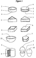
- FIG. 1 shows the strabismal figure of variety of the complex cell bodies.
- Complex cell body 1 is comprised of the light material 2 which is made from the urethane foam.
- Brim section 3 is made from a thin steel plate, is wrapped by the light material 2.
- any shape can be used. However, in this figure, only typical shapes are presented such as a cylindrical tube complex cell body 4, triangle complex cell body 5, rectangular complex cell body 6, pentagonal complex cell body 7.
- a can type complex cell body 9 which contains a light material 2, capsule type complex cell body 10 and half spherical/half bowl shape complex cell body 22.
- Figure 2 shows the example of the procedure to produce the hexagonal complex cell body 8.
- the light material which is already shaped hexagonally and is made from urethane foam, is prepared.
- the light material is then wrapped by the tin plate 11 along longitudinal direction of the tube and adhered. That is how to make the hexagonal tube complex cell body 40 which is comprised of the light material 2 and the brim made from thin layer of tin plate 11.
- this hexagonal tube 40 is cut to form slices by the lathe cutter to obtain many complex cell bodies 8.
- FIG 3 shows the procedure to make the plate type basic complex cell structure 34.
- the hexagonal complex cell bodies 8 are distributed and bonded by the adhesive on the plate type maintained spatial surface 14.
- the upper cover 15 is put in place. This happens is just before a coagulant, such as concrete, is poured.
- part of closer cover 15 is cut off so as to see the inside.
- Each inner portion of the a complex cell body is made from urethane foam 13, and the brim is made from a thin steel layer 11.
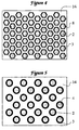
- Figure 4 shows the plane figure of an example of the distributed hexagonal complex cell structure 8 on the flat type maintained spatial surface 14.
- Figure 5 shows the plane figure of an example of the distributed cylindrical complex cell body 4 on the flat type maintained spatial surface 14.
- Figure 6 shows the strabismal figure of an example of the procedure to produce both of the hexagonal complex cell bodies for the flat type 42 and the hexagonal complex cell body for the curved type 43.
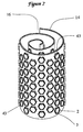
- Figure 7 shows the strabismal figure of a rolled type complex cell structure 16, just before the coagulant is poured.
- the necessary number of the hexagonal complex cell bodies for the curved type 43 are prepared. These complex cell bodies are distributed/bonded on the maintained spatial surface 14, it is then rolled to form a spiral shape.
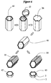
- Figure 8 shows the strabismal figure of an example of the procedure to produce the can type complex cell structure 9.
- a thin layered steel cylindrical can 31 is prepared, the foamed light material 2, which has already been formed and arranged to fit into the can, is also prepared.
- the material 2 is inserted into the can 31.
- the upper steel plate cap 33 and the bottom 32 is set in place, sealed, and bonded.
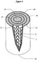
- Figure 9 shows the strabismal cross section figure of the annual ring type complex cell structure 20.
- This structure is made as follows.
- the prepared annual ring shaped complex cell structure 20 is inserted into the steel cylindrical tube 21. After insertion is complete, the coagulant is poured. The structure is cut by a cross section. The figure shows the inside so as to see more details on the inside the structure.
- the following is the procedure for producing such cylindrical tube, annual rings in the complex cell structure.
- three of the cylindrical plane maintaining bodies 29 are prepared, each with different diameters.
- the complex cell body for the curved type 43 is already prepared and are distributed on the cylindrical plane maintaining bodies 29 keeping with orderly gaps. They are then bonded onto the body using an adhesive.
- Figure 10 shows the strabismal figure of an example of the procedure to produce the plate type complex cell structure 30.
- the cylindrical complex cell bodies 4 are prepared. These bodies are then distributed/bonded on the flat type maintained spatial surface 14 in order.
- the second maintained spatial surface is attached to the cylindrical complex cell bodies which is produced in same manner as stated above. It is then overlapped on the first plane 14. Then the overlapped structure is put in the formwork 17, and the high liquidity concrete 18 is filled from the mouth 37. Also, notch 54 is installed, therefore the filling process is completed perfectly. After the coagulation is finished, the formwork 17 is removed. Finally, the plate type complex cell structure 30 is produced.
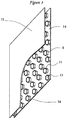
- Fig.11 shows an example of the basic structure which is comprised of the wave plate for the maintained spatial surface 19 and on which the triangle type complex cell body 5 is distributed/bonded.
- Figure 11 shows the basic structure (in this invention, the basic structure means the combination of maintained spatial surface and the complex cell bodies) on a plane view, the front view, the bottom view, the back view, and the left view and the right view.
- the triangle complex cell bodies 5 are distributed alternately on the wave plate on the maintained spatial surface 19, the space between each cell is empty space.
- the Figure 12 shows the strabismal figure of an example of the basic structure 12, which contains the triangle type complex cell bodies 5 distributed/bonded onto the surface.
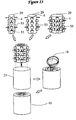
- Figure 13 shows the strabismal figure of an example of the procedure to produce the cylindrical tube type complex cell structure 45.
- several cylindrical tubes with varying diameters constitute the maintained spatial surface 29.
- the cylindrical complex cell bodies 4 are distributed/bonded, and prepared.
- the spacer 53 is installed to keep the distance between the tubes constant.
- the tubes are put inside the next larger tube and are then overlapped.
- the basic structures are inserted into the steel cylindrical, tubular vessel 21.
- the concrete 18 coagulant is poured from the upper inlet to fill the vessel. The concrete is then coagulated to obtain the cylindrical tube complex cell structure 45.
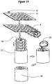
- Figure 14 shows the strabismal figure of an example of the procedure to produce the cylindrical tube complex cell structure 45 using a rolled version of the maintained spatial surface 46.
- the tin plate 11 is prepared, then the cylindrical complex cell bodies 4 are distributed/bonded on the maintained spatial surface. This flat basic structure is rolled by a rolling machine. Then, it is inserted into the steel, cylindrical tubular 21. Next, high liquidity concrete 18 is poured from the upper inlet. After tube 21 is filled with concrete 18, the concrete coagulates to obtain the cylindrical tube complex cell structure 45.
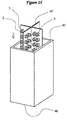
- Figure 15 shows an example of the basic structure of the square tube complex cell structure 48 using the perpendicular crossing maintained spatial surface 47.
- the cylindrical complex cell bodies 4 are distributed/bonded on the perpendicular crossing maintained spatial surface 47. It is then set inside the steel square tube vessel 49.
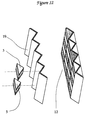
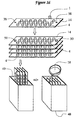
- Figure 16 shows the strabismal figure of an example of the procedure to produce the parallel square tube complex cell structure 48 using the flat plate maintained spatial surface 14.
- the thin, flat tin plate is prepared.
- the cylindrical complex cell bodies 4 are distributed/bonded on the tin plate.
- Four of the bonded tin plates are produced and are layered and fixed to each other by nuts and bolts 50 through the nut-bolt hole 38.
- this bolted plate is put into the steel, square tube vessel 49.
- liquid concrete 18 is poured into the vessel.
- the vessel 49 is filled with the concrete 18 as coagulant.
- the concrete 18 is coagulated to obtain the tube complex cell structure 48.
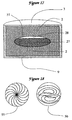
- Figure 17 shows the strabismal and cross section figure of an example of the complex cell body which contains liquid bag 26 inside of the cell.
- This is a kind of canned complex cell body 9, including the liquid bag 26 in the light material 2.
- the liquid bag is wrapped by a plastic thinner plastic film bag 51, the bag is filled with water 27 and air 28.
- the out frame of the light material 2 is made from a thin can like layer to compose the canned complex cell body 9.
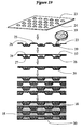
- Figure 18 shows the upper view of the cross section figure of two examples of the spiral and whirlpool shaped maintained spatial surface. In this figure, both one-pole whirlpool 55 and two-pole whirlpool type 56 plane maintaining bodies are shown.
- Figure 19 shows an example of the procedure of making the plate complex cell structure 30 which contains the distributed the complex cell bodies.
- the flat steel plate 23 is prepared.
- the mold is shown it's cross section has many trapezoid shaped cells and they are regularly distributed on the plate.
- the flat steel plate 23 is then pressed by the pressing machine using the mold to make indention of the trapezoid shape.
- the imprints 24 are produced.
- the pressed steel plate that has many of these indentions 24 is then produced.
- the thin plastic film liquid bags 51 whose sizes are smaller than that of the indentions size, is filled with water 27 and air 28, and are put in the indentions of the steel plate.
- the styrene foam resin 39 is placed in the indentions and at the same time the chemical adhesive 25 is spread on the convex areas of the flat steel plate 23. Then, it is concealed by the flat steel plate (it is not pressed, but is flat in shape) 52.
- the styrene foam 39 is then introduced. Three more plates are constructed using said procedure. The four plates are then stacked one upon the other. Liquid concrete 18 is poured into every empty space. It then coagulates. Finally the flat plate complex cell structure 30, which contains many liquid bags 26 inside, is produced.
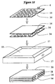
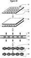
- Figure 20 shows an example of the procedure of making compressed complex cell structure 60 by distributing the urethane foam resin 13 in a grid-bike manner.
- the thin chemical film 57 on which the flat plate maintained spatial surface is already bonded to make the complex plate 58.
- the urethane foam resin 13 is distributed on the plate in a grid-like manner. It is then sandwiched by another plates. With the figure, in order to see more details, these plates are partially cut by a cross section. The plates are then compressed. The urethane foam is introduced.
- the complex plate 59 is formed. The plate is then cut into pieces to along each grid line 35 as it is shown in the figure. After the cutting has occurred, many pieces of the sandwiched complex cell bodies 60 are produced.
- this invention is composed as it is explained in detail above. There are many industrial advantages which are explained below.
- this invention's complex cell structure is a noble complex structure. It is a light, strong and tough structure. Also, from the production point of view, this structure is much easier to produce than the usual honeycomb structure. The use of formwork and complicated methods such as bending the material and binding it each others are not necessary processes any more. Thus, due to this invention, the industrial production of the complex cell structure, which contains numerous cells, becomes significantly easy. Therefore the cost, effort, labor, and time to produce it will be reduced considerably.
- the new complex cell structure becomes stronger, tougher and even lighter than any other conventional structure. Even if large scale loading is forced on the structure, many complex cell bodies fill the structure, so a sudden collapse will not happen as is case with ordinary hollow honeycomb structures. Therefore, a dynamically tougher structure is realized.
- any shape, side or density required by the structure can be attained.
- the strength, weight, and toughness of the pillar or beam can be freely designated. This means that the invention makes it possible to plan the dynamic character of a structure. It's strength, weight and toughness can be calculated in advance. All kinds of light but tough structures such as slabs, pillars and beams can be manufactured.
- the invention is used for constructing slabs, pillars and beams they become significantly lighter in weight. Carrying these objects becomes easier. Thus, the transportation cost is considerably reduced while moving these materials from one site to another.
- the invention is used for constructing slabs, pillars and beams they become significantly lighter weight and have increased toughness. When this is applied to the construction of skyscrapers or long bridges, these buildings or bridges will become much taller or longer. This technology provides for structures to be produced at greater heights and lengths than ever thought possible.
- the plates, beams and pillars using this invention's complex cell structure are produced at the factory.
- the invention structure can be used for the body or roof of automobile and car.
- the weight of the automobile is reduced, and that the strength becomes higher. Therefore, an energy saving automobile is produced, because the gas mileage has been increased. Consequently, the environmental pollution can be reduced.
- the side beams of an automobile can utilize this invention's structure.
- the structure absorbs loading energy when it is displaced. Because strength and the toughness increases in the car, if it crashes, the structure can sustain a heavier impact. Therefore, the automobile becomes safer for it's passengers.
- a ship can be built using this invention's structure.
- the structure's specific gravity becomes lighter than water.
- the structure can float.
- the invention can provide for ocean structures, such as floating airports and large floating structure such as ocean cities or platforms.
- the invention of complex cell structure can be used for any structure. Because the cell structure contains the foamed material, it can contain a higher ratio of gas. Therefore, the absorbing energy ratio becomes higher. This results in higher dampening or soundproof effects especially when used for making panels or plates. In the case of using liquid replacing instead of gas, an even higher dampening effect is expected.
- the heat transfer ratio becomes lower and heat insulation increases.
- the structure When the structure is built by many complex cell bodies, the inner hysteresis increases. Therefore, the structure can absorb noise and vibration. For example, an increased control of vibration can be expected when applied to automobile materials. A quieter automobile can be constructed.
- the invention structure has an essential higher structural dampening effect. Therefore a building using the invention structure increases resistance to shaking such as earthquake. When the liquid is used in the complex cell body, it's resistance increases even more. The structural dampening effect is produced by the liquid's absorption of more vibrations. This is more applicable to buildings requiring a higher resistance to earthquake. Also, this invention is applicable when constructing quieter buildings and houses, because of it's higher soundproof effect.
Landscapes
- Engineering & Computer Science (AREA)
- Architecture (AREA)
- Civil Engineering (AREA)
- Structural Engineering (AREA)
- Laminated Bodies (AREA)
- Bridges Or Land Bridges (AREA)
Applications Claiming Priority (1)
| Application Number | Priority Date | Filing Date | Title |
|---|---|---|---|
| PCT/JP1995/000108 WO1996023163A1 (en) | 1995-01-27 | 1995-01-27 | Compound cell structure and method for producing the same |
Publications (2)
| Publication Number | Publication Date |
|---|---|
| EP0807783A1 true EP0807783A1 (de) | 1997-11-19 |
| EP0807783A4 EP0807783A4 (de) | 2000-08-23 |
Family
ID=14125596
Family Applications (1)
| Application Number | Title | Priority Date | Filing Date |
|---|---|---|---|
| EP95906537A Withdrawn EP0807783A4 (de) | 1995-01-27 | 1995-01-27 | Zusammengesetzte zellstruktur und verfahren zu ihre herstellung |
Country Status (4)
| Country | Link |
|---|---|
| US (1) | US6017597A (de) |
| EP (1) | EP0807783A4 (de) |
| AU (1) | AU1467395A (de) |
| WO (1) | WO1996023163A1 (de) |
Cited By (1)
| Publication number | Priority date | Publication date | Assignee | Title |
|---|---|---|---|---|
| EP1398143A1 (de) * | 2002-09-10 | 2004-03-17 | Fritz Michael Streuber | Sandwich-Verbundkörper und Verfahren für die Herstellung eines Sandwich-Verbundkörpers |
Families Citing this family (25)
| Publication number | Priority date | Publication date | Assignee | Title |
|---|---|---|---|---|
| DE29805195U1 (de) * | 1998-03-21 | 1998-08-13 | Trumpf GmbH & Co., 71254 Ditzingen | Maschine zum Bearbeiten von plattenartigen Werkstücken, insbesondere von Blechen |
| USD465337S1 (en) | 2001-05-15 | 2002-11-12 | Polymer Group, Inc. | Apertured nonwoven fabric |
| JP4929435B2 (ja) * | 2001-07-31 | 2012-05-09 | 学校法人日本大学 | 圧力変換器 |
| USD549934S1 (en) * | 2006-05-18 | 2007-09-04 | Wolverine World Wide, Inc. | Footwear sole |
| US20090020216A1 (en) * | 2007-07-20 | 2009-01-22 | Gm Global Technology Operations, Inc. | Method Of Making Tailored Core Laminated Sheet Metal |
| US7919174B2 (en) * | 2007-07-20 | 2011-04-05 | GM Global Technology Operations LLC | Tailored core laminated sheet metal |
| US7743573B1 (en) * | 2007-09-17 | 2010-06-29 | Engineering Innovations, LLC | Roofing composition |
| US8714071B2 (en) * | 2010-05-21 | 2014-05-06 | Skydex Technologies, Inc. | Overpressure protection |
| US9091049B2 (en) | 2010-08-24 | 2015-07-28 | James Walker | Ventilated structural panels and method of construction with ventilated structural panels |
| US9604428B2 (en) | 2010-08-24 | 2017-03-28 | James Walker | Ventilated structural panels and method of construction with ventilated structural panels |
| US9050766B2 (en) | 2013-03-01 | 2015-06-09 | James Walker | Variations and methods of producing ventilated structural panels |
| US8615945B2 (en) * | 2010-08-24 | 2013-12-31 | James Walker | Ventilated structural panels and method of construction with ventilated structural panels |
| US8490355B2 (en) * | 2010-08-24 | 2013-07-23 | James Walker | Ventilated structural panels and method of construction with ventilated structural panels |
| US8534018B2 (en) | 2010-08-24 | 2013-09-17 | James Walker | Ventilated structural panels and method of construction with ventilated structural panels |
| US10822790B2 (en) * | 2010-08-24 | 2020-11-03 | Innovative Structural Building Products, Llc | Frameless construction using single and double plenum panels |
| USD674639S1 (en) * | 2011-01-31 | 2013-01-22 | Zigma Ground Solutions, Ltd. | Mat |
| CA2772874A1 (en) | 2011-04-21 | 2012-10-21 | Certainteed Corporation | System, method and apparatus for thermal energy management in a roof |
| CN103572867A (zh) * | 2012-08-07 | 2014-02-12 | 吴淑环 | 一种可滑移的装配式墙体 |
| AT513134B1 (de) * | 2012-11-15 | 2014-02-15 | Lb Engineering Gmbh | Verkleidungselement für ein Gebäude |
| US9499986B2 (en) * | 2013-09-24 | 2016-11-22 | Certainteed Corporation | System, method and apparatus for thermal energy management in a roof |
| US9963887B2 (en) | 2014-02-14 | 2018-05-08 | Norwood Architecture, Inc. | System and method for a vented and water control siding, vented and water control sheathing and vented and water control trim-board |
| EP3114289B1 (de) * | 2014-02-14 | 2023-12-06 | Norwood Architecture, Inc. | System für belüftungs- und feuchtigkeitsregelnde verkleidung |
| USD853099S1 (en) * | 2016-02-01 | 2019-07-09 | Nike, Inc. | Shoe |
| US11566430B2 (en) * | 2017-12-05 | 2023-01-31 | Louisiana-Pacific Corporation | Lap and panel siding with ventilation elements |
| CN110080092A (zh) * | 2019-04-08 | 2019-08-02 | 西南交通大学 | 防撞缓冲构件 |
Family Cites Families (19)
| Publication number | Priority date | Publication date | Assignee | Title |
|---|---|---|---|---|
| US3016315A (en) * | 1958-10-08 | 1962-01-09 | Carl D Hall Jr | Honeycomb structure and method |
| FR1262049A (fr) * | 1960-04-15 | 1961-05-26 | Panneaux Polyvalents Soc Et | Procédé de fabrication de panneaux isolants et panneaux obtenus selon le procédé |
| US3388509A (en) * | 1965-03-09 | 1968-06-18 | Raul L. Mora | Inflatable construction panels and method of making same |
| US3538668A (en) * | 1967-12-01 | 1970-11-10 | Howard A Anderson | Reinforced architectural shapes |
| JPS4816040U (de) * | 1971-07-06 | 1973-02-23 | ||
| JPS5111641B2 (de) * | 1971-10-13 | 1976-04-13 | ||
| US4068429A (en) * | 1975-04-21 | 1978-01-17 | Moore Alvin E | Wall and wall part |
| JPS57114774U (de) * | 1981-01-07 | 1982-07-16 | ||
| JPS5978417U (ja) * | 1982-11-19 | 1984-05-28 | 高木 賢次郎 | 負荷支持構造体 |
| US4495237A (en) * | 1983-06-10 | 1985-01-22 | Patterson Fred R | Pyramidal core structure |
| DE3412846A1 (de) * | 1984-04-05 | 1985-10-17 | Hoechst Ag, 6230 Frankfurt | Flaechenfoermiger sandwichformkoerper |
| DE3870043D1 (de) * | 1987-06-19 | 1992-05-21 | Giat Ind Sa | Leichte sandwichplatte verwendbar zur herstellung von waerme- und stossbestaendigen mehrschichtigen strukturen. |
| JPH0765379B2 (ja) * | 1988-01-22 | 1995-07-19 | 日本電気株式会社 | 自己補強型構造物材料 |
| US4875622A (en) * | 1988-06-23 | 1989-10-24 | James A. Waddell | Breakaway freestanding roadside structure and method for construction thereof |
| GB2275065B (en) * | 1991-09-24 | 1995-09-13 | Building Solutions Pty Ltd | Building panel and buildings using the panel |
| AU697396B2 (en) * | 1994-01-26 | 1998-10-08 | Peter Sing | Sandwich construction building materials |
| US5505030A (en) * | 1994-03-14 | 1996-04-09 | Hardcore Composites, Ltd. | Composite reinforced structures |
| US5615528A (en) * | 1994-11-14 | 1997-04-01 | Owens; Charles R. | Stress steering structure |
| JPH09151740A (ja) * | 1995-11-29 | 1997-06-10 | Ishikawajima Harima Heavy Ind Co Ltd | リショルムコンプレッサ用ダンパプーリ |
-
1995
- 1995-01-27 EP EP95906537A patent/EP0807783A4/de not_active Withdrawn
- 1995-01-27 WO PCT/JP1995/000108 patent/WO1996023163A1/ja not_active Ceased
- 1995-01-27 AU AU14673/95A patent/AU1467395A/en not_active Abandoned
- 1995-01-27 US US08/849,235 patent/US6017597A/en not_active Expired - Lifetime
Cited By (1)
| Publication number | Priority date | Publication date | Assignee | Title |
|---|---|---|---|---|
| EP1398143A1 (de) * | 2002-09-10 | 2004-03-17 | Fritz Michael Streuber | Sandwich-Verbundkörper und Verfahren für die Herstellung eines Sandwich-Verbundkörpers |
Also Published As
| Publication number | Publication date |
|---|---|
| WO1996023163A1 (en) | 1996-08-01 |
| US6017597A (en) | 2000-01-25 |
| EP0807783A4 (de) | 2000-08-23 |
| AU1467395A (en) | 1996-08-14 |
Similar Documents
| Publication | Publication Date | Title |
|---|---|---|
| US6017597A (en) | Complex cell structure and method for producing the same | |
| US3305991A (en) | Reinforced modular foam panels | |
| JP5663489B2 (ja) | 型枠の埋込システム | |
| US20190234065A1 (en) | Building Module with Pourable Foam and Cable | |
| US20050255289A1 (en) | Method for manufacture of cellular materials and structures for blast and impact mitigation and resulting structure | |
| WO1998002304A1 (en) | Concrete panel and method of production thereof | |
| CN112227187A (zh) | 一种分层梯度负泊松比蜂窝填充桥墩防撞装置 | |
| Zareef | Conceptual and structural design of buildings made of lightweight and infra-lightweight concrete | |
| US5678363A (en) | Sound barrier panel | |
| US3721058A (en) | Reinforced wall structure | |
| CN204475588U (zh) | 一种用钢质网状体与发泡水泥浇注的墙体 | |
| CN112195836A (zh) | 一种泡沫混凝土填充金字塔型三维点阵夹芯结构桥墩防撞装置 | |
| CN103328352B (zh) | 生产加强型定界元件的方法和所述元件 | |
| CN103314168A (zh) | 用于建筑物壁或者容器壁的保护系统 | |
| US5564241A (en) | Sound-barrier panel | |
| Miyamoto et al. | Design concept for reinforced concrete slab structures under soft impact loads | |
| JPH01268971A (ja) | 既設構造物の組積造壁体の移築工法 | |
| CN217580751U (zh) | 一种免支撑的全预制密肋空心楼板及空心楼盖 | |
| CN1062347C (zh) | 复合元件结构体及其制造方法 | |
| CN206090997U (zh) | 一种大跨度装配式空腔楼盖 | |
| CN204475651U (zh) | 一种机制钢质网状体与发泡水泥浇注的保温墙板 | |
| JPWO1996023163A1 (ja) | 複合セル構造体およびその製造方法 | |
| JPH0521522Y2 (de) | ||
| CN207032582U (zh) | 一种多重约束钢筋混凝土柱式墙结构及其结构体系 | |
| CN204753898U (zh) | 一种机制钢网与轻质无机物复合的自保温墙板 |
Legal Events
| Date | Code | Title | Description |
|---|---|---|---|
| PUAI | Public reference made under article 153(3) epc to a published international application that has entered the european phase |
Free format text: ORIGINAL CODE: 0009012 |
|
| 17P | Request for examination filed |
Effective date: 19970827 |
|
| AK | Designated contracting states |
Kind code of ref document: A1 Designated state(s): DE FR GB |
|
| A4 | Supplementary search report drawn up and despatched |
Effective date: 20000706 |
|
| AK | Designated contracting states |
Kind code of ref document: A4 Designated state(s): DE FR GB |
|
| STAA | Information on the status of an ep patent application or granted ep patent |
Free format text: STATUS: THE APPLICATION IS DEEMED TO BE WITHDRAWN |
|
| 18D | Application deemed to be withdrawn |
Effective date: 20000801 |