EP0807757A1 - Fuel injection valve for internal combustion engines - Google Patents
Fuel injection valve for internal combustion engines Download PDFInfo
- Publication number
- EP0807757A1 EP0807757A1 EP97112502A EP97112502A EP0807757A1 EP 0807757 A1 EP0807757 A1 EP 0807757A1 EP 97112502 A EP97112502 A EP 97112502A EP 97112502 A EP97112502 A EP 97112502A EP 0807757 A1 EP0807757 A1 EP 0807757A1
- Authority
- EP
- European Patent Office
- Prior art keywords
- injection valve
- fuel
- control
- pressure
- fuel injection
- Prior art date
- Legal status (The legal status is an assumption and is not a legal conclusion. Google has not performed a legal analysis and makes no representation as to the accuracy of the status listed.)
- Withdrawn
Links
Images
Classifications
-
- F—MECHANICAL ENGINEERING; LIGHTING; HEATING; WEAPONS; BLASTING
- F02—COMBUSTION ENGINES; HOT-GAS OR COMBUSTION-PRODUCT ENGINE PLANTS
- F02M—SUPPLYING COMBUSTION ENGINES IN GENERAL WITH COMBUSTIBLE MIXTURES OR CONSTITUENTS THEREOF
- F02M47/00—Fuel-injection apparatus operated cyclically with fuel-injection valves actuated by fluid pressure
- F02M47/02—Fuel-injection apparatus operated cyclically with fuel-injection valves actuated by fluid pressure of accumulator-injector type, i.e. having fuel pressure of accumulator tending to open, and fuel pressure in other chamber tending to close, injection valves and having means for periodically releasing that closing pressure
- F02M47/027—Electrically actuated valves draining the chamber to release the closing pressure
-
- F—MECHANICAL ENGINEERING; LIGHTING; HEATING; WEAPONS; BLASTING
- F02—COMBUSTION ENGINES; HOT-GAS OR COMBUSTION-PRODUCT ENGINE PLANTS
- F02M—SUPPLYING COMBUSTION ENGINES IN GENERAL WITH COMBUSTIBLE MIXTURES OR CONSTITUENTS THEREOF
- F02M45/00—Fuel-injection apparatus characterised by having a cyclic delivery of specific time/pressure or time/quantity relationship
-
- F—MECHANICAL ENGINEERING; LIGHTING; HEATING; WEAPONS; BLASTING
- F02—COMBUSTION ENGINES; HOT-GAS OR COMBUSTION-PRODUCT ENGINE PLANTS
- F02M—SUPPLYING COMBUSTION ENGINES IN GENERAL WITH COMBUSTIBLE MIXTURES OR CONSTITUENTS THEREOF
- F02M61/00—Fuel-injectors not provided for in groups F02M39/00 - F02M57/00 or F02M67/00
- F02M61/16—Details not provided for in, or of interest apart from, the apparatus of groups F02M61/02 - F02M61/14
- F02M61/20—Closing valves mechanically, e.g. arrangements of springs or weights or permanent magnets; Damping of valve lift
- F02M61/205—Means specially adapted for varying the spring tension or assisting the spring force to close the injection-valve, e.g. with damping of valve lift
-
- F—MECHANICAL ENGINEERING; LIGHTING; HEATING; WEAPONS; BLASTING
- F02—COMBUSTION ENGINES; HOT-GAS OR COMBUSTION-PRODUCT ENGINE PLANTS
- F02M—SUPPLYING COMBUSTION ENGINES IN GENERAL WITH COMBUSTIBLE MIXTURES OR CONSTITUENTS THEREOF
- F02M2200/00—Details of fuel-injection apparatus, not otherwise provided for
- F02M2200/30—Fuel-injection apparatus having mechanical parts, the movement of which is damped
- F02M2200/304—Fuel-injection apparatus having mechanical parts, the movement of which is damped using hydraulic means
-
- F—MECHANICAL ENGINEERING; LIGHTING; HEATING; WEAPONS; BLASTING
- F02—COMBUSTION ENGINES; HOT-GAS OR COMBUSTION-PRODUCT ENGINE PLANTS
- F02M—SUPPLYING COMBUSTION ENGINES IN GENERAL WITH COMBUSTIBLE MIXTURES OR CONSTITUENTS THEREOF
- F02M2547/00—Special features for fuel-injection valves actuated by fluid pressure
- F02M2547/001—Control chambers formed by movable sleeves
-
- F—MECHANICAL ENGINEERING; LIGHTING; HEATING; WEAPONS; BLASTING
- F02—COMBUSTION ENGINES; HOT-GAS OR COMBUSTION-PRODUCT ENGINE PLANTS
- F02M—SUPPLYING COMBUSTION ENGINES IN GENERAL WITH COMBUSTIBLE MIXTURES OR CONSTITUENTS THEREOF
- F02M63/00—Other fuel-injection apparatus having pertinent characteristics not provided for in groups F02M39/00 - F02M57/00 or F02M67/00; Details, component parts, or accessories of fuel-injection apparatus, not provided for in, or of interest apart from, the apparatus of groups F02M39/00 - F02M61/00 or F02M67/00; Combination of fuel pump with other devices, e.g. lubricating oil pump
- F02M63/0012—Valves
- F02M63/0031—Valves characterized by the type of valves, e.g. special valve member details, valve seat details, valve housing details
- F02M63/0054—Check valves
-
- Y—GENERAL TAGGING OF NEW TECHNOLOGICAL DEVELOPMENTS; GENERAL TAGGING OF CROSS-SECTIONAL TECHNOLOGIES SPANNING OVER SEVERAL SECTIONS OF THE IPC; TECHNICAL SUBJECTS COVERED BY FORMER USPC CROSS-REFERENCE ART COLLECTIONS [XRACs] AND DIGESTS
- Y10—TECHNICAL SUBJECTS COVERED BY FORMER USPC
- Y10T—TECHNICAL SUBJECTS COVERED BY FORMER US CLASSIFICATION
- Y10T137/00—Fluid handling
- Y10T137/8593—Systems
- Y10T137/86389—Programmer or timer
- Y10T137/86405—Repeating cycle
Definitions
- the invention relates to a fuel injection valve for intermittent fuel injection into the combustion chamber of an internal combustion engine.
- the invention solves the problem of creating a fuel injector which is extremely simple in terms of production and assembly technology.
- the fuel injection valve 1 shows a fuel injection valve 1 in a position between two injection processes.
- the fuel injection valve 1 is connected via a high-pressure fuel connection 10 and via a fuel return connection 12 to a high-pressure delivery device for the fuel and via electrical connections 14 to an electronic control.
- the high-pressure conveyor and the electronic control are not shown in the drawing.
- the housing of the fuel injector 1 is designated 15. At the lower end is on the housing 15 as Retaining nut trained retaining part 16, a corresponding retaining nut 17 screwed on at the upper end.
- a nozzle body 18 is inserted in the holding part 16, the nozzle tip 19 of which protrudes from the holding part 16.
- the nozzle tip 19 is provided with a nozzle needle seat 20 and has a plurality of injection openings 21 in this area.
- an axially adjustable nozzle needle 24 forming an injection valve member is slidably guided in a needle guide bore 23.
- the injection openings 21 of the nozzle tip 19 can be closed by a lower end 25 of the nozzle needle 24.
- the housing 15 is provided with a central guide bore 29 in which a control device 3 for controlling the adjustment movement of the injection valve member or the nozzle needle 24 is arranged.
- the control device 3 is described in detail below with reference to FIG. 2.
- the fuel is conveyed by the high-pressure delivery device via the high-pressure fuel connection 10 and a first short fuel supply bore 31 into two high-pressure supply lines 32, 33 arranged in the housing 15 parallel to the guide bore 29.
- the upper high-pressure supply line 33 leads to the control device 3.
- the lower high-pressure supply line 32 is connected via a connecting bore 35 arranged obliquely in an intermediate plate 36 to a nozzle body bore 26 which opens into an annular space 27 in the nozzle body 18. From the annular space 27, the fuel reaches the nozzle needle seat 20 or the injection openings 21 via passages (not shown in detail).
- the intermediate plate 36 is positioned opposite the housing 15 via a pin 37 (it could also be two pins 37) and is arranged sealingly between the housing 15 and the nozzle body 18.
- a pin 37 it could also be two pins 37
- One in a central bore 38 of the Intermediate plate 36 protruding upper part 39 of the nozzle needle 24 is operatively connected to an intermediate needle element 40, which on the other hand is connected to a control piston 50 of the control device 3 via a connecting rod 44.
- a nozzle needle spring 47 surrounding the connecting rod 44 is arranged pretensioned.
- the control device 3 has a control body 52 which is inserted into the guide bore 29 in a stationary manner.
- the control piston 50 is provided with an upper piston part 51 of reduced diameter.
- the upper piston part 51 projects into a sleeve 64 which is axially displaceable and closely sliding in the guide bore 29. Close sliding fits are also provided between the piston part 51 and the inner diameter of the sleeve 64.
- a spring 63 is arranged between a lower end face 65 of the sleeve 64 and a piston shoulder surface 53.
- the sleeve 64 is supported with a narrow annular sealing surface 66 on a lower end face 55 of the control body 52, which on the other hand is axially fixed in the guide bore 29 by a lock nut 54 screwed to the housing 15.
- control body 52 In the lower region of the control body 52 there is an annular space 69 in the housing 15, which is connected to the upper high-pressure supply line 33 via a transverse bore 68.
- the control body 52 has a circumferential annular groove 67 corresponding to the annular space 69.
- the control body 52 is provided with a connection bore 60 opening into a first control space 70, which is connected via an inlet throttle bore 58 to the circumferential annular groove 67 or to the annular space 69 and thus also to the high-pressure supply line 33.
- the connection bore 60 narrows into an outlet opening 59.
- the first control chamber 70 is delimited radially by the inner surface of the sleeve 64, axially by the lower end surface 55 of the control body 52 and an upper end surface 56 of the piston part 51.
- the control body 52 is installed in the guide bore 29 of the housing 15 in such a way that no significant leakage can take place. This will e.g. achieved with a press fit or a narrow sliding fit, but could also be realized by other fuel-tight connections, for example using suitable sealing rings.
- the control device 3 also has an electromagnetically actuated pilot valve 80, of which only one armature 82, which is firmly connected to a pilot valve stem 81, can be seen in FIG. In the position shown in FIG. 2, the outlet throttle bore 59 is held in the closed position via a flat valve seat 85. As can be seen from FIG. 1, in the de-energized state of an electromagnet 86, the pilot valve stem 81 is pressed downward into the position closing the valve flat seat 85 by the force of a compression spring 87. This force can be adjusted in size by means of an adjusting screw 88. To actuate the pilot valve 80 or to raise the pilot valve stem 81 from the flat valve seat 85, an excitation coil 83 of the electromagnet 86 assigned to the armature 82 receives control pulses from the electronic control via the electrical connections 14.
- the fuel emerging from the outlet opening 59 when the pilot valve stem 81 is raised is collected in a discharge space 89 and fed via a discharge bore 90 to the fuel return connection 12, which is installed together with the electromagnet 86 in the holding nut 17.
- the fuel accumulated by leaks in a space 91 below the control piston 50 also flows into the discharge space 89 via a relief bore 92. Part of the fuel is thus returned to the high-pressure delivery device practically without pressure.
- the space 91, the relief bore 92, the drain space 89 and the drain bore 90 form a so-called low-pressure part of the fuel injection valve 1.
- the armature 82 is attracted against the force of the spring 87, whereby the pilot valve 80 is opened.
- the outlet opening 59 of the control body 52 is thus opened.
- the pressure in the first control chamber 70 drops.
- the nozzle needle 24 is raised from the nozzle needle seat 20 by the fuel pressure prevailing in the annular space 27 and acting on the shoulder 28.
- the injection openings 21 are opened and the fuel is injected into the combustion chamber of the internal combustion engine in a manner known per se.
- the control piston 50 When the nozzle needle 24 is raised, the control piston 50 is also moved upward via the intermediate needle element 40 and the connecting rod 44.
- the volume of the second control chamber 74 becomes smaller, the pressure in the control chamber 74 increases under this pumping action.
- the sleeve 64 is pressed even more strongly into the sealing position with respect to the control body 52.
- the pressure in the second control chamber 74 which counteracts the opening movement of the injection valve member or the nozzle needle 24, is defined in a desired, controlled manner via the connecting bore 75 and the throttle 77, which lead to the high-pressure supply line 33. A desired, controlled opening of the injection valve is thereby achieved.
- the end of the injection process should take place as quickly as possible.
- the pilot valve 80 is brought into its closed position via the electromagnet 86. Since the outlet opening 59 is now closed again, the pressure in the first control chamber 70 increases, and the control piston 50 is moved downward by the force acting on the upper end face 56 of the piston part 51. The volume of the second control chamber 74 is increased, the fuel pressure in the second control chamber 74 drops. The sleeve 64 initially remains pressed onto the control body 52. When the fuel pressure in the second control chamber 74 drops, the sleeve 64 follows the piston movement; it should be mentioned that the spring 63 is biased relatively weakly, so that the pressure effect of the spring 63 is negligible compared to the fuel pressure forces.
- the spring 63 presses the sleeve 64 with the sealing surface 66 into the position radially delimiting the first control chamber 70.
Landscapes
- Engineering & Computer Science (AREA)
- Chemical & Material Sciences (AREA)
- Combustion & Propulsion (AREA)
- Mechanical Engineering (AREA)
- General Engineering & Computer Science (AREA)
- Physics & Mathematics (AREA)
- Fluid Mechanics (AREA)
- Fuel-Injection Apparatus (AREA)
Abstract
Description
Die Erfindung betrifft ein Brennstoffeispritzventil zur intermittierenden Brennstoffeinspritzung in den Brennraum einer Verbrennungskraftmaschine.The invention relates to a fuel injection valve for intermittent fuel injection into the combustion chamber of an internal combustion engine.
Die Erfindung, wie sie in den Ansprüchen gekennzeichnet ist, löst die Aufgabe, ein Brennstoffeinspritzventil zu schaffen, das herstellungs- und montagetechnisch äusserst einfach ist.The invention, as characterized in the claims, solves the problem of creating a fuel injector which is extremely simple in terms of production and assembly technology.
Die Erfindung wird im folgenden anhand des in der Zeichnung gezeigten Ausführungsbeispieles näher beschrieben.The invention is described below with reference to the embodiment shown in the drawing.
Es zeigt:
- Fig.1
- ein Brennstoffeinspritzventil im Längsschnitt; und
- Fig.2
- im vergrössertem Massstab und im Längsschnitt die Steuervorrichtung des Brennstoffeinspritzventils gemäss Fig. 1.
- Fig. 1
- a fuel injector in longitudinal section; and
- Fig. 2
- on an enlarged scale and in longitudinal section, the control device of the fuel injector according to FIG. 1.
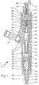
In Fig.1 ist ein Brennstoffeinspritzventil 1 in einer Stellung zwischen zwei Einspritzvorgängen dargestellt. Das Brennstoffeinspritzventil 1 ist über einen Brennstoffhochdruckanschluss 10 und über einen Brennstoffrücklaufanschluss 12 mit einer Hochdruck-Fördereinrichtung für den Brennstoff und über elektrische Anschlüsse 14 mit einer elektronischen Steuerung verbunden. Die Hochdruck-Fördereinrichtung und die elektronische Steuerung sind in der Zeichnung nicht dargestellt.1 shows a
Das Gehäuse des Brennstoffeinspritzventils 1 ist mit 15 bezeichnet. Am unteren Ende ist auf das Gehäuse 15 ein als Überwurfmutter ausgebildeter Halteteil 16, am oberen Ende eine entsprechende Haltemutter 17 aufgeschraubt.The housing of the
Im Halteteil 16 ist ein Düsenkörper 18 eingesetzt, dessen Düsenspitze 19 aus dem Halteteil 16 hinausragt. Die Düsenspitze 19 ist mit einem Düsennadelsitz 20 versehen und weist in diesem Bereich mehrere Einspritzöffnungen 21 auf. Im Düsenkörper 18 ist eine ein Einspritzventilglied bildende, axial verstellbare Düsennadel 24 in einer Nadelführungsbohrung 23 gleitend geführt. Die Einspritzöffnungen 21 der Düsenspitze 19 sind durch ein unteres Ende 25 der Düsennadel 24 abschliessbar.A
Das Gehäuse 15 ist mit einer zentralen Führungsbohrung 29 versehen, in welcher eine Steuervorrichtung 3 zur Steuerung der Verstellbewegung des Einspritzventilgliedes bzw.der Düsennadel 24 angeordnet ist. Die Steuervorrichtung 3 wird weiter unten anhand der Fig.2 ausführlich beschrieben.The
Der Brennstoff wird durch die Hochdruck-Fördereinrichtung über den Brennstoffhochdruckanschluss 10 und eine erste kurze Brennstoffzufuhrbohrung 31 in zwei im Gehäuse 15 parallel zur Führungsbohrung 29 angeordneten Hochdruckzufuhrleitungen 32,33 gefördert. Die obere Hochdruckzufuhrleitung 33 führt zur Steuervorrichtung 3. Die untere Hochdruckzufuhrleitung 32 ist über eine schräg in einer Zwischenplatte 36 angeordnete Verbindungsbohrung 35 an eine Düsenkörperbohrung 26 angeschlossen, die in einen Ringraum 27 im Düsenkörper 18 mündet. Vom Ringraum 27 gelangt der Brennstoff über nicht näher dargestellte Durchgänge zum Düsennadelsitz 20 bzw. zu den Einspritzöffnungen 21. Im Bereich des Ringraumes 27 ist die Düsennadel 24 mit einem Absatz 28 versehen.The fuel is conveyed by the high-pressure delivery device via the high-
Die Zwischenplatte 36 ist gegenüber dem Gehäuse 15 über einen Stift 37 (es könnten auch zwei Stifte 37 sein) positioniert und dichtend zwischen dem Gehäuse 15 und dem Düsenkörper 18 angeordnet. Ein in eine zentrale Bohrung 38 der Zwischenplatte 36 hineinragender oberer Teil 39 der Düsennadel 24 ist mit einem Nadel-Zwischenelement 40 wirkverbunden, das anderseits über eine Verbindungsstange 44 mit einem Steuerkolben 50 der Steuervorrichtung 3 verbunden ist. Zwischen einer sich an einem Absatz 45 des Gehäuses 15 abstützenden Federspannscheibe 46 und dem Nadel-Zwischenelement 40 ist eine die Verbindungsstange 44 umgebende Düsennadelfeder 47 vorgespannt angeordnet.The
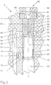
Die Steuervorrichtung 3 weist einen in die Führungsbohrung 29 ortsfest eingesetzten Steuerkörper 52 auf. Der Steuerkolben 50 ist mit einem oberen, im Durchmesser abgesetzten Kolbenteil 51 versehen. Wie besonders aus Fig.2 ersichtlich ist, ragt das obere Kolbenteil 51 in eine in der Führungsbohrung 29 axial verschiebbar und eng gleitend angeordnete Hülse 64 hinein. Auch zwischen dem Kolbenteil 51 und dem Innendurchmesser der Hülse 64 sind enge Gleitpassungen vorgesehen. Zwischen einer unteren Stirnfläche 65 der Hülse 64 und einer Kolbenabsatzfläche 53 ist eine Feder 63 angeordnet. Die Hülse 64 stützt sich mit einer schmalen ringförmigen Dichtfläche 66 an einer unteren Stirnfläche 55 des Steuerkörpers 52 ab, der anderseits durch eine mit dem Gehäuse 15 verschraubte Sicherungsmutter 54 in der Führungsbohrung 29 axial fixiert ist.The
Im unteren Bereich des Steuerkörpers 52 befindet sich im Gehäuse 15 ein Ringraum 69, der über eine Querbohrung 68 an die obere Hochdruckzufuhrleitung 33 angeschlossen ist. Der Steuerkörper 52 weist eine dem Ringraum 69 entsprechende Umfangsringnut 67 auf. Ferner ist der Steuerkörper 52 mit einer in einen ersten Steuerraum 70 mündenden Verbindungsbohrung 60 versehen, die über eine Einlassdrosselbohrung 58 mit der Umfangsringnut 67 bzw. mit dem Ringraum 69 und somit auch mit der Hochdruckzufuhrleitung 33 verbunden ist. Oben verengt sich die Verbindungsbohrung 60 in eine Auslassöffnung 59.In the lower region of the
Der erste Steuerraum 70 ist radial durch die Innenfläche der Hülse 64 , axial durch die untere Stirnfläche 55 des Steuerkörpers 52 und eine obere Stirnfläche 56 des Kolbenteils 51 begrenzt.The
Zwischen dem Kolbenteil 51 und der Führungsbohrung 29 befindet sich unterhalb der Hülse 64 ein ringförmiger, zweiter Steuerraum 74, in dem auch die Feder 63 angeordnet ist, und der über eine Verbindungsbohrung 75 an die Hochdruckzufuhrleitung 33 angeschlossen ist. In die Verbindungsbohrung 75 ist eine Blende 76 mit einer Drossel 77 eingesetzt.Between the
Der Steuerkörper 52 ist in die Führungsbohrung 29 des Gehäuses 15 derart eingebaut, dass keine nennenswerte Leckage stattfinden kann. Dies wird z.B. mit einem Pressitz oder einem engen Schiebesitz erreicht, könnte allerdings auch durch andere brennstoffdichte Verbindungen, beispielsweise unter Verwendung von geeigneten Dichtungsringen realisiert werden.The
Die Steuervorrichtung 3 weist ferner ein elektromagnetisch betätigbares Pilotventil 80 auf, von dem in Fig.2 lediglich ein mit einem Pilotventilschaft 81 fest verbundener Anker 82 ersichtlich ist. In der in Fig.2 dargestellten Stellung wird die Auslassdrosselbohrung 59 über einen Ventil-Flachsitz 85 in der geschlossener Stellung gehalten. Wie aus Fig.1 zu sehen ist, wird dabei im stromlosen Zustand eines Elektromagnets 86 der Pilotventilschaft 81 durch die Kraft einer Druckfeder 87 nach unten in die den Ventil-Flachsitz 85 schliessende Stellung gedrückt. Diese Kraft ist mittels einer Einstellschraube 88 in ihrer Grösse einstellbar. Zur Betätigung des Pilotventils 80 bzw. zur Anhebung des Pilotventilschaftes 81 vom Ventil-Flachsitz 85 erhält eine dem Anker 82 zugeordnete Erregerspule 83 des Elektromagnets 86 über die elektrischen Anschlüsse 14 Steuerimpulse von der elektronischen Steuerung.The
Der beim Anheben des Pilotventilschaftes 81 aus der Auslassöffnung 59 austretende Brennstoff wird gemäss Fig.1 in einem Abflussraum 89 gesammelt und über eine Abflussbohrung 90 dem Brennstoffrücklaufanschluss 12 zugeführt, der zusammen mit dem Elektromagneten 86 in der Haltemutter 17 eingebaut ist. In den Abflussraum 89 fliesst auch über eine Entlastungsbohrung 92 der durch Leckagen in einem Raum 91 unterhalb des Steuerkolbens 50 angesammelte Brennstoff. Somit wird ein Teil des Brennstoffes praktisch drucklos der Hochdruck-Fördereinrichtung zurückgeführt. Der Raum 91, die Entlastungsbohrung 92, der Abflussraum 89 und die Abflussbohrung 90 bilden einen sogenannten Niederdruckteil des Brennstoffeinspritzventils 1.According to FIG. 1, the fuel emerging from the outlet opening 59 when the
Aus dem beschriebenen Aufbau ergibt sich folgende Wirkungsweise des Brennstoffeinspritzventils 1:The following mode of operation of
Vor dem Einspritzvorgang herrscht im Hochdruckteil des Brennstoffeinspritzventils 1, d.h. in der Brennstoffzufuhrbohrung 31, in beiden Hochdruckzufuhrleitungen 32,33, in den Ringräumen 27,69 und in beiden Steuerräumen 70,74 der gleiche Hochdruck bzw. Einspritzdruck, der bis über 1000 bar betragen kann.Before the injection process, the high-pressure part of the
Sobald über die elektronische Steuerung ein Impuls von gewählter Dauer dem Elektromagnet 86 erteilt wird, wird der Anker 82 entgegen der Kraft der Feder 87 angezogen, wodurch das Pilotventil 80 geöffnet wird. Somit wird die Auslassöffnung 59 des Steuerkörpers 52 geöffnet. Der Druck im ersten Steuerraum 70 sinkt. Die Düsennadel 24 wird durch den im Ringraum 27 herrschenden und auf den Absatz 28 wirkenden Brennstoffdruck vom Düsennadelsitz 20 angehoben. Die Einspritzöffnungen 21 werden freigegeben, und der Brennstoff wird in an sich bekannter Weise in den Brennraum der Verbrennungskraftmaschine eingespritzt.As soon as a pulse of selected duration is given to the
Beim Anheben der Düsennadel 24 wird auch über das Nadel-Zwischenelement 40 und die Verbindungsstange 44 der Steuerkolben 50 nach oben bewegt. Das Volumen des zweiten Steuerraumes 74 wird kleiner, der Druck im Steuerraum 74 steigt unter dieser Pumpwirkung. Die Hülse 64 wird noch stärker in die dichtende Stellung gegenüber dem Steuerkörper 52 gedrückt. Über die Verbindungsbohrung 75 und die Drossel 77, die zur Hochdruckzufuhrleitung 33 führen, wird der der Öffnungsbewegung des Einspritzventilgliedes bzw. der Düsennadel 24 entgegenwirkende Druck im zweiten Steuerraum 74 in gewünschter, kontrollierter Weise definiert. Dadurch wird ein angestrebtes, kontrolliertes Öffnen des Einspritzventils erreicht.When the
Die Beendigung des Einspritzvorgangs soll bekanntlich möglichst rasch erfolgen. Wiederum elektronisch gesteuert wird über den Elektromagnet 86 das Pilotventil 80 in seine Schliessstellung gebracht. Da nun die Auslassöffnung 59 wieder geschlossen ist, steigt im ersten Steuerraum 70 der Druck an, und der Steuerkolben 50 wird durch die auf die obere Stirnfläche 56 des Kolbenteils 51 einwirkende Kraft nach unten bewegt. Das Volumen des zweiten Steuerraumes 74 wird vergrössert, der Brennstoffdruck im zweiten Steuerraum 74 fällt. Die Hülse 64 bleibt anfänglich an den Steuerkörper 52 angedrückt. Beim bestimmten Absinken des Brennstoffdruckes im zweiten Steuerraum 74 folgt die Hülse 64 der Kolbenbewegung; dazu ist zu erwähnen, dass die Feder 63 relativ schwach vorgespannt ist, so dass die Druckwirkung der Feder 63 vernachlässigbar ist gegenüber den Brennstoffdruckkräften. Sobald sich die Hülse 64 mit der Dichtfläche 66 vom Steuerkörper 52 abhebt, gelangt schlagartig über diese neue Verbindung Brennstoff vom Ringraum 69 bzw. aus der Hochdruckzufuhrleitung 33 in den ersten Steuerraum 70. Der Steuerkolben 50 sowie auch die Hülse 64 werden nach unten beschleunigt; über die Verbindungsstange 44 und das Nadel-Zwischenelement 40 wird die Düsennadel 24 in die die Einspritzöffnungen 21 schliessende Stellung gedrückt. In dieser Weise wird beim Brennstoffeinspritzventil 1 ein rascher Schliessvorgang realisiert.As is known, the end of the injection process should take place as quickly as possible. Again, electronically controlled, the
Sobald der Druck im zweiten Steuerraum 74 über die Drossel 77 und die Verbindungsbohrung 75 wieder dem Systembrennstoffhochdruck angeglichen wird, drückt die Feder 63 die Hülse 64 mit der Dichtfläche 66 in die den ersten Steuerraum 70 radial begrenzende Stellung.As soon as the pressure in the
Claims (6)
Applications Claiming Priority (3)
| Application Number | Priority Date | Filing Date | Title |
|---|---|---|---|
| CH178294 | 1994-06-06 | ||
| CH1782/94 | 1994-06-06 | ||
| EP95107718A EP0686763B1 (en) | 1994-06-06 | 1995-05-20 | Fuel injection valve for internal combustion engines |
Related Parent Applications (2)
| Application Number | Title | Priority Date | Filing Date |
|---|---|---|---|
| EP95107718.9 Division | 1995-05-20 | ||
| EP95107718A Division EP0686763B1 (en) | 1994-06-06 | 1995-05-20 | Fuel injection valve for internal combustion engines |
Publications (1)
| Publication Number | Publication Date |
|---|---|
| EP0807757A1 true EP0807757A1 (en) | 1997-11-19 |
Family
ID=4218485
Family Applications (2)
| Application Number | Title | Priority Date | Filing Date |
|---|---|---|---|
| EP95107718A Expired - Lifetime EP0686763B1 (en) | 1994-06-06 | 1995-05-20 | Fuel injection valve for internal combustion engines |
| EP97112502A Withdrawn EP0807757A1 (en) | 1994-06-06 | 1995-05-20 | Fuel injection valve for internal combustion engines |
Family Applications Before (1)
| Application Number | Title | Priority Date | Filing Date |
|---|---|---|---|
| EP95107718A Expired - Lifetime EP0686763B1 (en) | 1994-06-06 | 1995-05-20 | Fuel injection valve for internal combustion engines |
Country Status (5)
| Country | Link |
|---|---|
| US (2) | US5685483A (en) |
| EP (2) | EP0686763B1 (en) |
| JP (1) | JPH07332193A (en) |
| AT (1) | ATE184078T1 (en) |
| DE (1) | DE59506715D1 (en) |
Cited By (1)
| Publication number | Priority date | Publication date | Assignee | Title |
|---|---|---|---|---|
| WO2002073023A1 (en) * | 2001-03-12 | 2002-09-19 | Robert Bosch Gmbh | Injection nozzle |
Families Citing this family (49)
| Publication number | Priority date | Publication date | Assignee | Title |
|---|---|---|---|---|
| FI101738B1 (en) * | 1996-01-30 | 1998-08-14 | Waertsilae Nsd Oy Ab | An injection valve |
| GB9606803D0 (en) * | 1996-03-30 | 1996-06-05 | Lucas Ind Plc | Injection nozzle |
| DE19618468C1 (en) * | 1996-05-08 | 1997-04-30 | Siemens Ag | Hydraulically actuated fuel injection valve for combustion engine |
| FR2752268B1 (en) * | 1996-08-07 | 1998-09-18 | Froment Jean Louis | DEVICE FOR IMPROVING THE FUEL INJECTION DYNAMICS FOR DIESEL ENGINES EQUIPPED WITH PULSED INJECTION PUMPS |
| GB9624513D0 (en) * | 1996-11-26 | 1997-01-15 | Lucas Ind Plc | Injector |
| GB9700491D0 (en) * | 1997-01-11 | 1997-02-26 | Lucas Ind Plc | Injector |
| US6237570B1 (en) * | 1997-10-09 | 2001-05-29 | Denso Corporation | Accumulator fuel injection apparatus |
| DE19744518A1 (en) * | 1997-10-09 | 1999-04-15 | Bosch Gmbh Robert | Fuel injection valve for internal combustion engine |
| DE19826791A1 (en) * | 1998-06-16 | 1999-12-23 | Bosch Gmbh Robert | Valve control unit for a fuel injector |
| DE59903599D1 (en) * | 1998-11-10 | 2003-01-09 | Ganser Hydromag Ag Zuerich | FUEL INJECTION VALVE FOR INTERNAL COMBUSTION ENGINES |
| DE19936668A1 (en) | 1999-08-04 | 2001-02-22 | Bosch Gmbh Robert | Common rail injector |
| EP1081372B1 (en) * | 1999-08-31 | 2004-10-13 | Denso Corporation | Fuel injection device |
| DE19949526A1 (en) * | 1999-10-14 | 2001-04-19 | Bosch Gmbh Robert | Injector for a common rail fuel injection system for internal combustion engines with partial force compensation of the nozzle needle |
| US6293254B1 (en) * | 2000-01-07 | 2001-09-25 | Cummins Engine Company, Inc. | Fuel injector with floating sleeve control chamber |
| EP1118765A3 (en) * | 2000-01-19 | 2003-11-19 | CRT Common Rail Technologies AG | Fuel injector for internal combustion engines |
| US6283441B1 (en) | 2000-02-10 | 2001-09-04 | Caterpillar Inc. | Pilot actuator and spool valve assembly |
| DE10006915B4 (en) * | 2000-02-16 | 2004-02-05 | Siemens Ag | Orifice arrangement |
| DE10015740C2 (en) * | 2000-03-29 | 2003-12-18 | Siemens Ag | Injection valve for injecting fuel into an internal combustion engine |
| JP3551898B2 (en) * | 2000-06-15 | 2004-08-11 | トヨタ自動車株式会社 | Fuel injection valve |
| US6412473B1 (en) | 2000-06-29 | 2002-07-02 | Caterpillar Inc. | Rate shaped fluid driven piston assembly and fuel injector using same |
| DE10031576C2 (en) * | 2000-06-29 | 2002-07-11 | Bosch Gmbh Robert | Pressure controlled injector for injecting fuel |
| DE10032517A1 (en) | 2000-07-05 | 2002-01-24 | Bosch Gmbh Robert | Injector for injecting fuel into combustion chambers of internal combustion engines comprises a control part loaded by spring elements in the injector housing and guided in a guide sleeve surrounding a control space |
| WO2002040855A1 (en) | 2000-11-17 | 2002-05-23 | Crt Common Rail Technologies Ag | Fuel-injection valve for internal combustion engines |
| DE10100390A1 (en) * | 2001-01-05 | 2002-07-25 | Bosch Gmbh Robert | Injector |
| KR20040044404A (en) * | 2001-04-24 | 2004-05-28 | 씨알티 커먼 레일 테크놀로지스 아게 | Fuel-injection valve for internal combustion engines |
| DE10122256A1 (en) * | 2001-05-08 | 2002-11-21 | Bosch Gmbh Robert | Fuel injection device for internal combustion engines, in particular common rail injector, and fuel system and internal combustion engine |
| ITTO20010539A1 (en) | 2001-06-05 | 2002-12-05 | Fiat Ricerche | FUEL INJECTOR FOR AN INTERNAL COMBUSTION ENGINE. |
| DE10158588C1 (en) * | 2001-11-29 | 2003-05-22 | Bosch Gmbh Robert | Fuel injection device comprises a housing, a recess formed in the housing, a valve element arranged in the recess, a sleeve surrounding the end section of the valve element in a fluid-tight manner, and a hydraulic control arm |
| DE10216622B3 (en) * | 2002-04-15 | 2004-01-08 | Siemens Ag | One-piece control module for a fuel injector |
| DE10220931C1 (en) * | 2002-05-10 | 2003-11-27 | Siemens Ag | Injector for fuel injection |
| US6647964B1 (en) * | 2002-06-14 | 2003-11-18 | Caterpillar Inc | End of injection pressure reduction |
| DE10346222A1 (en) * | 2003-09-23 | 2005-04-14 | Robert Bosch Gmbh | Fuel injection device, especially for internal combustion engine with direct injection, has alignment arrangement that aligns sleeve part radially relative to housing recess and valve element is guided in sleeve part |
| DE502005010478D1 (en) * | 2004-02-25 | 2010-12-16 | Ganser Hydromag | FUEL INJECTION VALVE FOR INTERNAL COMBUSTION ENGINES |
| DE602005027120D1 (en) * | 2005-01-07 | 2011-05-05 | Delphi Technologies Holding | FUEL INJECTION EQUIPMENT |
| CH697562B1 (en) | 2005-08-09 | 2008-11-28 | Ganser Hydromag | Fuel injection valve. |
| DE102005039688A1 (en) * | 2005-08-22 | 2007-03-01 | Siemens Ag | Nozzle assembly for injection valve, has casing arranged, such that flexural rigidity of casing is varied over axial length of housing and change of gap measure counteracts based on fluid pressure, where is formed between body and needle |
| ZA200807310B (en) * | 2006-03-03 | 2009-11-25 | Ganser Hydromag | Fuel injection valve for internal combustion engines |
| JP2008138650A (en) * | 2006-12-05 | 2008-06-19 | Denso Corp | Solenoid valve, and fuel injection device using it |
| DE102007004553A1 (en) * | 2007-01-30 | 2008-07-31 | Robert Bosch Gmbh | Ball seat valve for use in injecting device, has diffuser arranged between choke valve and valve seat, and side turned towards seat is provided with narrowing that includes narrowing section turned away from seat |
| US7770818B2 (en) * | 2007-02-08 | 2010-08-10 | Denso Corporation | Fuel injection valve |
| DE102007025050B3 (en) * | 2007-05-29 | 2008-10-16 | L'orange Gmbh | High-pressure injection injector for internal combustion engines with a kinkload-increasing control rod support over high-pressure fuel |
| US20110052427A1 (en) * | 2009-09-02 | 2011-03-03 | Cummins Intellectual Properties, Inc. | High pressure two-piece plunger pump assembly |
| JP5152220B2 (en) * | 2010-02-18 | 2013-02-27 | 株式会社デンソー | Fuel injection device |
| KR101058713B1 (en) * | 2010-03-08 | 2011-08-22 | 현대중공업 주식회사 | 2-stage fuel injection valve for diesel engine with solenoid valve and shuttle valve |
| JP5549293B2 (en) * | 2010-03-15 | 2014-07-16 | 株式会社デンソー | Fuel injection device |
| JP5494453B2 (en) * | 2010-12-08 | 2014-05-14 | 株式会社デンソー | Fuel injection device |
| JP2012132352A (en) * | 2010-12-21 | 2012-07-12 | Denso Corp | Injector |
| US20150008271A1 (en) * | 2013-07-02 | 2015-01-08 | Caterpillar Inc. | Injector Orifice Plate Filter |
| AT522135B1 (en) * | 2019-01-22 | 2020-10-15 | Avl List Gmbh | Pressure control device for a fuel consumption measuring system |
Citations (1)
| Publication number | Priority date | Publication date | Assignee | Title |
|---|---|---|---|---|
| EP0548916A1 (en) * | 1991-12-24 | 1993-06-30 | ELASIS SISTEMA RICERCA FIAT NEL MEZZOGIORNO Società Consortile per Azioni | Electromagnetic fuel injection valve |
Family Cites Families (5)
| Publication number | Priority date | Publication date | Assignee | Title |
|---|---|---|---|---|
| FR2523647A1 (en) * | 1982-03-16 | 1983-09-23 | Renault Vehicules Ind | SYSTEM FOR CONTROLLING INJECTION ON A DIESEL ENGINE |
| ATE67825T1 (en) | 1985-12-02 | 1991-10-15 | Marco Alfredo Ganser | FUEL INJECTION SYSTEM FOR COMBUSTION ENGINES. |
| US4870943A (en) * | 1986-07-01 | 1989-10-03 | Bradley Curtis E | Thermal liquid pump |
| US5094397A (en) * | 1991-02-11 | 1992-03-10 | Cummins Engine Company, Inc | Unit fuel injector with injection chamber spill valve |
| US5423484A (en) * | 1994-03-17 | 1995-06-13 | Caterpillar Inc. | Injection rate shaping control ported barrel for a fuel injection system |
-
1995
- 1995-05-20 EP EP95107718A patent/EP0686763B1/en not_active Expired - Lifetime
- 1995-05-20 AT AT95107718T patent/ATE184078T1/en not_active IP Right Cessation
- 1995-05-20 EP EP97112502A patent/EP0807757A1/en not_active Withdrawn
- 1995-05-20 DE DE59506715T patent/DE59506715D1/en not_active Expired - Fee Related
- 1995-06-05 US US08/462,422 patent/US5685483A/en not_active Expired - Lifetime
- 1995-06-06 JP JP7163045A patent/JPH07332193A/en active Pending
-
1997
- 1997-08-21 US US08/915,602 patent/US5842640A/en not_active Expired - Fee Related
Patent Citations (1)
| Publication number | Priority date | Publication date | Assignee | Title |
|---|---|---|---|---|
| EP0548916A1 (en) * | 1991-12-24 | 1993-06-30 | ELASIS SISTEMA RICERCA FIAT NEL MEZZOGIORNO Società Consortile per Azioni | Electromagnetic fuel injection valve |
Cited By (2)
| Publication number | Priority date | Publication date | Assignee | Title |
|---|---|---|---|---|
| WO2002073023A1 (en) * | 2001-03-12 | 2002-09-19 | Robert Bosch Gmbh | Injection nozzle |
| US6871801B2 (en) * | 2001-03-12 | 2005-03-29 | Robert Bosch Gmbh | Injection nozzle |
Also Published As
| Publication number | Publication date |
|---|---|
| EP0686763B1 (en) | 1999-09-01 |
| EP0686763A1 (en) | 1995-12-13 |
| JPH07332193A (en) | 1995-12-22 |
| ATE184078T1 (en) | 1999-09-15 |
| US5842640A (en) | 1998-12-01 |
| US5685483A (en) | 1997-11-11 |
| DE59506715D1 (en) | 1999-10-07 |
Similar Documents
| Publication | Publication Date | Title |
|---|---|---|
| EP0807757A1 (en) | Fuel injection valve for internal combustion engines | |
| EP0745764B1 (en) | Fuel injection valve for internal combustion engines | |
| DE69708396T2 (en) | Piezoelectrically controlled injection valve with hydraulic enlargement of the stroke | |
| DE3856031T2 (en) | Electronically controlled fuel injector | |
| EP0657644B1 (en) | Fuel injection device for internal combustion engines | |
| DE19519192C1 (en) | Injector | |
| DE69613192T2 (en) | ELECTROMAGNETICALLY ACTUATED MINI AMPLIFIER SHIFT VALVE | |
| DE19519191A1 (en) | Injector | |
| DE102005057526A1 (en) | Control valve for fuel injection valve of internal combustion engine, has valve materials which selectively connect either of two ports to control channel | |
| EP0908617A1 (en) | Fuel injection apparatus | |
| EP1476652A1 (en) | Fuel injection valve for internal combustion engines | |
| EP1068445B1 (en) | Fuel injection device for internal combustion engines | |
| EP0615064B1 (en) | Injection valve control system for internal combustion engines | |
| DE19545162A1 (en) | Fuel injector with spring-loaded control valve | |
| WO1999018349A1 (en) | Directly controlled injection valve, especially a fuel injection valve | |
| EP1733139B1 (en) | Common rail injector | |
| DE10245151B4 (en) | Fuel injector | |
| DE3151368A1 (en) | Fuel injection device | |
| DE10050599B4 (en) | Injection valve with a pump piston | |
| DE19963926A1 (en) | Control valve for i.c. engine fuel injection device has adjustable stop for limiting stroke of valve element | |
| EP1836385B1 (en) | Fuel injection valve with pressure gain | |
| DE19939446A1 (en) | Fuel injection device for internal combustion engines | |
| WO2000017511A1 (en) | Fuel injection device for internal combustion engines | |
| DE3524809A1 (en) | FUEL PUMP DEVICE | |
| WO2004074672A1 (en) | Injection valve for injecting fuel into an internal combustion engine |
Legal Events
| Date | Code | Title | Description |
|---|---|---|---|
| PUAI | Public reference made under article 153(3) epc to a published international application that has entered the european phase |
Free format text: ORIGINAL CODE: 0009012 |
|
| STAA | Information on the status of an ep patent application or granted ep patent |
Free format text: STATUS: THE APPLICATION HAS BEEN WITHDRAWN |
|
| AC | Divisional application: reference to earlier application |
Ref document number: 686763 Country of ref document: EP |
|
| AK | Designated contracting states |
Kind code of ref document: A1 Designated state(s): AT CH DE FR GB IT LI SE |
|
| 18W | Application withdrawn |
Withdrawal date: 19971017 |