EP0807752B1 - Schubumkehrvorrichtung mit beweglichen Auskleidungen in den Klappen - Google Patents
Schubumkehrvorrichtung mit beweglichen Auskleidungen in den Klappen Download PDFInfo
- Publication number
- EP0807752B1 EP0807752B1 EP97401076A EP97401076A EP0807752B1 EP 0807752 B1 EP0807752 B1 EP 0807752B1 EP 97401076 A EP97401076 A EP 97401076A EP 97401076 A EP97401076 A EP 97401076A EP 0807752 B1 EP0807752 B1 EP 0807752B1
- Authority
- EP
- European Patent Office
- Prior art keywords
- panel
- upstream
- connecting rod
- door
- fixed structure
- Prior art date
- Legal status (The legal status is an assumption and is not a legal conclusion. Google has not performed a legal analysis and makes no representation as to the accuracy of the status listed.)
- Expired - Lifetime
Links
Images


Classifications
-
- F—MECHANICAL ENGINEERING; LIGHTING; HEATING; WEAPONS; BLASTING
- F02—COMBUSTION ENGINES; HOT-GAS OR COMBUSTION-PRODUCT ENGINE PLANTS
- F02K—JET-PROPULSION PLANTS
- F02K1/00—Plants characterised by the form or arrangement of the jet pipe or nozzle; Jet pipes or nozzles peculiar thereto
- F02K1/54—Nozzles having means for reversing jet thrust
- F02K1/64—Reversing fan flow
- F02K1/70—Reversing fan flow using thrust reverser flaps or doors mounted on the fan housing
-
- F—MECHANICAL ENGINEERING; LIGHTING; HEATING; WEAPONS; BLASTING
- F05—INDEXING SCHEMES RELATING TO ENGINES OR PUMPS IN VARIOUS SUBCLASSES OF CLASSES F01-F04
- F05D—INDEXING SCHEME FOR ASPECTS RELATING TO NON-POSITIVE-DISPLACEMENT MACHINES OR ENGINES, GAS-TURBINES OR JET-PROPULSION PLANTS
- F05D2250/00—Geometry
- F05D2250/30—Arrangement of components
- F05D2250/34—Arrangement of components translated
-
- Y—GENERAL TAGGING OF NEW TECHNOLOGICAL DEVELOPMENTS; GENERAL TAGGING OF CROSS-SECTIONAL TECHNOLOGIES SPANNING OVER SEVERAL SECTIONS OF THE IPC; TECHNICAL SUBJECTS COVERED BY FORMER USPC CROSS-REFERENCE ART COLLECTIONS [XRACs] AND DIGESTS
- Y02—TECHNOLOGIES OR APPLICATIONS FOR MITIGATION OR ADAPTATION AGAINST CLIMATE CHANGE
- Y02T—CLIMATE CHANGE MITIGATION TECHNOLOGIES RELATED TO TRANSPORTATION
- Y02T50/00—Aeronautics or air transport
- Y02T50/60—Efficient propulsion technologies, e.g. for aircraft
Definitions
- the present invention relates to a device for reversing thrust of turbofan.
- the turbojet is fitted with a duct behind the blower, the purpose of which is to channel the secondary flow known as cold
- this conduit is consisting of an internal wall which surrounds the structure of the the actual motor behind the blower, and a external wall whose upstream part comes in continuity with the crankcase that surrounds the blower.
- This outer wall can channel both the secondary flow and the flow primary in its downstream part, and this behind the ejection of the primary flow, called hot, in the case of nacelle with mixed flows or confluent flows for example, but in other cases, the outer wall only channels the secondary flow, in the case of so-called flow nacelles separated.
- a wall can also cover the outside of the engine, this is to say the outside of the housing that surrounds the blower and the exterior of the exterior wall of the conduit described above, this in order to minimize the drag of the propulsion unit. This is particularly the case for propulsion systems added to the exterior of the aircraft, particularly when these propulsion systems are attached under the wings or at the rear of the fuselage.
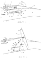
- Figure 1 of the accompanying drawings shows a known example of realization of a thrust reverser of this type, applied as shown in the partial schematic perspective view of Figure 2, to a turbofan engine.
- the reversing device consists of doors 7 forming a movable part 2 and constituting in the inactive position, during direct jet operation, part of the enclosure exterior, and of a fixed structure carrying out this rollover outside upstream of the doors, through an upstream part 1 downstream doors by a downstream part 3 and between doors 7 by through beams 18 which connect the downstream part 3 of the outer casing at the upstream part 4 of the outer casing.
- the doors 7 are mounted on a circumference of the cowling outside and are pivotally mounted in an area intermediate their side walls on the beams 18 located on either side of these doors, these walls side constituting with the upstream and downstream walls, the walls which connect the outer part 9 of the doors 7, which constitute a part of the external wall of the nacelle, to the inner part 11 of the doors 7, which constitute a part of the outer wall of the duct.
- the upstream part 1 of fixed structure includes a front frame 6 which serves as a support for the movement control means doors 7, constituted for example by jacks 8.
- the doors 7 swing in such a way that the part of the doors located downstream of the pivots, comes more or less completely obstruct the duct, and such so that the upstream part of the doors clears a passage in the outer casing so as to allow the flow secondary to be channeled radially with respect to the axis of the leads.
- the upstream part of the doors 7 projects the outside of the outer casing for reasons of passage dimensioning which must be able to leave pass this flow without compromising engine operation.
- the pivot angle of the doors is adjusted so that allow passage of the flow and so as to remove the thrust of this flow, or even begin to generate a counter thrust by generating a component of the flow diverted towards upstream.
- the doors 7 are also provided in their upstream part a spoiler 13 projecting forward, when the doors 7 are deployed, with respect to the internal face of the doors, so as to divert the flow upstream and complete to obtain the counter-thrust component.
- FR 1,482,538 or by FR-A-2,030,034.
- the spoilers 13 protrude relative to the internal face 11 of doors 7, even in direct jet without doing so protrusion in the conduit which is in this example provided with cavities 5 slightly detrimental to the performance of the engine while the reversing device becomes extremely simple.
- spoilers and deflection edges also make it possible to optimize the direction of ejection of the flow as indicated by FR-A-2 680 547.
- the type of thrust reverser described above has the major disadvantage that, for reasons imposed by aerodynamic design constraints of the passage of the flow in the passages cleared by the upstream part of these doors, the pressure of the duct exerts on these doors a action which tends to open them, in fact, the total section of these passages must be greater than the section of the duct in a plane located upstream of the doors, this because of the pressure losses caused by the flow deflection, this in the case where the leakage section (downstream part of the duct not obstructed by the downstream part of the doors), is minimized by so as to obtain a suitable counter-thrust.
- the object of the invention is to propose a means which allows increase safety and / or reduce mass of this type or improve the reverse jet performance.
- EP-A-0 413 635 describes an inverter with doors associated with a upstream panel with fixed pivots located in the parts lateral or beams of the fixed structure of the inverter and driven by the door by means of a connecting member or connecting rod in the same direction of rotation as said doors.
- Goals are achieved in accordance with the invention by a thrust reverser with pivoting doors of the aforementioned type characterized in that the upstream panel is supported and connected on the one hand by at least one connecting rod to the fixed structure of the reverser and on the other hand by at least one connecting rod to the door associated so that the faces of the upstream panel in all operating phases retain a orientation parallel to the layers of the flow in contact with said panel.
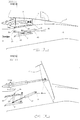
- a thrust reverser likely to perform in the relevant flight phases of an aircraft a reverse flow of the associated turbojet includes the main parts known and previously described in a known embodiment, with reference Figures 1 and 2.
- the fixed structure upstream 1 the doors 7 comprising the external part 9, the inner part 11, a spoiler 13 and associated with a jack 8, and the downstream part 3.
- the seal is ensured by a seal 25 placed between the upstream panel 22, part of the fixed structure 1 and a part of door 7.
- the examples shown represent this gasket installed on the upstream panel 22 but note that a reverse assembly can also be used, i.e. that the part of the fixed structure 1 and the part of the door 7 can receive and contain, in a position allowing the continuity of the lines, the joint (s).
- the panel 22 is retained and operated by one or more sets of spreader 30 and connecting rod 35.
- Their pivot points 24 and 36 are placed on the fixed structure 1, generally at the beams 18 of the inverter. They are located in an area between the pivot 20 of the door 7 and the upstream of the beam 18.
- the opposite ends of the connecting rods 30 and 35 are connected to the panel 22 at articulation points 31 and 37. These articulation points are located between downstream and upstream of the panel 22 according to the desired effect.
- the four points articulation 24, 31, 36 and 37 of the connecting rod assembly, spreader and panel form a quadrilateral. This arrangement allows the flow circulating in the jet stream direct to apply its action on the entire surface of the panel 22 and keep it pressed against the fixed structure 1 and against door 7 according to FIG. 3.
- the direction of swinging of the upstream panel 22 makes it possible to add a closing component of door 7 via of the connecting rod 34.
- the upstream panel 22 is driven in swinging by the lifter (s) leading (s) 30 and the or the guide rod (s) 35.
- the intermediate rod 34 transmits the operation from point 33 to door 7, to point 32 on the lifting beam 30.
- orientation of said upstream panel 22 in reverse jet position is according to the desired effect depending on the positions of pivot points 24 and 36 on the fixed structure 1, positions of the pivot points 31 and 37 on the panel 22, lengths of rods 30, 34 and 35 and locations of pivots 32 and 33 of the intermediate link 34.
- the remarkable effect in the position in reverse jet mode is that the orientation of the upstream panel 22 can be optimized to stay, if desired, as close as possible to flow 14 in order to minimize the disturbances caused by the presence of said panel in the stream. It should be noted that appropriate shapes of the upstream and downstream parts of the upstream panel as well as its internal wall 43 can also allow optimal flow guidance in the reverse jet position.
- the operation of the lifter 30 is directly controlled by a roller 47 integral with door 7 and moving in a groove 29 made in said spreader 30.
- a lifter 27 is equipped in its downstream part of a toothed sector 16. It is driven by through another toothed sector 28, integral with the door 7, at its pivot 20. Said lifting beam 27 is integral with the fixed structure at pivot point 24 and connected to the upstream panel 22 at the drive point 31.
- the guide rod 35 has its point fixed pivot 36 on the fixed structure 1, and is connected to the upstream panel at point 37.
- FIGS. 9 and 10 show an embodiment identical to that described in FIGS. 3 and 4, except the exception of the pivot point 36 of the guide rod 35 which is in this configuration integral with the door 7.
- Figures 11 and 12 show another example drive to move the panel 22 downstream upstream.
- FIG. 13 a second embodiment of the invention shown in Figures 13, 14 and 18, we can dissociate the operation of the panel 22 from that of the door 7.
- the drive of said panel 22 is carried out by one or several independent jack (s) 40 or by another independent system known to those skilled in the art. He can be connected to point 39 on the side walls 19 of the structure fixed 1.
- One or more cylinders 40 can be installed in the beam 18, and drive the panel 22 through a return of one of the connecting rods 23 or 35 inside said beam 18.
- a single cylinder 40 can synchronize the operation of two panels 22.
- the jack 40 can be synchronized with the inverter system or fully independent.
- the panel 22 thus made free with respect to the door 7 can be operated at any stage of the reverse jet phase and thus fulfill the optimal conditions according to the desired performance.
- the displacement of the panel 22 can easily be adjustable since there is no requirement for kinematics as encountered in the other systems.
- the operation of the panel 22 may not even be actuated depending on the desired reverse jet effect.
- These kinematics can be different from one door to another, and thus contribute to the control of the jets leaving the reverser.
- Certain variants can be applied to this embodiment corresponding to FIGS. 13, 14 and 18.
- One of the sets of connecting rods 23 or 35 can be telescopic or be replaced by jacks.
- the jack 40 can be deleted if all the connecting rods 23 and 35 are replaced by jacks.
- FIG. 15 Complementary provisions of the realization previously described with reference in particular to FIGS. 3 and 4 are shown in FIG. 15, in which the panel upstream 22 is shown in direct jet position 22a and in reverse jet position 22b, the control elements 34-30 and orientation of the upstream panel 22 are located between a wall lateral 19 of the fixed structure, and at least one of the two side walls 17 of the door.
- Spreaders and connecting rods are shown parallel to the axis of door 7 and between them, and their articulated points aligned. For reasons kinematics or size, said points joints may not be aligned and or the connecting rods may have a slight impact with the axis of the door 7.
- the axis of rotation 240 passing through the pivot points 24 is not parallel to axis 200 symbolizing the axis of rotation of the door 7 between its two pivot points.
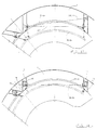
- one or more walls 44 can be associated with the upstream panel 22 by through one or more supports 45 for the purpose optimize the aerodynamic / resistance compromise structural, and improve aerodynamic performance and piloting the reverse jet.
- the wall (s) 44 are arranged in the direction longitudinal of the motor axis, parallel or not with respect to the outer wall 46 of the upstream panel 22. They have a profile aerodynamics adapted to the desired effect in reverse jet mode.
- the supports 45 are arranged in the longitudinal direction parallel or inclined to the motor axis, they can be tilted or normal to the wall external 46 of the upstream panel 22. They have profiles aerodynamics adapted to the desired effect in jet mode inverted, or to the desired jet piloting.
- the wall (s) 44 as well as the support (s) 45 can be of number, shape, height and / or width different from one panel 22 to another and between them. Their width can change depending on the span of panel 22.
- the wall 44 can occupy all or part of the external wall 46 of the panel according to the desired goal.
- the wall 44 can also receive on its external surface one or more supports 45 allowing the mounting of one or more other walls as a function of the structural strength and the aerodynamic performance sought.
- Some of the arrangements and variants of the invention described above can of course be used alone or in combination with one another on a thrust reverser. In particular with a view to improving the control of the sheets during an operation in reverse thrust, these associated arrangements make it possible to have doors 7 associated with panels 22 having different positions and opening angles between them.
Landscapes
- Engineering & Computer Science (AREA)
- Chemical & Material Sciences (AREA)
- Combustion & Propulsion (AREA)
- Mechanical Engineering (AREA)
- General Engineering & Computer Science (AREA)
- Structures Of Non-Positive Displacement Pumps (AREA)
- Superstructure Of Vehicle (AREA)
Claims (11)
- Schubumkehrvorrichtung für ein Zweikreis-Turbostrahltriebwerk mit schwenkbaren Klappen (7), die sich in Schließstellung im Direkstrahlbetrieb in die Außenwand der Strömungsleitung hinter dem Rotor des Turbostrahltriebwerks einfügen und unter der Einwirkung einer Stellantriebsvorrichtung (8) so verschwenkbar sind, daß sie im Schubumkehrbetrieb Hindernisse zum Ablenken der Strömung bilden, wobei der stromaufwärtige Teil jeder Klappe (7) in Schließstellung mit einer stromaufwärtigen Auskleidung (22) hinterlegt ist, die eine Glättung des Fluidstroms im Direkstrahlbetrieb ermöglicht, dadurch gekennzeichnet, daß die stromaufwärtige Auskleidung (22) einerseits durch wenigstens ein Pleuel (35) mit der festen Struktur (1) der Schubumkehrvorrichtung und andererseits durch wenigstens ein Pleuel (34) mit der zugehörigen Klappe (7) verbunden ist.
- Schubumkehrvorrichtung für ein Zweikreis-Turbostrahltriebwerk nach Anspruch 1, bei der die Abstützung der stromaufwärtigen Auskleidung (22) so ausgebildet ist, daß die Seiten der stromaufwärtigen Auskleidung (22) in allen Betriebsphasen eine Orientierung parallel zu den Strömungsschichten (14) beibehalten, die mit der Auskleidung (22) in Kontakt stehen.
- Schubumkehrvorrichtung für ein Zweikreis-Turbostrahltriebwerk nach Anspruch 1 oder 2, bei der die stromaufwärtige Auskleidung (22) von wenigstens einer Baugruppe gehalten und bewegt wird, die ein Pleuel (25) und ein Ausgleichsgestänge (30) umfaßt, wobei das Pleuel (35) mit einem Ende (37) an der Auskleidung (22) und mit dem anderen Ende (36) an der festen Struktur (1) der Schubumkehrvorrichtung angelenkt ist, und wobei das Ausgleichsgestänge (30) um einen mit der festen Struktur (1) fest verbundenen Drehzapfen (24) drehbar ist und mit einem Ende (31) an der Auskleidung (22) und mit dem anderen Ende (32) an einem Zwischenpleuel (24) angelenkt ist, das seinerseits mit seinem anderen Ende (33) an der Klappe angelenkt ist, wobei die Positionen der Auskleidung (22) in Abhängigkeit von den angestrebten Wirkungen durch die Längen der Pleuel (35, 30, 34) und die Orte der Gelenkverbindungen (24, 36, 37, 31, 32, 33) festgelegt sind.
- Schubumkehrvorrichtung für ein Zweikreis-Turbostrahltriebwerk nach Anspruch 1 oder 2, bei der die stromaufwärtige Auskleidung (22) von wenigstens einer Baugruppe gehalten und bewegt wird, die ein Pleuel (25) und ein Ausgleichsgestänge (30) umfaßt, wobei das Pleuel (35) mit einem Ende (37) an der Auskleidung (22) und mit dem anderen Ende (36) an der festen Struktur (1) der Schubumkehrvorrichtung angelenkt ist, und wobei das Ausgleichsgestänge (30) um einen mit der festen Struktur (1) fest verbundenen Drehzapfen (24) drehbar ist und mit einem Ende (31) mit der Auskleidung (22) und mit dem anderen Ende, das einen Schlitz (29) aufweist, mit einer Leitrolle (47) gelenkig verbunden ist, die mit der Klappe (7) fest verbunden ist.
- Schubumkehrvorrichtung für ein Zweikreis-Turbostrahltriebwerk nach Anspruch 1 oder 2, bei der die stromaufwärtige Auskleidung (22) von wenigstens einer Baugruppe gehalten und bewegt wird, die ein Pleuel (25) und ein Ausgleichsgestänge (30) umfaßt, wobei das Pleuel (35) mit einem Ende (37) an der Auskleidung (22) und mit dem anderen Ende (36) an der festen Struktur (1) der Schubumkehrvorrichtung angelenkt ist, und wobei das Ausgleichsgestänge (30) um mit der festen Struktur (1) fest verbundenen Drehzapfen (24) drehbar ist und mit einem Ende (31) an der Auskleidung (22) angelenkt ist und an ihrem anderen Ende einen Zahnsektor (16) aufweist, der mit einem anderen Zahnsektor (28) zusammenwirkt, der mit dem Drehzapfen (20) der Klappe (7) fest verbunden ist,
- Schubumkehrvorrichtung für ein Zweikreis-Turbostrahltriebwerk nach Anspruch 1 oder 2, bei der die stromaufwärtige Auskleidung (22) von wenigstens einer Baugruppe gehalten und bewegt wird, die ein Pleuel (25) und ein Ausgleichsgestänge (30) umfaßt, wobei das Pleuel (35) mit einem Ende (37) an der Auskleidung (22) und mit dem anderen Ende (36) an der festen Struktur (1) angelenkt ist, und wobei das Ausgleichsgestänge (30) um einen mit der festen Struktur (1) fest verbundenen Drehzapfen (24) drehbar ist und mit einem Ende (31) an der Auskleidung (22) und mit dem anderen Ende (32) an einem Zwischenpleuel (34) angelenkt ist, das seinerseits mit seinem anderen Ende an der Klappe (7) angelenkt ist.
- Schubumkehrvorrichtung für ein Zweikreis-Turbostrahltriebwerk nach einem der Ansprüche 1 oder 2, dadurch gekennzeichnet, daß die stromaufwärtige Auskleidung (22) unabhängig von der Klappe (7) von wenigstens einem Antriebszylinder (40) angetrieben wird, der an der festen Struktur (1) der Schubumkehrvorrichtung befestigt ist.
- Schubumkehrvorrichtung für ein Zweikreis-Turbostrahltriebwerk nach einem der Ansprüche 1 bis 7, bei der wenigstens einer der Pleuel-Gelenkpunkte (24, 36), die an der festen Struktur (1) der Schubumkehrvorrichtung angeordnet sind, auf den Längsträgern (18) der Schubumkehrvorrichtung liegen.
- Schubumkehrvorrichtung für ein Zweikreis-Turbostrahltriebwerk nach einem der Ansprüche 1 oder 2, dadurch gekennzeichnet, daß die stromaufwärtige Auskleidung (22) von wenigstens einer Baugruppe getragen wird, die einen stromaufwärtigen Antriebszylinder und einen stromabwärtigen Antriebszylinder umfaßt, die an der festen Struktur (1) der Schubumkehrvorrichtung befestigt sind und die Auskleidung (22) unabhängig von der Klappe (7) antreiben.
- Schubumkehrvorrichtung für ein Zweikreis-Turbostrahltriebwerk nach einem der Ansprüche 1 bis 7, bei der die stromaufwärtige Auskleidung (22a) einen Ausschnitt (21) besitzt, der eine Bewegung zwischen der Auskleidung (22b) und der der benachbarten Klappe (7) der Schubumkehrvorrichtung zugeordneten Auskleidung (42b) ohne gegenseitige Behinderung ermöglicht.
- Schubumkehrvorrichtung für ein Zweikreis-Turbostrahltriebwerk nach einem der Ansprüche 1 bis 10, bei der die stromaufwärtige Auskleidung (22), die aus einem Sandwichelement besteht, das aus einer Innenwand (26) und einer Außenwand (46) zusammengesetzt ist, die miteinander verbunden sind, außerdem wenigstens eine zusätzliche Außenwand Wand (44) aufweist, die durch Stützen (45) mit der Außenwand (46) verbunden ist.
Applications Claiming Priority (2)
| Application Number | Priority Date | Filing Date | Title |
|---|---|---|---|
| FR9606046A FR2748779B1 (fr) | 1996-05-15 | 1996-05-15 | Inverseur de poussee de turboreacteur a portes associees a un panneau amont |
| FR9606046 | 1996-05-15 |
Publications (2)
| Publication Number | Publication Date |
|---|---|
| EP0807752A1 EP0807752A1 (de) | 1997-11-19 |
| EP0807752B1 true EP0807752B1 (de) | 2003-08-13 |
Family
ID=9492155
Family Applications (1)
| Application Number | Title | Priority Date | Filing Date |
|---|---|---|---|
| EP97401076A Expired - Lifetime EP0807752B1 (de) | 1996-05-15 | 1997-05-15 | Schubumkehrvorrichtung mit beweglichen Auskleidungen in den Klappen |
Country Status (8)
| Country | Link |
|---|---|
| US (1) | US5899059A (de) |
| EP (1) | EP0807752B1 (de) |
| JP (1) | JPH1081300A (de) |
| CA (1) | CA2204824A1 (de) |
| DE (1) | DE69724033T2 (de) |
| FR (1) | FR2748779B1 (de) |
| RU (1) | RU2139435C1 (de) |
| WO (1) | WO1997043536A1 (de) |
Families Citing this family (16)
| Publication number | Priority date | Publication date | Assignee | Title |
|---|---|---|---|---|
| FR2764340B1 (fr) * | 1997-06-05 | 1999-07-16 | Hispano Suiza Sa | Inverseur de poussee de turboreacteur a portes munies d'un becquet mobile a entrainement optimise |
| US7278258B2 (en) * | 2004-11-12 | 2007-10-09 | Honeywell International, Inc. | Floating flexible firewall seal |
| US20060150612A1 (en) * | 2005-01-12 | 2006-07-13 | Honeywell International Inc. | Thrust vector control |
| US8015797B2 (en) | 2006-09-21 | 2011-09-13 | Jean-Pierre Lair | Thrust reverser nozzle for a turbofan gas turbine engine |
| US7735778B2 (en) | 2007-11-16 | 2010-06-15 | Pratt & Whitney Canada Corp. | Pivoting fairings for a thrust reverser |
| US8052085B2 (en) | 2007-11-16 | 2011-11-08 | The Nordam Group, Inc. | Thrust reverser for a turbofan gas turbine engine |
| US8052086B2 (en) | 2007-11-16 | 2011-11-08 | The Nordam Group, Inc. | Thrust reverser door |
| US8091827B2 (en) | 2007-11-16 | 2012-01-10 | The Nordam Group, Inc. | Thrust reverser door |
| US8172175B2 (en) | 2007-11-16 | 2012-05-08 | The Nordam Group, Inc. | Pivoting door thrust reverser for a turbofan gas turbine engine |
| US8051639B2 (en) * | 2007-11-16 | 2011-11-08 | The Nordam Group, Inc. | Thrust reverser |
| US20130202402A1 (en) * | 2010-02-15 | 2013-08-08 | Alan Roy Stuart | Articulating slider track |
| US9217390B2 (en) | 2012-06-28 | 2015-12-22 | United Technologies Corporation | Thrust reverser maintenance actuation system |
| EP2971729B1 (de) * | 2013-03-14 | 2019-02-27 | United Technologies Corporation | Gasturbinenmotor und lüftungsverfahren |
| US20160025038A1 (en) * | 2013-03-15 | 2016-01-28 | United Technologies Corporation | Pivot door thrust reverser |
| CN111636978B (zh) * | 2020-06-16 | 2021-06-18 | 南京航空航天大学 | 一种适用于涡轮基循环组合发动机的流量调节机构 |
| EP4417954B1 (de) * | 2023-02-17 | 2026-04-01 | Airbus Operations (S.A.S.) | Antistatisches druckmessrechen |
Family Cites Families (16)
| Publication number | Priority date | Publication date | Assignee | Title |
|---|---|---|---|---|
| US3279182A (en) * | 1965-06-07 | 1966-10-18 | Gen Electric | Thrust reverser |
| FR1482538A (fr) * | 1965-06-07 | 1967-05-26 | Gen Electric | Inverseur de poussée |
| GB1181746A (en) * | 1968-06-19 | 1970-02-18 | Rolls Royce | Thrust Reverser for Jet Propulsion Plant |
| US3598318A (en) * | 1970-04-10 | 1971-08-10 | Boeing Co | Movable acoustic splitter for nozzle area control and thrust reversal |
| US3601992A (en) * | 1970-06-10 | 1971-08-31 | Rohr Corp | Thrust reversing apparatus |
| US3605411A (en) * | 1970-07-01 | 1971-09-20 | Rohr Corp | Thrust reversing apparatus |
| US3739582A (en) * | 1972-04-13 | 1973-06-19 | Rohr Industries Inc | Thrust reversing apparatus |
| US3831376A (en) * | 1973-02-05 | 1974-08-27 | Boeing Co | Thrust reverser |
| FR2618853B1 (fr) * | 1987-07-29 | 1989-11-10 | Hispano Suiza Sa | Inverseur de poussee de turboreacteur muni d'un deflecteur mobile de porte |
| RU1563310C (ru) * | 1988-04-19 | 1994-05-15 | Акционерное общество "Авиадвигатель" | Реверсивное устройство наружного контура турбореактивного двухконтурного двигателя |
| FR2651021B1 (fr) * | 1989-08-18 | 1994-05-06 | Hispano Suiza Sa | Inverseur de poussee de turboreacteur, a portes associees a un panneau amont |
| US5039171A (en) * | 1989-08-18 | 1991-08-13 | Societe Anonyme Dite Hispano-Suiza | Multi-panel thrust reverser door |
| FR2680547B1 (fr) * | 1991-08-21 | 1993-10-15 | Hispano Suiza | Inverseur de poussee de turboreacteur ayant un bord de deviation a courbure evolutive. |
| FR2738291B1 (fr) * | 1995-09-06 | 1997-09-26 | Hispano Suiza Sa | Inverseur de poussee de turboreacteur a portes associees a un panneau amont formant ecope |
| FR2745035B1 (fr) * | 1996-02-15 | 1998-04-03 | Hispano Suiza Sa | Inverseur de poussee de turboreacteur a portes associees a un panneau amont |
| US5806302A (en) * | 1996-09-24 | 1998-09-15 | Rohr, Inc. | Variable fan exhaust area nozzle for aircraft gas turbine engine with thrust reverser |
-
1996
- 1996-05-15 FR FR9606046A patent/FR2748779B1/fr not_active Expired - Fee Related
-
1997
- 1997-05-08 CA CA002204824A patent/CA2204824A1/fr not_active Abandoned
- 1997-05-14 US US08/856,146 patent/US5899059A/en not_active Expired - Fee Related
- 1997-05-15 WO PCT/FR1997/000862 patent/WO1997043536A1/fr not_active Ceased
- 1997-05-15 JP JP9126037A patent/JPH1081300A/ja active Pending
- 1997-05-15 RU RU98102404A patent/RU2139435C1/ru active
- 1997-05-15 EP EP97401076A patent/EP0807752B1/de not_active Expired - Lifetime
- 1997-05-15 DE DE69724033T patent/DE69724033T2/de not_active Expired - Fee Related
Also Published As
| Publication number | Publication date |
|---|---|
| DE69724033T2 (de) | 2004-06-09 |
| JPH1081300A (ja) | 1998-03-31 |
| FR2748779B1 (fr) | 1998-06-19 |
| CA2204824A1 (fr) | 1997-11-15 |
| WO1997043536A1 (fr) | 1997-11-20 |
| EP0807752A1 (de) | 1997-11-19 |
| FR2748779A1 (fr) | 1997-11-21 |
| DE69724033D1 (de) | 2003-09-18 |
| RU2139435C1 (ru) | 1999-10-10 |
| US5899059A (en) | 1999-05-04 |
Similar Documents
| Publication | Publication Date | Title |
|---|---|---|
| EP0848153B1 (de) | Schubumkehrvorrichtung für ein Strahltriebwerk mit Umlenkklappen und an der festen Trägerstruktur behalteten Leitflächen | |
| CA1329487C (fr) | Inverseur de poussee de turboreacteur, a portes pivotantes equilibrees | |
| CA2225608C (fr) | Inverseur de poussee de turboreacteur a double flux a coquilles aval | |
| EP0807752B1 (de) | Schubumkehrvorrichtung mit beweglichen Auskleidungen in den Klappen | |
| EP0777045B1 (de) | Schubumkehrvorrichtung mit Klappen und an dem Hinterteil verbundenen Hilfsklappen | |
| CA2204589C (fr) | Inverseur de poussee de turboreacteur a portes munies d'aubes deflectrices | |
| EP0882881B1 (de) | Schubumkehrvorrichtung für ein Strahltriebwerk dessen Umkehrklappen mit optimal entfaltbaren Leitflächen versehen sind | |
| FR2752017A1 (fr) | Inverseur de poussee de turboreacteur a portes formant ecopes | |
| EP0761957A1 (de) | Schubumkehrvorrichtung für ein Strahltriebwerk von mit dem Vorderteil verbundenen Klappen | |
| EP0807753B1 (de) | Schubumkehrvorrichtung eines Strahltriebwerkes mit an der Vorseite der Klappen verbundenem Wandteil | |
| FR2754565A1 (fr) | Inverseur de poussee a portes a debit de fuite controle | |
| CA2185300A1 (fr) | Inverseur de poussee de turboreacteur a portes associees a un panneau primaire | |
| EP0864740A1 (de) | Schubumkehrvorrichtung eines Turbofans mit federbelasteter Klappenaussenwand | |
| FR2751377A1 (fr) | Inverseur de poussee de turboreacteur a portes comportant un panneau coulissant | |
| EP0728933B1 (de) | Schubumkehrvorrichtung mit dem Hinterteil verbundenen Klappen |
Legal Events
| Date | Code | Title | Description |
|---|---|---|---|
| PUAI | Public reference made under article 153(3) epc to a published international application that has entered the european phase |
Free format text: ORIGINAL CODE: 0009012 |
|
| 17P | Request for examination filed |
Effective date: 19970603 |
|
| AK | Designated contracting states |
Kind code of ref document: A1 Designated state(s): DE FR GB IT |
|
| 17Q | First examination report despatched |
Effective date: 20020128 |
|
| GRAH | Despatch of communication of intention to grant a patent |
Free format text: ORIGINAL CODE: EPIDOS IGRA |
|
| GRAH | Despatch of communication of intention to grant a patent |
Free format text: ORIGINAL CODE: EPIDOS IGRA |
|
| RAP1 | Party data changed (applicant data changed or rights of an application transferred) |
Owner name: HUREL HISPANO LE HAVRE |
|
| GRAA | (expected) grant |
Free format text: ORIGINAL CODE: 0009210 |
|
| AK | Designated contracting states |
Designated state(s): DE FR GB IT |
|
| REG | Reference to a national code |
Ref country code: GB Ref legal event code: FG4D Free format text: NOT ENGLISH |
|
| REF | Corresponds to: |
Ref document number: 69724033 Country of ref document: DE Date of ref document: 20030918 Kind code of ref document: P |
|
| GBT | Gb: translation of ep patent filed (gb section 77(6)(a)/1977) |
Effective date: 20031031 |
|
| PG25 | Lapsed in a contracting state [announced via postgrant information from national office to epo] |
Ref country code: GB Free format text: LAPSE BECAUSE OF NON-PAYMENT OF DUE FEES Effective date: 20040515 |
|
| PLBE | No opposition filed within time limit |
Free format text: ORIGINAL CODE: 0009261 |
|
| STAA | Information on the status of an ep patent application or granted ep patent |
Free format text: STATUS: NO OPPOSITION FILED WITHIN TIME LIMIT |
|
| 26N | No opposition filed |
Effective date: 20040514 |
|
| PG25 | Lapsed in a contracting state [announced via postgrant information from national office to epo] |
Ref country code: DE Free format text: LAPSE BECAUSE OF NON-PAYMENT OF DUE FEES Effective date: 20041201 |
|
| GBPC | Gb: european patent ceased through non-payment of renewal fee |
Effective date: 20040515 |
|
| PG25 | Lapsed in a contracting state [announced via postgrant information from national office to epo] |
Ref country code: FR Free format text: LAPSE BECAUSE OF NON-PAYMENT OF DUE FEES Effective date: 20050131 |
|
| REG | Reference to a national code |
Ref country code: FR Ref legal event code: ST |
|
| PG25 | Lapsed in a contracting state [announced via postgrant information from national office to epo] |
Ref country code: IT Free format text: LAPSE BECAUSE OF NON-PAYMENT OF DUE FEES;WARNING: LAPSES OF ITALIAN PATENTS WITH EFFECTIVE DATE BEFORE 2007 MAY HAVE OCCURRED AT ANY TIME BEFORE 2007. THE CORRECT EFFECTIVE DATE MAY BE DIFFERENT FROM THE ONE RECORDED. Effective date: 20050515 |