EP0807595B1 - Sorter and image forming apparatus having the same - Google Patents
Sorter and image forming apparatus having the same Download PDFInfo
- Publication number
- EP0807595B1 EP0807595B1 EP97107726A EP97107726A EP0807595B1 EP 0807595 B1 EP0807595 B1 EP 0807595B1 EP 97107726 A EP97107726 A EP 97107726A EP 97107726 A EP97107726 A EP 97107726A EP 0807595 B1 EP0807595 B1 EP 0807595B1
- Authority
- EP
- European Patent Office
- Prior art keywords
- sheet
- printed sheet
- printed
- printing
- sorter
- Prior art date
- Legal status (The legal status is an assumption and is not a legal conclusion. Google has not performed a legal analysis and makes no representation as to the accuracy of the status listed.)
- Expired - Lifetime
Links
Images


Classifications
-
- B—PERFORMING OPERATIONS; TRANSPORTING
- B65—CONVEYING; PACKING; STORING; HANDLING THIN OR FILAMENTARY MATERIAL
- B65H—HANDLING THIN OR FILAMENTARY MATERIAL, e.g. SHEETS, WEBS, CABLES
- B65H39/00—Associating, collating, or gathering articles or webs
- B65H39/10—Associating articles from a single source, to form, e.g. a writing-pad
- B65H39/11—Associating articles from a single source, to form, e.g. a writing-pad in superposed carriers
-
- B—PERFORMING OPERATIONS; TRANSPORTING
- B65—CONVEYING; PACKING; STORING; HANDLING THIN OR FILAMENTARY MATERIAL
- B65H—HANDLING THIN OR FILAMENTARY MATERIAL, e.g. SHEETS, WEBS, CABLES
- B65H2511/00—Dimensions; Position; Numbers; Identification; Occurrences
- B65H2511/10—Size; Dimensions
- B65H2511/13—Thickness
-
- B—PERFORMING OPERATIONS; TRANSPORTING
- B65—CONVEYING; PACKING; STORING; HANDLING THIN OR FILAMENTARY MATERIAL
- B65H—HANDLING THIN OR FILAMENTARY MATERIAL, e.g. SHEETS, WEBS, CABLES
- B65H2511/00—Dimensions; Position; Numbers; Identification; Occurrences
- B65H2511/20—Location in space
- B65H2511/23—Coordinates, e.g. three dimensional coordinates
-
- B—PERFORMING OPERATIONS; TRANSPORTING
- B65—CONVEYING; PACKING; STORING; HANDLING THIN OR FILAMENTARY MATERIAL
- B65H—HANDLING THIN OR FILAMENTARY MATERIAL, e.g. SHEETS, WEBS, CABLES
- B65H2551/00—Means for control to be used by operator; User interfaces
- B65H2551/10—Command input means
Definitions
- the present invention relates to a sheet post-processing unit such as a sorter for distributing and accommodating printed sheets discharged from the image forming machine, and to an image forming apparatus having the sheet post processing unit and an image forming machine such as a copying machine, a printer and the like for forming images on a printing sheet.
- a sheet post-processing unit such as a sorter for distributing and accommodating printed sheets discharged from the image forming machine
- an image forming apparatus having the sheet post processing unit and an image forming machine such as a copying machine, a printer and the like for forming images on a printing sheet.
- Sheet post-processing units for distributing printed sheets which have images formed thereon and discharged from a stencil printing machine have heretofore been developed and put to practical use.
- Sheet post-processing units of the sorts mentioned above are desired to be devised so that while every possible effort is made for size reduction, a larger number of printed sheet of, for instance papers may be distributable.
- a sheet post-processing unit of a fixed bin type a plurality of bins are fixedly arranged in the vertical direction of a casing and conveyer units fitted with fans and blowers are installed in the vertical direction of the plurality of bins and besides indexers as sheet guide means for carrying printed sheets into the corresponding bins are moved up and down vertically along travel routes of the conveyer units. Therefore, an attempt has been made to reduce the size of the whole apparatus by decreasing the dimension thereof in the depth direction. With respect to the conveyer unit, moreover, the diameter of a corner portion at both ends of a belt has also been designed for its size to be minimized.
- the following problems still exist because various types of sheet are used as printing sheet in the stencil printing machine cooperating with aforementioned sheet post-processing unit.
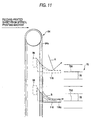
- the travel route is largely curved in the corner portion of a belt 94a in a belt conveyer unit 94 as shown in Fig. 11.
- the uppermost bin 78A is first used for accommodating the printed sheet in a case where the printed sheet discharged from the stencil printing machine and conveyed thereto is ordinary paper. Nevertheless, the firm thick printed paper tends to easily peel off the belt 94a after it has made a U-turn in the corner portion of the belt 94a and passed thereon and it also becomes readily afloat and deviates from the travel route even when a suction unit 96 is employed for drawing the printed paper to the belt. Consequently, the printed paper is conveyed at an acute angle with respect to an indexer 116 as shown by an arrow A of Fig. 11 and caused to strike against the surface of the indexer 116 in a manner sticking therein. Therefore, the printed paper becomes unaccommodated in a target bin 78, which also poses a problem causing a paper jam.
- Document JP 08169628A discloses a control device for controlling the paper sheet conveying speed of a sorter according to the preamble of claim 1.
- the control device comprises an intermediate conveyance device for conveying printed paper sheets to respective bins of a sorter at a specified speed.
- the control device contains paper sheet size detecting sensors for detecting paper sheet sizes, and a paper sheet kind setting means for setting the thickness of paper sheets and paper sheet kinds such as the quality of paper.
- the control device controls the conveyance speed of the paper sheets on the basis of respective signals from the paper sheet size detecting sensors and paper sheet kind setting means so as to avoid paper jamming.
- Document US 3937459 discloses a sorting apparatus having a vertically adjustable sheet receiving and feeding vacuum chamber and a traveling belt mechanism which directs successive sheets to a receiver, which in turn comprises a vacuum chamber and a traveling belt conveyor mechanism for transporting sheets to or past vertically spaced trays. Fingers are shiftable to and from positions to deflect sheets from the transport conveyor and cause sheets to enter the trays.
- an object of the present invention is to provide an image forming apparatus capable of stably conveying printed sheet which tends to deviate from its travel route, and reducing a paper jam percentage.
- a sorter as defined in claim 1 is provided.
- the start position of the working bin is variably controlled according to the information on the thickness of printing sheet such as a printing paper and the like, whereby the printed paper trying to deviate from the travel route can be conveyed stably to the target bin and a paper jam percentage is thus reducible.
- Fig. 1 is an overall block diagram of an image forming apparatus according to the present invention.
- the image forming apparatus comprises a stencil printing machine 1 as an image forming machine and a sorter 2 as a sheet post-processing unit.
- the stencil printing machine 1 has a cylindrical drum 4 rotatably supported with a machine frame (not shown) round the center axis of the cylindrical drum 4.
- the cylindrical drum 4 is porous in structure and has a clamp mechanism 6 on its outer peripheral portion.
- the clamp mechanism 6 retains one end of a stencil 8.
- the cylindrical drum 4 is coupled to and driven by a sprocket 10 installed in a manner coaxial with the center axis 4a.
- An endless belt 12 is used for coupling the sprocket 10 to the driving sprocket 11 cf the drum driving motor 14a of a drum driving mechanism 14.
- the motive power of the drum driving motor 14a of the drum driving mechanism 14 works to drive the cylindrical drum 4 to rotate counterclockwise intermittently or continuously.
- a printing ink supply means 16 is provided in the body of the cylindrical drum 4.
- the printing ink supply means 16 is disposed so that its outer peripheral face is brought into contact with the inner peripheral face of the cylindrical drum 4.
- the printing ink supply means 16 has a squeegee roller 20 capable of rotation round the center axis 18 of the printing ink supply means 16, and a doctor roller 22 extending along the direction of the generating line of the squeegee roller 20 with a predetermined space left with respect to the outer peripheral face of the squeegee roller 20.
- the printing ink supply means 16 is used for supplying printing ink in an ink reservoir 24 onto the inner peripheral face of the cylindrical drum 4 when the squeegee roller 20 is driven to rotate synchronously in the same direction in which the cylindrical drum 4 rotates.
- the printing ink in the ink reservoir 24 is passed through the space between the squeegee roller 20 and the doctor roller 22 as the squeegee roller 20 rotates, when the ink is metered so that a printing ink layer uniform in thickness may be formed on the outer peripheral face of the squeegee roller 20.
- the printing ink layer is applied to the inner peripheral face of the cylindrical drum 4 for printing purposes as the squeegee roller 20 rotates.
- a press roller 26 for pressing a printing sheet P against the cylindrical drum 4 installed opposite to the squeegee roller 20 is positioned outside the cylindrical drum 4.
- a sheet feed tray 28 for setting the printing sheet P, such as a paper, to be fed between the cylindrical drum 4 and the press roller 26 is installed in a left-hand diagonally-downward position.
- the sheet feed tray 28 is moved up and down by a driving unit (not shown) in proportion to the quantity of stacked the printing sheets P thus set thereon.
- a sheet feed mechanism 30 is positioned in the proximity of the sheet feed tray 28.
- the sheet feed mechanism 30 has a sheet feed roller 32 made of, for example, rubber and a pair of timing rollers 34.
- the sheet feed roller 32 picks up the uppermost sheet P to be printed out of those stacked on the paper feed tray 28 one by one and conveys that printing sheet P toward the timing roller side 34.
- the timing rollers 34 While temporarily holding the printing sheet P conveyed from the sheet feed roller 32 in such a state as to form a predetermined roller-to-roller loop, the timing rollers 34 rotate at predetermined timing in synchronization with the rotation of the cylindrical drum 4 in order to convey the printing sheet P toward the cylindrical drum 4 when the printing operation is performed.
- a stencil discharge mechanism 48 is provided round the cylindrical drum 4 and above the sheet feed tray 28.
- the stencil discharge mechanism 48 is used for peeling off the used stencil sheet wound on the outer peripheral face of the cylindrical drum 4 as the cylindrical drum 4 rotates and for accommodating the stencil sheets discharged.
- a printed sheet separating pawl 50 is provided round the cylindrical drum 4 and in a position opposite to the sheet feed mechanism 30.
- the printed sheet separating pawl 50 is used for removing the printed sheet P subjected to printing from the cylindrical drum 4.
- the printed sheet P peeled off by the printed sheet separating pawl 50 is conveyed by a sheet discharge unit 52 toward a sheet discharge port 54.
- the sheet discharge unit 52 has a belt conveyer unit 56 and a suction unit 58; while the printed sheet P peeled by the printed sheet separating pawl 50 off the cylindrical drum 4 is being air-drawn by the suction unit 58, it is conveyed by the belt conveyer unit 56 toward the sheet discharge port 54.
- a sheet discharge tray 60 as a stacker unit is installed in the rear of the sheet discharge port 54. In a selected non-sort mode, which will be described later, the sheet discharge tray 60 accommodates the printed sheet P conveyed from the sheet discharge unit 52.
- a stencil storage unit 62 which is installed above the sheet discharge unit 52, stores the continuous sheet-like stencil 8 wound in the form of a roll.
- a making mechanism 64 is installed between the stencil storage unit 62 and the cylindrical drum 4.
- the making mechanism 64 has a thermal head 66 and a platen roller 68 which is positioned opposite thereto.
- the making mechanism 64 thermally making the printing stencil supplied from the stencil storage unit 62.
- the thermal head 66 though not shown in Fig. 1, has a plurality of heating elements arranged in a line, that is, at fixed intervals in the main scanning direction.
- the heating elements of the thermal head 66 are arranged so that they selectively generate heat in response to the image information signal read by a read unit (not shown).
- the printing stencil made up by the making mechanism 64 is conveyed by a stencil conveyer roller 70 toward the cylindrical drum 4.
- a cutter unit 72 between the making mechanism 64 and the cylindrical drum 4, the cutter unit 72 being used to cut the stencil 8 at a point of time the printing stencil has been wound on the outer peripheral face of the cylindrical drum 4 to a desired extent.
- the sorter 2 has a bin train 76 for accommodating the printed sheets P conveyed from the stencil printing machine 1 in a casing 74 as an outer casing.
- the sorter 2 is arranged so that its multi-stage connection to the stencil printing machine 1 is made possible.
- two sorters 2 namely, a preceding-stage first sorter 2A and a following-stage second sorter 2B, are coupled to the stencil printing machine 1.
- the first and second sorters 2A, 2B are similar in construction except that only the first sorter 2A has an approach conveyer mechanism 80, which will be described later. A detailed description will thereupon be given of the construction of only the first sorter 2A by reference of Fig. 2.
- the bin train 76 has a plurality of bins 78 which are each formed with similar rectangular plate members. These bins 78 are arranged in layers at predetermined intervals d in the height direction (vertical direction) of the casing 74 and fixed to the rear part of the casing 74 inside.
- the approach conveyer mechanism 80 as a first conveyer means for introducing and conveying the printed sheet P from the stencil printing machine 1 into the casing 74 is provided on one side of the casing 74, which side is facing the paper discharge port 54 of the stencil printing machine 1.
- the approach conveyer mechanism 80 has two belt conveyer units: a preceding-stage belt conveyer unit 82 and a following-stage belt conveyer unit 86.
- the belt conveyer units 82, 86 are driven by, for example, DC brushless motors as driving means, respectively. Further, a plurality of suction units 88 in the form of blowers are provided for the respective belt conveyer units 82, 86 at predetermined intervals in the direction in which the printed sheet P is conveyed.
- the preceding-stage belt conveyer unit 82 takes in and conveys the printed sheet P to the following-stage belt conveyer unit 86.
- the following-stage belt conveyer unit 86 conveys the printed sheet P diagonally upward up to a paper introducing port 84 in the upper end portion of one side of the casing 74.
- a bin guide conveyer mechanism 92 as a second conveyer means is provided along the height direction (vertical direction) of the casing 74 under the paper introducing port 84 in the casing 74. Similar to the approach conveyer mechanism 80, the bin guide conveyer mechanism 92 has a belt conveyer unit 94 and suction units 96 and driven by a driving means such as a DC motor. While air-drawing the printed sheet P conveyed from the following-stage belt conveyer unit 86 up to the sheet introducing port 84 by means of the suction units 96, the bin guide conveyer mechanism 92 causes the belt conveyer unit 94 to have the printed sheet P make a U-turn in its curved corner portion and then conveys the printed sheet P downward in the vertical direction of the bin train 76.
- Fig. 3 is a partial enlarged sectional view of the bin guide conveyer unit 92 and the indexer 116, which will be described later, as viewed from the upward; and Fig. 4 is a sectional view taken on line I - I of Fig. 3.
- a comb-like stepped portion 100 is formed in the surface of a frame 98 forming the base of the bin guide conveyer unit 92, so that the printed sheet P is conveyed on the surface thereof.
- through-holes 93 for drawing the printed sheet P are formed at predetermined intervals.
- An endless conveyer belt 94a in the belt conveyer unit 94 is provided for each protrusion 100a of the stepped portion 100 (actually in three places in this embodiment shown).
- Through-holes 101 are formed in the endless conveyer belt 94a in positions opposite to the respective through-holes 93 of the protrusion 100a.
- the air-suction force of the suction unit 96 works to air-draw the printed sheet P via the through-holes 93, 101 to the surface of the conveyer belt 94a and the printed sheet P is conveyed in such a state that it is kept sticking to the surface of the conveyer belt 94a.
- a fan 97 as a blower for pressing the printed sheet P conveyed from the approach conveyer mechanism 80 against the surface of the belt and for sticking the printed sheet P thereon is installed in the proximity of the outer periphery of the top portion of the belt conveyer unit 94.
- a sorter passage conveyer mechanism 102 for conveying the printed sheet P to the second sorter 2B connected to the preceding stage is installed above the bin train 76. Similar to the approach conveyer mechanism 80 and the bin guide conveyer mechanism 92, the sorter passage conveyer mechanism 102 has a belt conveyer unit 104 and a suction unit 106 and driven by, for example, a DC motor as a driving means.
- the sorter passage conveyer mechanism 102 While air-drawing the printed sheet P conveyed by the following-stage belt conveyer unit 86 up to the sheet introducing port 84 by means of the suction units 106, the sorter passage conveyer mechanism 102 discharges the printed sheet P from a sheet discharge port 108 in the upper end portion of the other side face of the casing 74 by means of the belt conveyer unit 104 and conveys the printed sheet P up to the sheet introducing port 84 of the second sorter 2B.
- the sorter passage conveyer mechanism 102 is unnecessary when only one sorter 2 is connected to the stencil printing machine 1.
- a sheet passage sensor 109 is installed on the exit side of the belt conveyer unit 104 in the sorter passage conveyer mechanism 102.
- the sheet passage sensor 109 detects the presence or absence of the passage of the printed sheet P conveyed on the belt conveyer unit 104 before being introduced into the paper introducing port 84 of the second sorter 2B from the paper discharge port 108.
- a sorter switching plate 110 is installed in the proximity of the sheet introducing port 84 on the entrance side of the sorter passage conveyer mechanism 102.
- a sorter switching sensor 112 is installed in the proximity of the sheet introducing port 84 on the entrance side of the sorter switching plate 110. The sorter switching sensor 112 is used for detecting the printed sheet P introduced into the paper introducing port 84 from the approach conveyer mechanism 80 and conveyed therethrough.
- the sorter switching plate 110 is switched under the control of a solenoid 114 which is turned on and off in conformity with not only the number of printed sheet P conveyed to the preceding-stage first sorter 2A connected to the stencil printing machine 1 but also the set mode.
- the sorter switching plate 110, the sorter switching sensor 112 and the solenoid 114 constitute a sorter switching mechanism 115.
- the indexer 116 for causing the printed sheet P to be inserted in the predetermined bin 78 of the bin train 76.
- the indexer 116 has a rectangular support portion 116a substantially equal in width to the bin 78 and remains on standby in the home position HP1 set in a position slightly above the uppermost bin 78 (78A) initially.
- An indexer HP sensor 118 for detecting the presence or absence of the indexer 116 is installed in the home position HP1.
- Plate-like guide members 120 incorporated in the surface of the support portion 116a of the indexer 116 are formed at predetermined intervals in the width direction of the support portion 116a.
- four sets of guide members 120 with two of them as a pair are provided.
- the guide members 120 are uprightly provided in a position corresponding to the recess 100b of the frame 98 of the bin guide conveyer unit 92.
- the surface of the guide member 120 forms a guide plane 120a curving downward from the leading end close to the bin guide conveyer unit 92 up to the trailing end thereof. Further, the leading end portion of the guide member 120 is situated within a recess 100b of the stepped portion 100.
- the indexer 116 is such that both ends of its support member 116a are connected via a driving belt 122 to a driving means such as a DC servo motor.
- a columnar through-hole 116b is formed in a substantially central position of the support member 116a of the indexer 116.
- An indexer sensor 124 formed with a transmission type photosensor is installed in upper and lower positions in the vertical direction of the casing 74 in a manner holding the through-hole 116b therebetween.
- the indexer sensor 124 is used for detecting the printed sheet P passed on the guide plane 120a of the indexer 116, monitoring the situation in which printed paper is unarriving or stagnant on the guide plane 120a of the indexer 116 and also detecting a jam error.
- the indexer 116, the driving belt 122 and the indexer sensors 124 constitute an indexer elevating mechanism 125.
- the indexer sensor 124 may be replaced with a photo-interrupter, which is provided for the indexer 116 and used for detecting the sheet paper P passed on the guide plane 120a of the indexer 116.
- the indexer 116 When the indexer 116 is driven by the DC servo motor as the driving means via the driving belt 122, the tip of the printed sheet P conveyed by the bin guide conveyer unit 92 is peeled off the conveyer belt 94a with the tips of the guide members 120, whereby the printed sheet P is received on the guide plane 120a.
- the indexer sensor 124 detects that the printed sheet P has been accommodated in the bin train 76 for certain, the indexer 116 is made to move by the bin-to-bin 78 pitch with the home position HP1 as a reference position. The printed sheet P is thus inserted in each corresponding bin 78 of the bin train 76 one by one.
- a switching plate 126 is installed on the entrance side of the preceding-stage belt conveyer unit 82 in the approach conveyer mechanism 80.
- the switching plate 126 is so controlled as to be switched when a solenoid 128 is turned on or off in according with the set mode. More specifically, the switching plate 126 is switched so that the printed sheet P is conveyed to the sheet discharge tray 60 of the stencil printing machine 1 when the non-sort mode has been set. On the other hand, the switching plate 126 is switched so that the printed sheet P is conveyed to the first sorter 2A when the mode of using the second sorter 2B has been set. In this case, the switching plate 126 and the solenoid 128 constitute a switching mechanism 129.
- a sheet member 130 which is wound in the form of a roll is installed in a position right above the introduction end side of the uppermost bin 78A.
- One end of the sheet member 130 is fixedly secured to the casing 74 and the other end of the sheet member 130 as an open end is fastened to the indexer 116.
- the sheet member 130 operates to pay out and wind up the sheet, which operation is interlocked with the upward and downward movements of the indexer 116 and also prevents rebounding due to the sub-scan matching board 140 of a matching mechanism 136, which will be described later, when the printed sheet P is accommodated in the bin 78.
- the bin-side surface of the sheet member 130 is made a reference matching plane Y 0 in the sub-scan direction when the sub-scan direction of the printed sheet P inserted in the bin 78 is matched.
- cut portions 132, 134 having predetermined lengths are formed along the direction (sub-scan direction) in which the printed sheet P inserted from the indexer 116 is conveyed and the direction (main scan direction) perpendicular to the direction in which the printed sheet P is conveyed, respectively.
- a matching mechanism 136 for matching the printed sheet P inserted in the bin 78 with predetermined reference matching faces is provided in the positions corresponding to the cut portions 132, 134.
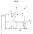
- Fig. 5 is a plan view of the matching mechanism 136.
- the reference matching planes X 0 , Y 0 are set at the left lower corner of Fig. 5. More specifically, the reference matching plane Y 0 in the sub-scan direction is set on the bin-side surface of the sheet member 130 as described above, whereas the reference matching plane X 0 in the main scan direction is set on the inner wall surface of a cover member which can be opened and closed with respect to the casing 74, so that the cover member is made openable when the printed sheet P in the bin 78 is taken out.
- the matching mechanism 136 has a main scan matching plate 138 which is moved in the main scan direction within the cut portion 132 extending in a direction perpendicular to the direction in which the printed sheet P is conveyed, and a sub-scan matching plate 140 which is moved in the sub-scan direction within the cut portion 132 extending therein.
- the outermost position of the cut portion 132 is set to a main scan home position HP2 as a stand-by reference position when the main scan matching plate is moved.
- a main scan HP sensor 142 is installed in the proximity of the outermost position of the cut portion 132, for detecting whether or not the main scan matching plate 138 is positioned at the main scan home position HP2.
- the outermost position of the cut portion 134 is set to a sub-scan home position HP3 as a stand-by reference position when the sub-scan matching plate is moved.
- a sub-scan HP sensor 144 for detecting whether or not the sub-scan matching plate 140 is provided at the sub-scan home position HP3 is installed in the proximity of the outermost position of the cut portion 134.
- the main scan matching plate 138 and the sub-scan matching plate 140 are connected to, for example, pulse motors 137, 139 as driving means, respectively.
- the main scan matching plate 138 is moved in the main scan direction by the pulse quantity with the main scan home position HP2 as a reference when the pulse quantity of the pulse motor as the driving means is determined according to preset sheet main-scan data in conformity with the size of printing sheet.
- the sub-scan matching plate 140 is moved in the sub-scan direction by the pulse quantity with the sub-scan home position HP3 as a reference when the pulse quantity of the pulse motor as the driving means is determined according to preset sheet sub-scan data in conformity with the size of printing sheet.
- the main scan matching plate 138 and the sub-scan matching plate 140 are moved in conformity with the size of the printing sheet, whereby the printed sheet P inserted in each bin 78 of the bin train 76 from the indexer 116 is matched with the reference matching planes X 0 , Y 0 .
- the size of printed sheet that can be accommodated in each bin 78 is restricted by the positional relation between the two matching plates 138, 140 and the positional relation between the HP sensors 142, 144 of the matching plates 138, 140.
- the minimum size of printed sheet that can be accommodated in the bin 78 becomes what is defined by moving the two matching plates 138, 140 as much as possible from the home positions HP2, HP3 up to a position where the matching plates 138, 140 do not interfere with each other.
- the maximum size of printed sheet that can be accommodated in the bin 78 becomes what allows the printed sheet to be accommodated therein without its interference with either HP sensor 142 or 144.
- the stencil printing machine 1 and the sorter 2 thus arranged are connected together by mounting the approach conveyer mechanism 80 on the paper discharge port 54 of the stencil printing machine 1.
- the operation of distributing and accommodating printing sheets in the bin train 76 of the sorter 2 is performed through pressing specific keys provided on the operating panel 146 of the stencil printing machine 1 as will be described below.
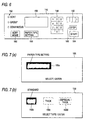
- Fig. 6 shows an operating panel mounted on a stencil printing machine.
- the operating panel 146 is provided with a ten key pad 148, a number-of-sheets LED 150, a display 158 such as a liquid crystal panel, a paper-type setting mode key 159, a sort mode key 160, a mode LED 162, a start key 164 and a stop key 166.
- the ten key pad 148 includes number keys 0 - 9, which are used for setting the number of printing sheets and dimensions in the main scanning and sub-scanning directions of free size in a user mode.
- the number-of-sheets LED 150 displays the number of sheets set through the ten key pad 148.
- the value displayed by the number-of-sheets LED 150 is decremented by one each time the printed sheet P is discharged synchronously during the printing operation performed by the stencil printing machine 1.
- the display 158 displays a paper-type inputting screen in order to determine the start position of the working bin 78. More specifically, an input display screen for displaying a paper-type setting key 158a as a software key shown in Fig. 7(a) appears instead through the operation of the paper-type setting mode key 159.
- the screen is switched over to what displays keys 158b, 158c, 158d as software keys for respectively displaying different paper types of printing sheet (for example, three types of 'standard', 'thick paper' and 'especially thick paper') as shown in Fig. 7(b).
- the display 158 displays an error indication when an error such as a jam occurs, the size of printing sheet P detected by the sheet feed mechanism 30 and the like.
- the paper-type setting mode key 159 is pressed in case that a mode for changing the start position of the working bin 78 in accordance with the thickness of printing paper P to be used in the stencil printing machine 1 is to be selected.
- the sort mode key 160 is pressed when one of the following modes is selected: a non-sort mode in which the printed sheet P is accommodated by using the sheet discharge tray 60, one of the three modes (a sort mode, a group mode and a continuous mode) in which the printed sheet P is accommodated by using the sorter 2.
- the sort mode key 160 is used for sequentially switching the following modes each time it is pressed after the operating panel is supplied with power: namely, from non-sort mode to sort mode, group mode, continuous mode and non-sort mode in a loop.
- the non-sort mode refers to a mode in which the printed sheet P discharged from the paper discharge port 54 of the stencil printing machine 1 is directly discharged onto the sheet discharge tray 60.
- the sort mode refers to a mode in which the printed sheet P discharged from the paper discharge port 54 of the stencil printing machine 1 are page-to-page accommodated in the bins 78 in order to gather the plurality of pages into printed matter.
- the group mode refers to a mode in which the printed sheets P discharged from the sheet discharge port 54 of the stencil printing machine 1 are sorted into groups on a manuscript basis before being accommodated in the bins 78, which makes it possible to sort the printed papers into combinations of 'number of sheets x number of sets' on that manuscript basis.
- the continuous mode refers to a mode in which the printed sheets P discharged from the sheet discharge port 54 of the stencil printing machine 1 are distributed to and accommodated in each bin 78 by one sheet at a time so as to reduce the back printing of printed matter.
- the mode LED 162 displays the mode (the sort mode, the group mode or the continuous mode) selected by the sort mode key 160. In a case where the mode LED 162 displays nothing, the non-sort mode has been selected.
- the start key 164 is pressed when the operation of the stencil printing machine 1 and the sorter 2 is to be performed.
- the stop key 166 is pressed when the operation of the stencil printing machine 1 and the sorter 2 is to be stopped.
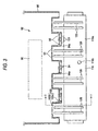
- Fig. 8 is a block diagram illustrating an electrical arrangement of the aforesaid image forming apparatus.
- a control means (CPU) 170 such as a microprocessor is used for controlling each of the mechanisms in the apparatus according to the program stored in a ROM 172.
- a RAM 174 for storing information fed from the operating panel 146 is connected to the control means 170, the information including the number of printing, free size at the time the user mode is set, various sort modes and the like.
- the control means 170 is used for controlling the rotation of the cylindrical drum 4 by issuing a rotation command to the drum driving mechanism 14.
- the control means 170 also issues to the making mechanism 64 a command of making up the stencil 8, to the clamp mechanism 6 a command of retaining/releasing the stencil 8 by/from the cylindrical drum 4, to the stencil discharge mechanism 48 a command of peeling the used stencil 8 off the cylindrical drum 4, and to the sheet feed mechanism 30 a command of performing the operation of feeding the printing sheet P, which operation is interlocked with the drum driving mechanism 14.
- a control unit 176 for controlling the operation of each mechanism of the sorter 2 is provided on the sorter side.
- This control unit 176 and the control means 170 of the stencil printing machine 1 are electrically connected via a cable or the like, so that control information is exchanged therebetween.
- the control unit 176 is used for synchronously controlling the operation of the sorter 2 for successively taking in the printed sheets P discharged one by one from the stencil printing machine 1 according to the control commands from the control means 170 under the control thereof.
- control unit 176 When an error occurs on the part of-the sorter 2, the control unit 176 notifies the occurrence of such an error to the control means 170 and deals with the error according to control instructions from the control means 170.
- control unit 176 issues control commands to the approach conveyer mechanism 80, the bin guide conveyer mechanism 92, the sorter passage conveyer mechanism 102, the sorter switching mechanism 115, the indexer elevating mechanism 125, the switching mechanism 129, the matching mechanism 136 and the like in the sorter 2.
- the printed sheets P discharged from the stencil printing machine 1 are sorted out and accommodated in the corresponding bins 78 of the sorter 2 in conformity with the set mode.
- the operating panel 146 is installed on the stencil printing machine side 1
- a similar operating panel may be installed on the sorter side 2 so as to send set contents resulting from the operation of that operating panel to the control means 170 of the stencil printing machine 1.
- the operating panels 146 may be installed in both stencil printing machine 1 and sorter 2.
- the paper-type setting mode key 159 of the operating panel 146 When the paper-type setting mode key 159 of the operating panel 146 is pressed first (SP1 - Yes), the mode is switched over to what is for setting the start position of the working bin 78.
- the display 158 changes to an input display screen displaying the paper-type setting key 158a as shown in Fig. 7(a).
- the paper-type setting key 158a is depressed (SP2 - Yes)
- the screen is switched over to what displays three kinds of keys 158b, 158c, 158d respectively displaying 'standard', 'thick paper' and 'especially thick paper' as shown in Fig. 7(b).
- the control means 170 sets the start position of the working bin 78 to the uppermost position b1 (a first bin from above) (SP4) according to the output.
- the control means 170 sets the start position of the working bin 78 to the position b2 of a fifth bin from the uppermost side (SP6) according to the output.
- the control means 170 sets the start position of the working bin 78 to the position b3 of a tenth bin from the uppermost side (SP8) according to the output.
- the sort printing operation is made performable hereafter. Then the mode switching plate 126 is switched over to the sorter side and so is the sorter switching plate 110 to the bin guide conveyer unit side 86, whereby the printed paper P discharged from the stencil printing machine 1 is conveyed via the approach conveyer mechanism 80 up to the bin guide conveyer unit 86.
- the indexer 116 is moved by the bin-to-bin 78 pitch with the home position HP1 as a reference position.
- the printed sheet P is inserted in each corresponding bin 78 one by one.
- the indexer 116 is so controlled by the control unit 176 as to move up to the start position of the working bin 78 with the home position HP1 as the reference and to move by the bin-to-bin 78 pitch with the start position as a starting point.
- the start position b1 set by depressing the paper-type key 158b becomes the starting point of the indexer 116.
- the start position b2 set by depressing the paper-type key 158c becomes the starting point of the indexer 116.
- the start position b3 set by depressing the paper-type key 158d becomes the starting point of the indexer 116.
- the start position of the working bin 78 is thus set to the position b2 or b3, which is lower by the predetermined number of bins than the standard.
- the indexer 116 is so controlled as to move to the position lower by the predetermined steps than the uppermost bins 78A; that is, up to the position b2 or b3 set in conformity with the thickness of printing paper P for use in the stencil printing machine 1.
- the printed sheet P deviates from the travel route when it makes a U-turn in the curved corner portion of the bin guide conveyer mechanism 92 and passes thereon, it is drawn by the suction unit 96 of the bin guide conveyer mechanism 92 and returns to the travel route. Consequently, the printed sheet P is inserted in the target bin 78 via the guide member 120 of the indexer 116 as shown by an arrow B of Fig. 11 without being delivered to the indexer 116 at an acute angle as shown by the arrow B thereof.
- the indexer 116 is so controlled as to move by the bin-to-bin 78 pitch with the home position HP1 as the reference position in a manner making the surface 78d of the bin 78 correspond to the surface 116c of the downstream-side end portion of the indexer 116.
- the indexer 116 in the sorter 2 is moved to a desired bin 78 in conformity with the mode (the sort mode, the group mode or the continuous mode) selected by the sort mode key 160.
- the second sorter 2B is installed as an additional one of the first sorter 2A in order to basically sort out more printed sheets P.
- the printed papers P are conveyed to the second sorter 2B by switching the sorter switching plate 110 of the first sorter 2A over to the sorter passage conveyer unit side, whereby the printed sheet P is conveyed via the sorter passage conveyer unit 102 to the following-state second sorter 2B before being inserted in the corresponding bin 78 as in the first sorter 2A.
- the printed paper P is inserted in the sorter 2 (2A or 2B) in accordance with the mode (the sort mode, the group mode or the continuous mode) selected by the sort mode key 160.
- the operating panel 146 is used to set one type of printing paper to determine the start position of the working bin 78
- the different types of printing paper in terms of their thickness are not limited to 'standard', 'thick paper' and 'especially thick paper' but may include other kinds of thickness to be allocated. At this time, it is unnecessary to allocate a key to each kind of thickness and provided a combination of keys can be set, a smaller number of keys may be used for setting more kinds of thickness.
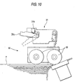
- a sheet-feed-pressure varying mechanism shown in Fig. 10 may be used for setting the start position of the working bin 78.
- the sheet-feed-pressure varying mechanism 31 is provided for the sheet feed mechanism 30 of the stencil printing machine 1 and fitted with a lever 31a for varying the sheet feed pressure in accordance with the thickness of the printing sheet P mounted on the sheet feed tray 28, and a microswitch 31b which is turned on and off as the lever 31a is turned.
- the lever 31a is situated (as shown by a solid line of Fig. 10) so as to turn off the microswitch 31b when the printing sheets P mounted on the sheet feed tray 28 are 'standard' in thickness.
- the lever 31a is also situated (as shown by a chain line of Fig. 10) so as to turn on the microswitch 31b when the printing sheets P mounted on the sheet feed tray 28 are 'thick.'
- information about the thickness of the printing sheets P is obtainable.
- the control means 170 sets the start position of the working bin 78 on the basis of the information concerning the thickness of the printing paper.
- the start position of the working bin 78 is set to the position b1 of the uppermost bin 78A
- the start position of the working bin 78 is set to the position b2 of the fifth bin lower than the uppermost bin 78A, for example.
- control of the start position of the working bin 78 is assumed on the basis of information on only the thickness of printing paper according to the aforesaid embodiments of the invention, the control thereof may be effected on the basis of information on the density of printing paper (mass per unit area). In this case, the greater the density of printing paper, the lower the start position of the working bin 78 is set than the uppermost bin 78A, whereby the indexer 116 is so controlled as to move with the set start position of the working bin 78 as a starting point. Further, the information for use in determining the start position of the working bin 78 may be information deriving from a combination of thickness and density of printing paper.
- a stencil printing machine is used for an image forming machine of the image forming apparatus of the invention.
- various image forming machines such as a copying machine, a printer and the like, may be used in the image forming apparatus of the present invention.
- printed sheets can be conveyed stably to and accommodated in the target bin, irrespective of the thickness of printing paper and the like, since the start position of the working bin is set according to the thickness and density of printed paper. Therefore, the paper jam percentage in the travel route of the printed sheet is reducible, which prevents not only printing sheet from being wasted but also the printing operation from being interrupted.
Landscapes
- Collation Of Sheets And Webs (AREA)
- Pile Receivers (AREA)
Description
- The present invention relates to a sheet post-processing unit such as a sorter for distributing and accommodating printed sheets discharged from the image forming machine, and to an image forming apparatus having the sheet post processing unit and an image forming machine such as a copying machine, a printer and the like for forming images on a printing sheet.
- Various types of sheet post-processing units for distributing printed sheets which have images formed thereon and discharged from a stencil printing machine have heretofore been developed and put to practical use. Sheet post-processing units of the sorts mentioned above are desired to be devised so that while every possible effort is made for size reduction, a larger number of printed sheet of, for instance papers may be distributable.
- In such a sheet post-processing unit of a fixed bin type, a plurality of bins are fixedly arranged in the vertical direction of a casing and conveyer units fitted with fans and blowers are installed in the vertical direction of the plurality of bins and besides indexers as sheet guide means for carrying printed sheets into the corresponding bins are moved up and down vertically along travel routes of the conveyer units. Therefore, an attempt has been made to reduce the size of the whole apparatus by decreasing the dimension thereof in the depth direction. With respect to the conveyer unit, moreover, the diameter of a corner portion at both ends of a belt has also been designed for its size to be minimized. However, the following problems still exist because various types of sheet are used as printing sheet in the stencil printing machine cooperating with aforementioned sheet post-processing unit.
- When it is attempted to use the belt for conveying the printed sheet discharged from the stencil printing by means of the sheet post-processing unit thus arranged while the printed sheet is being drawn to the belt, the travel route is largely curved in the corner portion of a
belt 94a in abelt conveyer unit 94 as shown in Fig. 11. - More specifically, no problem will particularly be caused even though the
uppermost bin 78A is first used for accommodating the printed sheet in a case where the printed sheet discharged from the stencil printing machine and conveyed thereto is ordinary paper. Nevertheless, the firm thick printed paper tends to easily peel off thebelt 94a after it has made a U-turn in the corner portion of thebelt 94a and passed thereon and it also becomes readily afloat and deviates from the travel route even when asuction unit 96 is employed for drawing the printed paper to the belt. Consequently, the printed paper is conveyed at an acute angle with respect to anindexer 116 as shown by an arrow A of Fig. 11 and caused to strike against the surface of theindexer 116 in a manner sticking therein. Therefore, the printed paper becomes unaccommodated in atarget bin 78, which also poses a problem causing a paper jam. - Document JP 08169628A discloses a control device for controlling the paper sheet conveying speed of a sorter according to the preamble of
claim 1. The control device comprises an intermediate conveyance device for conveying printed paper sheets to respective bins of a sorter at a specified speed. Furthermore, the control device contains paper sheet size detecting sensors for detecting paper sheet sizes, and a paper sheet kind setting means for setting the thickness of paper sheets and paper sheet kinds such as the quality of paper. The control device controls the conveyance speed of the paper sheets on the basis of respective signals from the paper sheet size detecting sensors and paper sheet kind setting means so as to avoid paper jamming. - Document US 3937459 discloses a sorting apparatus having a vertically adjustable sheet receiving and feeding vacuum chamber and a traveling belt mechanism which directs successive sheets to a receiver, which in turn comprises a vacuum chamber and a traveling belt conveyor mechanism for transporting sheets to or past vertically spaced trays. Fingers are shiftable to and from positions to deflect sheets from the transport conveyor and cause sheets to enter the trays.
- In view of the foregoing problems, an object of the present invention is to provide an image forming apparatus capable of stably conveying printed sheet which tends to deviate from its travel route, and reducing a paper jam percentage.
- To solve the above-mentioned problems, a sorter as defined in
claim 1 is provided. - According to the present invention, the start position of the working bin is variably controlled according to the information on the thickness of printing sheet such as a printing paper and the like, whereby the printed paper trying to deviate from the travel route can be conveyed stably to the target bin and a paper jam percentage is thus reducible.
-
- Fig. 1 shows an overall block diagram of an image forming apparatus according to the present invention;
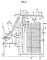
- Fig. 2 is an enlarged view of a sorter in the image forming apparatus of the present invention;
- Fig. 3 is a partial enlarged view of a bin guide conveyer unit and an indexer in the image forming apparatus of the present invention;
- Fig. 4 is a sectional view taken on line I - I of Fig. 3;
- Fig. 5 is a plan view of a matching mechanism in the image forming apparatus of the present invention;
- Fig. 6 is a diagram illustrating an operating panel which is installed in a stencil printing machine of the image forming apparatus of the invention;
- Figs. 7(a) and 7(b) are diagrams showing examples of display screens when different types of printing sheet are set in the image forming apparatus of the invention;
- Fig. 8 is a block diagram illustrating an electrical arrangement in the image forming apparatus according to the invention;
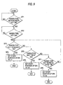
- Fig. 9 is a flowchart showing a method of setting the start position of the working bin in the image forming apparatus of the invention;
- Fig. 10 is a block diagram of a sheet feed mechanism, in place of the operating panel, for setting different kinds of printing sheet in the image forming apparatus of the invention; and
- Fig. 11 is a diagram illustrating an ideal and an abnormal state in which printed paper is conveyed.
-
- Fig. 1 is an overall block diagram of an image forming apparatus according to the present invention. In this embodiment, the image forming apparatus comprises a
stencil printing machine 1 as an image forming machine and asorter 2 as a sheet post-processing unit. - A description will be given of the construction of the
stencil printing machine 1 first. Thestencil printing machine 1 has acylindrical drum 4 rotatably supported with a machine frame (not shown) round the center axis of thecylindrical drum 4. Thecylindrical drum 4 is porous in structure and has aclamp mechanism 6 on its outer peripheral portion. Theclamp mechanism 6 retains one end of astencil 8. - The
cylindrical drum 4 is coupled to and driven by asprocket 10 installed in a manner coaxial with thecenter axis 4a. Anendless belt 12 is used for coupling thesprocket 10 to the drivingsprocket 11 cf thedrum driving motor 14a of adrum driving mechanism 14. The motive power of thedrum driving motor 14a of thedrum driving mechanism 14 works to drive thecylindrical drum 4 to rotate counterclockwise intermittently or continuously. - A printing ink supply means 16 is provided in the body of the
cylindrical drum 4. The printing ink supply means 16 is disposed so that its outer peripheral face is brought into contact with the inner peripheral face of thecylindrical drum 4. The printing ink supply means 16 has asqueegee roller 20 capable of rotation round thecenter axis 18 of the printing ink supply means 16, and adoctor roller 22 extending along the direction of the generating line of thesqueegee roller 20 with a predetermined space left with respect to the outer peripheral face of thesqueegee roller 20. The printing ink supply means 16 is used for supplying printing ink in anink reservoir 24 onto the inner peripheral face of thecylindrical drum 4 when thesqueegee roller 20 is driven to rotate synchronously in the same direction in which thecylindrical drum 4 rotates. - The printing ink in the
ink reservoir 24 is passed through the space between thesqueegee roller 20 and thedoctor roller 22 as thesqueegee roller 20 rotates, when the ink is metered so that a printing ink layer uniform in thickness may be formed on the outer peripheral face of thesqueegee roller 20. The printing ink layer is applied to the inner peripheral face of thecylindrical drum 4 for printing purposes as thesqueegee roller 20 rotates. Apress roller 26 for pressing a printing sheet P against thecylindrical drum 4 installed opposite to thesqueegee roller 20 is positioned outside thecylindrical drum 4. - A sheet feed tray 28 for setting the printing sheet P, such as a paper, to be fed between the
cylindrical drum 4 and thepress roller 26 is installed in a left-hand diagonally-downward position. Thesheet feed tray 28 is moved up and down by a driving unit (not shown) in proportion to the quantity of stacked the printing sheets P thus set thereon. - A
sheet feed mechanism 30 is positioned in the proximity of thesheet feed tray 28. Thesheet feed mechanism 30 has asheet feed roller 32 made of, for example, rubber and a pair oftiming rollers 34. Thesheet feed roller 32 picks up the uppermost sheet P to be printed out of those stacked on thepaper feed tray 28 one by one and conveys that printing sheet P toward thetiming roller side 34. While temporarily holding the printing sheet P conveyed from thesheet feed roller 32 in such a state as to form a predetermined roller-to-roller loop, thetiming rollers 34 rotate at predetermined timing in synchronization with the rotation of thecylindrical drum 4 in order to convey the printing sheet P toward thecylindrical drum 4 when the printing operation is performed. - A
stencil discharge mechanism 48 is provided round thecylindrical drum 4 and above thesheet feed tray 28. Thestencil discharge mechanism 48 is used for peeling off the used stencil sheet wound on the outer peripheral face of thecylindrical drum 4 as thecylindrical drum 4 rotates and for accommodating the stencil sheets discharged. A printedsheet separating pawl 50 is provided round thecylindrical drum 4 and in a position opposite to thesheet feed mechanism 30. - The printed
sheet separating pawl 50 is used for removing the printed sheet P subjected to printing from thecylindrical drum 4. The printed sheet P peeled off by the printedsheet separating pawl 50 is conveyed by asheet discharge unit 52 toward asheet discharge port 54. Thesheet discharge unit 52 has abelt conveyer unit 56 and asuction unit 58; while the printed sheet P peeled by the printedsheet separating pawl 50 off thecylindrical drum 4 is being air-drawn by thesuction unit 58, it is conveyed by thebelt conveyer unit 56 toward thesheet discharge port 54. - A
sheet discharge tray 60 as a stacker unit is installed in the rear of thesheet discharge port 54. In a selected non-sort mode, which will be described later, thesheet discharge tray 60 accommodates the printed sheet P conveyed from thesheet discharge unit 52. Astencil storage unit 62, which is installed above thesheet discharge unit 52, stores the continuous sheet-like stencil 8 wound in the form of a roll. - A making
mechanism 64 is installed between thestencil storage unit 62 and thecylindrical drum 4. Themaking mechanism 64 has athermal head 66 and aplaten roller 68 which is positioned opposite thereto. Themaking mechanism 64 thermally making the printing stencil supplied from thestencil storage unit 62. - The
thermal head 66, though not shown in Fig. 1, has a plurality of heating elements arranged in a line, that is, at fixed intervals in the main scanning direction. The heating elements of thethermal head 66 are arranged so that they selectively generate heat in response to the image information signal read by a read unit (not shown). The printing stencil made up by the makingmechanism 64 is conveyed by astencil conveyer roller 70 toward thecylindrical drum 4. There is also installed acutter unit 72 between the makingmechanism 64 and thecylindrical drum 4, thecutter unit 72 being used to cut thestencil 8 at a point of time the printing stencil has been wound on the outer peripheral face of thecylindrical drum 4 to a desired extent. - A description will subsequently be given of the
sorter 2. Thesorter 2 has abin train 76 for accommodating the printed sheets P conveyed from thestencil printing machine 1 in acasing 74 as an outer casing. Thesorter 2 is arranged so that its multi-stage connection to thestencil printing machine 1 is made possible. In the example shown in Fig. 1, twosorters 2, namely, a preceding-stagefirst sorter 2A and a following-stagesecond sorter 2B, are coupled to thestencil printing machine 1. - The first and
second sorters first sorter 2A has anapproach conveyer mechanism 80, which will be described later. A detailed description will thereupon be given of the construction of only thefirst sorter 2A by reference of Fig. 2. - The
bin train 76 has a plurality ofbins 78 which are each formed with similar rectangular plate members. Thesebins 78 are arranged in layers at predetermined intervals d in the height direction (vertical direction) of thecasing 74 and fixed to the rear part of thecasing 74 inside. - The
approach conveyer mechanism 80 as a first conveyer means for introducing and conveying the printed sheet P from thestencil printing machine 1 into thecasing 74 is provided on one side of thecasing 74, which side is facing thepaper discharge port 54 of thestencil printing machine 1. Theapproach conveyer mechanism 80 has two belt conveyer units: a preceding-stagebelt conveyer unit 82 and a following-stagebelt conveyer unit 86. - The
belt conveyer units suction units 88 in the form of blowers are provided for the respectivebelt conveyer units - While air-drawing the printed sheet P discharged from the
paper discharge port 54 of thestencil printing machine 1 by means of thesuction units 88, the preceding-stagebelt conveyer unit 82 takes in and conveys the printed sheet P to the following-stagebelt conveyer unit 86. While air-drawing the printed sheet P taken in from the preceding-stagebelt conveyer unit 82 by means of thesuction units 88, the following-stagebelt conveyer unit 86 conveys the printed sheet P diagonally upward up to apaper introducing port 84 in the upper end portion of one side of thecasing 74. - A bin
guide conveyer mechanism 92 as a second conveyer means is provided along the height direction (vertical direction) of thecasing 74 under thepaper introducing port 84 in thecasing 74. Similar to theapproach conveyer mechanism 80, the binguide conveyer mechanism 92 has abelt conveyer unit 94 andsuction units 96 and driven by a driving means such as a DC motor. While air-drawing the printed sheet P conveyed from the following-stagebelt conveyer unit 86 up to thesheet introducing port 84 by means of thesuction units 96, the binguide conveyer mechanism 92 causes thebelt conveyer unit 94 to have the printed sheet P make a U-turn in its curved corner portion and then conveys the printed sheet P downward in the vertical direction of thebin train 76. - Fig. 3 is a partial enlarged sectional view of the bin
guide conveyer unit 92 and theindexer 116, which will be described later, as viewed from the upward; and Fig. 4 is a sectional view taken on line I - I of Fig. 3. A comb-like steppedportion 100 is formed in the surface of aframe 98 forming the base of the binguide conveyer unit 92, so that the printed sheet P is conveyed on the surface thereof. In the steppedportion 100, through-holes 93 for drawing the printed sheet P are formed at predetermined intervals. Anendless conveyer belt 94a in thebelt conveyer unit 94 is provided for each protrusion 100a of the stepped portion 100 (actually in three places in this embodiment shown). - Through-
holes 101 are formed in theendless conveyer belt 94a in positions opposite to the respective through-holes 93 of the protrusion 100a. The air-suction force of thesuction unit 96 works to air-draw the printed sheet P via the through-holes conveyer belt 94a and the printed sheet P is conveyed in such a state that it is kept sticking to the surface of theconveyer belt 94a. - A
fan 97 as a blower for pressing the printed sheet P conveyed from theapproach conveyer mechanism 80 against the surface of the belt and for sticking the printed sheet P thereon is installed in the proximity of the outer periphery of the top portion of thebelt conveyer unit 94. - A sorter
passage conveyer mechanism 102 for conveying the printed sheet P to thesecond sorter 2B connected to the preceding stage is installed above thebin train 76. Similar to theapproach conveyer mechanism 80 and the binguide conveyer mechanism 92, the sorterpassage conveyer mechanism 102 has abelt conveyer unit 104 and asuction unit 106 and driven by, for example, a DC motor as a driving means. - While air-drawing the printed sheet P conveyed by the following-stage
belt conveyer unit 86 up to thesheet introducing port 84 by means of thesuction units 106, the sorterpassage conveyer mechanism 102 discharges the printed sheet P from asheet discharge port 108 in the upper end portion of the other side face of thecasing 74 by means of thebelt conveyer unit 104 and conveys the printed sheet P up to thesheet introducing port 84 of thesecond sorter 2B. Incidentally, the sorterpassage conveyer mechanism 102 is unnecessary when only onesorter 2 is connected to thestencil printing machine 1. - A
sheet passage sensor 109 is installed on the exit side of thebelt conveyer unit 104 in the sorterpassage conveyer mechanism 102. Thesheet passage sensor 109 detects the presence or absence of the passage of the printed sheet P conveyed on thebelt conveyer unit 104 before being introduced into thepaper introducing port 84 of thesecond sorter 2B from thepaper discharge port 108. - A
sorter switching plate 110 is installed in the proximity of thesheet introducing port 84 on the entrance side of the sorterpassage conveyer mechanism 102. Asorter switching sensor 112 is installed in the proximity of thesheet introducing port 84 on the entrance side of thesorter switching plate 110. Thesorter switching sensor 112 is used for detecting the printed sheet P introduced into thepaper introducing port 84 from theapproach conveyer mechanism 80 and conveyed therethrough. - The
sorter switching plate 110 is switched under the control of asolenoid 114 which is turned on and off in conformity with not only the number of printed sheet P conveyed to the preceding-stagefirst sorter 2A connected to thestencil printing machine 1 but also the set mode. In this case, thesorter switching plate 110, thesorter switching sensor 112 and thesolenoid 114 constitute asorter switching mechanism 115. - In the space between the
bin train 76 and the binguide conveyer mechanism 92 lies theindexer 116 for causing the printed sheet P to be inserted in thepredetermined bin 78 of thebin train 76. As shown in Figs. 3 - 4, theindexer 116 has arectangular support portion 116a substantially equal in width to thebin 78 and remains on standby in the home position HP1 set in a position slightly above the uppermost bin 78 (78A) initially. Anindexer HP sensor 118 for detecting the presence or absence of theindexer 116 is installed in the home position HP1. - Plate-
like guide members 120 incorporated in the surface of thesupport portion 116a of theindexer 116 are formed at predetermined intervals in the width direction of thesupport portion 116a. In the example of Fig. 3, four sets ofguide members 120 with two of them as a pair are provided. Theguide members 120 are uprightly provided in a position corresponding to therecess 100b of theframe 98 of the binguide conveyer unit 92. The surface of theguide member 120 forms aguide plane 120a curving downward from the leading end close to the binguide conveyer unit 92 up to the trailing end thereof. Further, the leading end portion of theguide member 120 is situated within arecess 100b of the steppedportion 100. - The
indexer 116 is such that both ends of itssupport member 116a are connected via a drivingbelt 122 to a driving means such as a DC servo motor. A columnar through-hole 116b is formed in a substantially central position of thesupport member 116a of theindexer 116. Anindexer sensor 124 formed with a transmission type photosensor is installed in upper and lower positions in the vertical direction of thecasing 74 in a manner holding the through-hole 116b therebetween. Theindexer sensor 124 is used for detecting the printed sheet P passed on theguide plane 120a of theindexer 116, monitoring the situation in which printed paper is unarriving or stagnant on theguide plane 120a of theindexer 116 and also detecting a jam error. In this case, theindexer 116, the drivingbelt 122 and theindexer sensors 124 constitute anindexer elevating mechanism 125. Incidentally, theindexer sensor 124 may be replaced with a photo-interrupter, which is provided for theindexer 116 and used for detecting the sheet paper P passed on theguide plane 120a of theindexer 116. - When the
indexer 116 is driven by the DC servo motor as the driving means via the drivingbelt 122, the tip of the printed sheet P conveyed by the binguide conveyer unit 92 is peeled off theconveyer belt 94a with the tips of theguide members 120, whereby the printed sheet P is received on theguide plane 120a. When theindexer sensor 124 detects that the printed sheet P has been accommodated in thebin train 76 for certain, theindexer 116 is made to move by the bin-to-bin 78 pitch with the home position HP1 as a reference position. The printed sheet P is thus inserted in each correspondingbin 78 of thebin train 76 one by one. - A switching
plate 126 is installed on the entrance side of the preceding-stagebelt conveyer unit 82 in theapproach conveyer mechanism 80. The switchingplate 126 is so controlled as to be switched when asolenoid 128 is turned on or off in according with the set mode. More specifically, the switchingplate 126 is switched so that the printed sheet P is conveyed to thesheet discharge tray 60 of thestencil printing machine 1 when the non-sort mode has been set. On the other hand, the switchingplate 126 is switched so that the printed sheet P is conveyed to thefirst sorter 2A when the mode of using thesecond sorter 2B has been set. In this case, the switchingplate 126 and thesolenoid 128 constitute aswitching mechanism 129. - A
sheet member 130 which is wound in the form of a roll is installed in a position right above the introduction end side of theuppermost bin 78A. One end of thesheet member 130 is fixedly secured to thecasing 74 and the other end of thesheet member 130 as an open end is fastened to theindexer 116. Thesheet member 130 operates to pay out and wind up the sheet, which operation is interlocked with the upward and downward movements of theindexer 116 and also prevents rebounding due to thesub-scan matching board 140 of amatching mechanism 136, which will be described later, when the printed sheet P is accommodated in thebin 78. Incidentally, the bin-side surface of thesheet member 130 is made a reference matching plane Y0 in the sub-scan direction when the sub-scan direction of the printed sheet P inserted in thebin 78 is matched. - In each of the
bins 78 constituting thebin train 76, cutportions indexer 116 is conveyed and the direction (main scan direction) perpendicular to the direction in which the printed sheet P is conveyed, respectively. Further, amatching mechanism 136 for matching the printed sheet P inserted in thebin 78 with predetermined reference matching faces is provided in the positions corresponding to thecut portions - Fig. 5 is a plan view of the
matching mechanism 136. The reference matching planes X0, Y0 are set at the left lower corner of Fig. 5. More specifically, the reference matching plane Y0 in the sub-scan direction is set on the bin-side surface of thesheet member 130 as described above, whereas the reference matching plane X0 in the main scan direction is set on the inner wall surface of a cover member which can be opened and closed with respect to thecasing 74, so that the cover member is made openable when the printed sheet P in thebin 78 is taken out. - The
matching mechanism 136 has a mainscan matching plate 138 which is moved in the main scan direction within thecut portion 132 extending in a direction perpendicular to the direction in which the printed sheet P is conveyed, and asub-scan matching plate 140 which is moved in the sub-scan direction within thecut portion 132 extending therein. - The outermost position of the
cut portion 132 is set to a main scan home position HP2 as a stand-by reference position when the main scan matching plate is moved. A mainscan HP sensor 142 is installed in the proximity of the outermost position of thecut portion 132, for detecting whether or not the mainscan matching plate 138 is positioned at the main scan home position HP2. - Similarly, the outermost position of the
cut portion 134 is set to a sub-scan home position HP3 as a stand-by reference position when the sub-scan matching plate is moved. Asub-scan HP sensor 144 for detecting whether or not thesub-scan matching plate 140 is provided at the sub-scan home position HP3 is installed in the proximity of the outermost position of thecut portion 134. The mainscan matching plate 138 and thesub-scan matching plate 140 are connected to, for example,pulse motors - In other words, the main
scan matching plate 138 is moved in the main scan direction by the pulse quantity with the main scan home position HP2 as a reference when the pulse quantity of the pulse motor as the driving means is determined according to preset sheet main-scan data in conformity with the size of printing sheet. Moreover, thesub-scan matching plate 140 is moved in the sub-scan direction by the pulse quantity with the sub-scan home position HP3 as a reference when the pulse quantity of the pulse motor as the driving means is determined according to preset sheet sub-scan data in conformity with the size of printing sheet. - Thus, the main
scan matching plate 138 and thesub-scan matching plate 140 are moved in conformity with the size of the printing sheet, whereby the printed sheet P inserted in eachbin 78 of the bin train 76 from theindexer 116 is matched with the reference matching planes X0, Y0. - The size of printed sheet that can be accommodated in each bin 78 is restricted by the positional relation between the two matching
plates HP sensors plates bin 78 becomes what is defined by moving the two matchingplates plates bin 78 becomes what allows the printed sheet to be accommodated therein without its interference with eitherHP sensor - The
stencil printing machine 1 and thesorter 2 thus arranged are connected together by mounting theapproach conveyer mechanism 80 on thepaper discharge port 54 of thestencil printing machine 1. The operation of distributing and accommodating printing sheets in thebin train 76 of thesorter 2 is performed through pressing specific keys provided on theoperating panel 146 of thestencil printing machine 1 as will be described below. - Fig. 6 shows an operating panel mounted on a stencil printing machine. The
operating panel 146 is provided with a tenkey pad 148, a number-of-sheets LED 150, adisplay 158 such as a liquid crystal panel, a paper-typesetting mode key 159, asort mode key 160, amode LED 162, astart key 164 and astop key 166. - The ten
key pad 148 includes number keys 0 - 9, which are used for setting the number of printing sheets and dimensions in the main scanning and sub-scanning directions of free size in a user mode. - The number-of-
sheets LED 150 displays the number of sheets set through the tenkey pad 148. The value displayed by the number-of-sheets LED 150 is decremented by one each time the printed sheet P is discharged synchronously during the printing operation performed by thestencil printing machine 1. - When the paper-type
setting mode key 159 is pressed, thedisplay 158 displays a paper-type inputting screen in order to determine the start position of the workingbin 78. More specifically, an input display screen for displaying a paper-type setting key 158a as a software key shown in Fig. 7(a) appears instead through the operation of the paper-typesetting mode key 159. When the paper-type setting key 158a is depressed, the screen is switched over to what displayskeys display 158 displays an error indication when an error such as a jam occurs, the size of printing sheet P detected by thesheet feed mechanism 30 and the like. - The paper-type
setting mode key 159 is pressed in case that a mode for changing the start position of the workingbin 78 in accordance with the thickness of printing paper P to be used in thestencil printing machine 1 is to be selected. - The
sort mode key 160 is pressed when one of the following modes is selected: a non-sort mode in which the printed sheet P is accommodated by using thesheet discharge tray 60, one of the three modes (a sort mode, a group mode and a continuous mode) in which the printed sheet P is accommodated by using thesorter 2. Thesort mode key 160 is used for sequentially switching the following modes each time it is pressed after the operating panel is supplied with power: namely, from non-sort mode to sort mode, group mode, continuous mode and non-sort mode in a loop. - The non-sort mode refers to a mode in which the printed sheet P discharged from the
paper discharge port 54 of thestencil printing machine 1 is directly discharged onto thesheet discharge tray 60. - The sort mode refers to a mode in which the printed sheet P discharged from the
paper discharge port 54 of thestencil printing machine 1 are page-to-page accommodated in thebins 78 in order to gather the plurality of pages into printed matter. - The group mode refers to a mode in which the printed sheets P discharged from the
sheet discharge port 54 of thestencil printing machine 1 are sorted into groups on a manuscript basis before being accommodated in thebins 78, which makes it possible to sort the printed papers into combinations of 'number of sheets x number of sets' on that manuscript basis. - The continuous mode refers to a mode in which the printed sheets P discharged from the
sheet discharge port 54 of thestencil printing machine 1 are distributed to and accommodated in each bin 78 by one sheet at a time so as to reduce the back printing of printed matter. - The
mode LED 162 displays the mode (the sort mode, the group mode or the continuous mode) selected by thesort mode key 160. In a case where themode LED 162 displays nothing, the non-sort mode has been selected. - The
start key 164 is pressed when the operation of thestencil printing machine 1 and thesorter 2 is to be performed. Thestop key 166 is pressed when the operation of thestencil printing machine 1 and thesorter 2 is to be stopped. - Fig. 8 is a block diagram illustrating an electrical arrangement of the aforesaid image forming apparatus. In Fig. 8, a control means (CPU) 170 such as a microprocessor is used for controlling each of the mechanisms in the apparatus according to the program stored in a
ROM 172. - A
RAM 174 for storing information fed from theoperating panel 146 is connected to the control means 170, the information including the number of printing, free size at the time the user mode is set, various sort modes and the like. - The control means 170 is used for controlling the rotation of the
cylindrical drum 4 by issuing a rotation command to thedrum driving mechanism 14. The control means 170 also issues to the making mechanism 64 a command of making up thestencil 8, to the clamp mechanism 6 a command of retaining/releasing thestencil 8 by/from thecylindrical drum 4, to the stencil discharge mechanism 48 a command of peeling the usedstencil 8 off thecylindrical drum 4, and to the sheet feed mechanism 30 a command of performing the operation of feeding the printing sheet P, which operation is interlocked with thedrum driving mechanism 14. - As shown in Fig. 8, a
control unit 176 for controlling the operation of each mechanism of thesorter 2 is provided on the sorter side. Thiscontrol unit 176 and the control means 170 of thestencil printing machine 1 are electrically connected via a cable or the like, so that control information is exchanged therebetween. Thecontrol unit 176 is used for synchronously controlling the operation of thesorter 2 for successively taking in the printed sheets P discharged one by one from thestencil printing machine 1 according to the control commands from the control means 170 under the control thereof. - When an error occurs on the part of-the
sorter 2, thecontrol unit 176 notifies the occurrence of such an error to the control means 170 and deals with the error according to control instructions from the control means 170. - Consequently, the
control unit 176 issues control commands to theapproach conveyer mechanism 80, the binguide conveyer mechanism 92, the sorterpassage conveyer mechanism 102, thesorter switching mechanism 115, theindexer elevating mechanism 125, theswitching mechanism 129, thematching mechanism 136 and the like in thesorter 2. - Under the command issued to each mechanism, the printed sheets P discharged from the
stencil printing machine 1 are sorted out and accommodated in the correspondingbins 78 of thesorter 2 in conformity with the set mode. - Although it has been arranged that the
operating panel 146 is installed on the stencilprinting machine side 1, a similar operating panel may be installed on thesorter side 2 so as to send set contents resulting from the operation of that operating panel to the control means 170 of thestencil printing machine 1. Moreover, the operatingpanels 146 may be installed in bothstencil printing machine 1 andsorter 2. - In the image forming system thus arranged, the start position of the working bin as shown in a flowchart of Fig. 9 prior to the distribution of the printed sheets P discharged from the
stencil printing machine 1 in conformity with the respective modes. - When the paper-type
setting mode key 159 of theoperating panel 146 is pressed first (SP1 - Yes), the mode is switched over to what is for setting the start position of the workingbin 78. Thedisplay 158 changes to an input display screen displaying the paper-type setting key 158a as shown in Fig. 7(a). When the paper-type setting key 158a is depressed (SP2 - Yes), the screen is switched over to what displays three kinds ofkeys - When the key 158b representing 'standard', with the total number of bins set to 50, for example, is depressed (SP3 - Yes), the control means 170 (or the control unit 176) sets the start position of the working
bin 78 to the uppermost position b1 (a first bin from above) (SP4) according to the output. When the key 158c representing 'thick paper' is depressed (SP5 - Yes), the control means 170 (or the control unit 176) sets the start position of the workingbin 78 to the position b2 of a fifth bin from the uppermost side (SP6) according to the output. When the key 158d representing 'especially thick paper' is depressed (SP7 - Yes), the control means 170 (or the control unit 176) sets the start position of the workingbin 78 to the position b3 of a tenth bin from the uppermost side (SP8) according to the output. - When the setting of the start position of the working
bin 78 is completed in accordance with the thickness of printing paper P for use in thestencil printing machine 1, the sort printing operation is made performable hereafter. Then themode switching plate 126 is switched over to the sorter side and so is thesorter switching plate 110 to the bin guideconveyer unit side 86, whereby the printed paper P discharged from thestencil printing machine 1 is conveyed via theapproach conveyer mechanism 80 up to the binguide conveyer unit 86. - When the printed sheet P is guided and conveyed by the bin
guide conveyer unit 86 up to theindexer 116, theindexer 116 is moved by the bin-to-bin 78 pitch with the home position HP1 as a reference position. Thus the printed sheet P is inserted in each correspondingbin 78 one by one. - While the start position of the working
bin 78 in accordance with the thickness of the printed sheet P is set through the operation of theoperating panel 146, theindexer 116 is so controlled by thecontrol unit 176 as to move up to the start position of the workingbin 78 with the home position HP1 as the reference and to move by the bin-to-bin 78 pitch with the start position as a starting point. In other words, with the thickness of the paper being 'standard,' the start position b1 set by depressing the paper-type key 158b becomes the starting point of theindexer 116. With the thickness of the paper being 'thick,' the start position b2 set by depressing the paper-type key 158c becomes the starting point of theindexer 116. With the thickness of the paper being 'especially thick,' the start position b3 set by depressing the paper-type key 158d becomes the starting point of theindexer 116. - When printing paper for use in the
stencil printing machine 1 is thick or especially thick, the start position of the workingbin 78 is thus set to the position b2 or b3, which is lower by the predetermined number of bins than the standard. When the thick or especially thick printing paper P is conveyed from thesheet introducing port 84 to the binguide conveyer mechanism 92, theindexer 116 is so controlled as to move to the position lower by the predetermined steps than theuppermost bins 78A; that is, up to the position b2 or b3 set in conformity with the thickness of printing paper P for use in thestencil printing machine 1. - Therefore, even though the printed sheet P deviates from the travel route when it makes a U-turn in the curved corner portion of the bin
guide conveyer mechanism 92 and passes thereon, it is drawn by thesuction unit 96 of the binguide conveyer mechanism 92 and returns to the travel route. Consequently, the printed sheet P is inserted in thetarget bin 78 via theguide member 120 of theindexer 116 as shown by an arrow B of Fig. 11 without being delivered to theindexer 116 at an acute angle as shown by the arrow B thereof. - Unless the start position of the working
bin 78 is especially set, theindexer 116 is so controlled as to move by the bin-to-bin 78 pitch with the home position HP1 as the reference position in a manner making thesurface 78d of thebin 78 correspond to thesurface 116c of the downstream-side end portion of theindexer 116. - The
indexer 116 in thesorter 2 is moved to a desiredbin 78 in conformity with the mode (the sort mode, the group mode or the continuous mode) selected by thesort mode key 160. - Then the
second sorter 2B is installed as an additional one of thefirst sorter 2A in order to basically sort out more printed sheets P. The printed papers P are conveyed to thesecond sorter 2B by switching thesorter switching plate 110 of thefirst sorter 2A over to the sorter passage conveyer unit side, whereby the printed sheet P is conveyed via the sorterpassage conveyer unit 102 to the following-statesecond sorter 2B before being inserted in the correspondingbin 78 as in thefirst sorter 2A. - Thus, the printed paper P is inserted in the sorter 2 (2A or 2B) in accordance with the mode (the sort mode, the group mode or the continuous mode) selected by the
sort mode key 160. - In this embodiment, the
operating panel 146 is used to set one type of printing paper to determine the start position of the workingbin 78, the different types of printing paper in terms of their thickness are not limited to 'standard', 'thick paper' and 'especially thick paper' but may include other kinds of thickness to be allocated. At this time, it is unnecessary to allocate a key to each kind of thickness and provided a combination of keys can be set, a smaller number of keys may be used for setting more kinds of thickness. A sheet-feed-pressure varying mechanism shown in Fig. 10 may be used for setting the start position of the workingbin 78. - The sheet-feed-
pressure varying mechanism 31 is provided for thesheet feed mechanism 30 of thestencil printing machine 1 and fitted with alever 31a for varying the sheet feed pressure in accordance with the thickness of the printing sheet P mounted on thesheet feed tray 28, and amicroswitch 31b which is turned on and off as thelever 31a is turned. - In the sheet-feed-
pressure varying mechanism 31, thelever 31a is situated (as shown by a solid line of Fig. 10) so as to turn off themicroswitch 31b when the printing sheets P mounted on thesheet feed tray 28 are 'standard' in thickness. Thelever 31a is also situated (as shown by a chain line of Fig. 10) so as to turn on themicroswitch 31b when the printing sheets P mounted on thesheet feed tray 28 are 'thick.' Thus, information about the thickness of the printing sheets P is obtainable. - The control means 170 (or the control unit 176) sets the start position of the working
bin 78 on the basis of the information concerning the thickness of the printing paper. When themicroswitch 31b is held OFF, for example, the start position of the workingbin 78 is set to the position b1 of theuppermost bin 78A, whereas when themicroswitch 31b is held ON, with the total number ofbins 78 being 50, the start position of the workingbin 78 is set to the position b2 of the fifth bin lower than theuppermost bin 78A, for example. - Although the control of the start position of the working
bin 78 is assumed on the basis of information on only the thickness of printing paper according to the aforesaid embodiments of the invention, the control thereof may be effected on the basis of information on the density of printing paper (mass per unit area). In this case, the greater the density of printing paper, the lower the start position of the workingbin 78 is set than theuppermost bin 78A, whereby theindexer 116 is so controlled as to move with the set start position of the workingbin 78 as a starting point. Further, the information for use in determining the start position of the workingbin 78 may be information deriving from a combination of thickness and density of printing paper. - In this embodiment, a stencil printing machine is used for an image forming machine of the image forming apparatus of the invention. However, various image forming machines, such as a copying machine, a printer and the like, may be used in the image forming apparatus of the present invention.
- As is obvious from the description given above, printed sheets can be conveyed stably to and accommodated in the target bin, irrespective of the thickness of printing paper and the like, since the start position of the working bin is set according to the thickness and density of printed paper. Therefore, the paper jam percentage in the travel route of the printed sheet is reducible, which prevents not only printing sheet from being wasted but also the printing operation from being interrupted.
Claims (4)
- A sorter for sorting a printed sheet discharged from an image forming machine, the sorter comprising:characterized in thata plurality of bins (78) arranged in a vertical direction;conveyer means (92) provided vertically along the plurality of bins and comprising a paper introducing port (84) for bending the printed sheet to convey the printed sheet vertically downward by a belt while air-drawing the printed sheet to the belt;printed sheet guide means (116) having a guide surface in its upper portion for peeling the printed sheet off the conveyer means (92) with the guide surface and sending the printed sheet in either one of the plurality of bins;control means (170) connecting to the conveyer means (92) and the printed sheet guide means (116), for driving the conveyer means and the printed sheet guide means (116); andprinting sheet information input means (158) connecting to the control means, wherein the printing sheet information input means (158) receives a printing sheet information of the sheet to be printed and feed the information to the control means, the printing sheet information including information about a thickness and/or a density of the printed sheet,
the printed sheet guide means (116) is vertically movable along a sheet travel route of the conveyer, and
the control means is adapted to set a start position of the printed sheet guide means (116) in accordance with the printing sheet information such that the start position is lowered when the thickness and/or the density is higher than a standard value, thereby insuring adhesion of the printed sheet to the belt at the start position. - An image forming apparatus comprising a sorter according to claim 1, the image forming apparatus further comprising:image forming means for printing an image on a printing sheet; andfirst conveyer means (80) having a belt, for conveying the printed sheet discharged from the image forming means while air-drawing the printed sheet to the belt; whereinthe control means (170) is adapted to control driving of the first conveyer means, the conveyer means and the printed sheet guide means in accordance with the printed sheet discharged from the image forming means.
- The image forming apparatus according to claim 2, wherein the printing sheet information input means inputs to the control means (170) a signal which is switched on or off in accordance with a variation of pressure applied to the printing sheet supplied to the image forming means as information on the thickness of the printing sheet.
- The image forming apparatus according to claim 2, wherein the printing sheet information input means inputs to the control means a key signal which is given in accordance with the thickness and/or the density of the printing sheet as information on the thickness and/or the density of the printing sheet.
Applications Claiming Priority (3)
| Application Number | Priority Date | Filing Date | Title |
|---|---|---|---|
| JP11772696 | 1996-05-13 | ||
| JP117726/96 | 1996-05-13 | ||
| JP11772696A JP3652439B2 (en) | 1996-05-13 | 1996-05-13 | Image forming system |
Publications (3)
| Publication Number | Publication Date |
|---|---|
| EP0807595A2 EP0807595A2 (en) | 1997-11-19 |
| EP0807595A3 EP0807595A3 (en) | 1998-03-18 |
| EP0807595B1 true EP0807595B1 (en) | 2002-08-07 |
Family
ID=14718774
Family Applications (1)
| Application Number | Title | Priority Date | Filing Date |
|---|---|---|---|
| EP97107726A Expired - Lifetime EP0807595B1 (en) | 1996-05-13 | 1997-05-12 | Sorter and image forming apparatus having the same |
Country Status (4)
| Country | Link |
|---|---|
| US (1) | US5931463A (en) |
| EP (1) | EP0807595B1 (en) |
| JP (1) | JP3652439B2 (en) |
| DE (1) | DE69714508T2 (en) |
Families Citing this family (6)
| Publication number | Priority date | Publication date | Assignee | Title |
|---|---|---|---|---|
| JP2000219423A (en) * | 1999-01-29 | 2000-08-08 | Riso Kagaku Corp | Image forming system |
| JP2000218913A (en) * | 1999-01-29 | 2000-08-08 | Riso Kagaku Corp | Printing system |
| JP4483557B2 (en) * | 2004-06-23 | 2010-06-16 | コニカミノルタビジネステクノロジーズ株式会社 | Paper stacking apparatus and image forming system |
| JP2010111062A (en) * | 2008-11-07 | 2010-05-20 | Fuji Xerox Co Ltd | Image forming system and program |
| CN109080270B (en) * | 2018-09-17 | 2024-02-06 | 北京兆维电子(集团)有限责任公司 | Channel for conveying bills or papers |
| CN111675010B (en) * | 2020-06-24 | 2025-01-17 | 广东栗子科技有限公司 | Automatic film stacking machine and control method thereof |
Family Cites Families (6)
| Publication number | Priority date | Publication date | Assignee | Title |
|---|---|---|---|---|
| US3937459A (en) * | 1974-09-16 | 1976-02-10 | Keith B. Stewart | Sorting machine |
| JPS5648644A (en) * | 1979-09-28 | 1981-05-01 | Ricoh Co Ltd | Method for controlling sheet number display of document copying apparatus having collator |
| JPS5733152A (en) * | 1980-07-31 | 1982-02-23 | Olympus Optical Co Ltd | Collator |
| JPS58183563A (en) * | 1982-04-16 | 1983-10-26 | Toshiba Corp | Apparatus for sorting and receiving blank |
| CH658236A5 (en) * | 1982-10-27 | 1986-10-31 | Kurt Ruenzi | SORTING DEVICE FOR PAPER SHEET. |
| JP3343455B2 (en) * | 1994-12-14 | 2002-11-11 | 東北リコー株式会社 | Control method of paper transport speed in sorter and paper transport speed control device in sorter |
-
1996
- 1996-05-13 JP JP11772696A patent/JP3652439B2/en not_active Expired - Fee Related
-
1997
- 1997-05-12 EP EP97107726A patent/EP0807595B1/en not_active Expired - Lifetime
- 1997-05-12 DE DE69714508T patent/DE69714508T2/en not_active Expired - Fee Related
- 1997-05-13 US US08/855,611 patent/US5931463A/en not_active Expired - Lifetime
Also Published As
| Publication number | Publication date |
|---|---|
| DE69714508T2 (en) | 2002-12-05 |
| JPH09301622A (en) | 1997-11-25 |
| US5931463A (en) | 1999-08-03 |
| EP0807595A2 (en) | 1997-11-19 |
| JP3652439B2 (en) | 2005-05-25 |
| DE69714508D1 (en) | 2002-09-12 |
| EP0807595A3 (en) | 1998-03-18 |
Similar Documents
| Publication | Publication Date | Title |
|---|---|---|
| US5835839A (en) | Sorter having a controller for setting the conveying means of the sorter and image forming apparatus having the same | |
| JP3213424B2 (en) | Paper stencil sheet ejection device | |
| JPS6337069A (en) | Sheet stacker | |
| JP3236064B2 (en) | Stencil printing machine | |
| EP0807595B1 (en) | Sorter and image forming apparatus having the same | |
| JP3310107B2 (en) | Control device in image forming apparatus and sorter apparatus | |
| US6276267B1 (en) | Printing system | |
| US5890050A (en) | Sorter having a controller which adjusts for different types of paper used in an image forming apparatus | |
| JP3639381B2 (en) | Image forming apparatus | |
| JP3664805B2 (en) | Image forming system | |
| JP3464958B2 (en) | Paper discharge device, collating device using the same, and image forming apparatus | |
| JPH09301625A (en) | Image forming device | |
| JP3639380B2 (en) | Image forming apparatus | |
| JP4302388B2 (en) | Image forming apparatus | |
| JP3618565B2 (en) | Image forming system | |
| JP3708217B2 (en) | Image forming apparatus | |
| US6324360B1 (en) | Image forming system having an after-processing apparatus | |
| US20050217520A1 (en) | Image forming apparatus | |
| JPH1194U (en) | Printing equipment | |
| JPH1120293A (en) | Sheet feed device for rotary screen printing machine | |
| JPH0494367A (en) | Paper ejection device | |
| JPH1110995A (en) | Sheet feeder for rotary stencil printer | |
| JPH09315661A (en) | Sorting device for printer | |
| JP2000255879A (en) | Sheet discharge and storing device | |
| JPH07165339A (en) | Parallel paper feeding device |
Legal Events
| Date | Code | Title | Description |
|---|---|---|---|
| PUAI | Public reference made under article 153(3) epc to a published international application that has entered the european phase |
Free format text: ORIGINAL CODE: 0009012 |
|
| 17P | Request for examination filed |
Effective date: 19970512 |
|
| AK | Designated contracting states |
Kind code of ref document: A2 Designated state(s): DE FR GB |
|
| PUAL | Search report despatched |
Free format text: ORIGINAL CODE: 0009013 |
|
| AK | Designated contracting states |
Kind code of ref document: A3 Designated state(s): DE FR GB |
|
| 17Q | First examination report despatched |
Effective date: 20000620 |
|
| GRAG | Despatch of communication of intention to grant |
Free format text: ORIGINAL CODE: EPIDOS AGRA |
|
| GRAG | Despatch of communication of intention to grant |
Free format text: ORIGINAL CODE: EPIDOS AGRA |
|
| GRAH | Despatch of communication of intention to grant a patent |
Free format text: ORIGINAL CODE: EPIDOS IGRA |
|
| GRAH | Despatch of communication of intention to grant a patent |
Free format text: ORIGINAL CODE: EPIDOS IGRA |
|
| GRAA | (expected) grant |
Free format text: ORIGINAL CODE: 0009210 |
|
| AK | Designated contracting states |
Kind code of ref document: B1 Designated state(s): DE FR GB |
|
| REG | Reference to a national code |
Ref country code: GB Ref legal event code: FG4D |
|
| REF | Corresponds to: |
Ref document number: 69714508 Country of ref document: DE Date of ref document: 20020912 |
|
| ET | Fr: translation filed | ||
| PLBE | No opposition filed within time limit |
Free format text: ORIGINAL CODE: 0009261 |
|
| STAA | Information on the status of an ep patent application or granted ep patent |
Free format text: STATUS: NO OPPOSITION FILED WITHIN TIME LIMIT |
|
| 26N | No opposition filed |
Effective date: 20030508 |
|
| PGFP | Annual fee paid to national office [announced via postgrant information from national office to epo] |
Ref country code: DE Payment date: 20080515 Year of fee payment: 12 |
|
| PGFP | Annual fee paid to national office [announced via postgrant information from national office to epo] |
Ref country code: GB Payment date: 20080514 Year of fee payment: 12 |
|
| GBPC | Gb: european patent ceased through non-payment of renewal fee |
Effective date: 20090512 |
|
| REG | Reference to a national code |
Ref country code: FR Ref legal event code: ST Effective date: 20100129 |
|
| PG25 | Lapsed in a contracting state [announced via postgrant information from national office to epo] |
Ref country code: FR Free format text: LAPSE BECAUSE OF NON-PAYMENT OF DUE FEES Effective date: 20090602 |
|
| PGFP | Annual fee paid to national office [announced via postgrant information from national office to epo] |
Ref country code: FR Payment date: 20080514 Year of fee payment: 12 |
|
| PG25 | Lapsed in a contracting state [announced via postgrant information from national office to epo] |
Ref country code: GB Free format text: LAPSE BECAUSE OF NON-PAYMENT OF DUE FEES Effective date: 20090512 |
|
| PG25 | Lapsed in a contracting state [announced via postgrant information from national office to epo] |
Ref country code: DE Free format text: LAPSE BECAUSE OF NON-PAYMENT OF DUE FEES Effective date: 20091201 |