EP0807563A2 - Rollpalette - Google Patents
Rollpalette Download PDFInfo
- Publication number
- EP0807563A2 EP0807563A2 EP96307769A EP96307769A EP0807563A2 EP 0807563 A2 EP0807563 A2 EP 0807563A2 EP 96307769 A EP96307769 A EP 96307769A EP 96307769 A EP96307769 A EP 96307769A EP 0807563 A2 EP0807563 A2 EP 0807563A2
- Authority
- EP
- European Patent Office
- Prior art keywords
- lock member
- platform
- deck
- securing means
- platforms
- Prior art date
- Legal status (The legal status is an assumption and is not a legal conclusion. Google has not performed a legal analysis and makes no representation as to the accuracy of the status listed.)
- Granted
Links
- 238000006073 displacement reaction Methods 0.000 claims abstract description 17
- 229920003023 plastic Polymers 0.000 claims description 15
- 239000004033 plastic Substances 0.000 claims description 15
- 238000000465 moulding Methods 0.000 claims description 10
- 230000000295 complement effect Effects 0.000 claims description 6
- 230000000717 retained effect Effects 0.000 claims description 2
- 230000008878 coupling Effects 0.000 abstract description 32
- 238000010168 coupling process Methods 0.000 abstract description 32
- 238000005859 coupling reaction Methods 0.000 abstract description 32
- 230000004048 modification Effects 0.000 abstract description 8
- 238000012986 modification Methods 0.000 abstract description 8
- 235000004443 Ricinus communis Nutrition 0.000 description 1
- 240000000528 Ricinus communis Species 0.000 description 1
- 238000010276 construction Methods 0.000 description 1
- 230000000694 effects Effects 0.000 description 1
- 238000004519 manufacturing process Methods 0.000 description 1
- 238000005007 materials handling Methods 0.000 description 1
- 238000000034 method Methods 0.000 description 1
Images



Classifications
-
- B—PERFORMING OPERATIONS; TRANSPORTING
- B60—VEHICLES IN GENERAL
- B60D—VEHICLE CONNECTIONS
- B60D1/00—Traction couplings; Hitches; Draw-gear; Towing devices
- B60D1/48—Traction couplings; Hitches; Draw-gear; Towing devices characterised by the mounting
- B60D1/483—Traction couplings; Hitches; Draw-gear; Towing devices characterised by the mounting adapted for being mounted to the side of a vehicle
-
- B—PERFORMING OPERATIONS; TRANSPORTING
- B60—VEHICLES IN GENERAL
- B60D—VEHICLE CONNECTIONS
- B60D1/00—Traction couplings; Hitches; Draw-gear; Towing devices
-
- B—PERFORMING OPERATIONS; TRANSPORTING
- B62—LAND VEHICLES FOR TRAVELLING OTHERWISE THAN ON RAILS
- B62B—HAND-PROPELLED VEHICLES, e.g. HAND CARTS OR PERAMBULATORS; SLEDGES
- B62B5/00—Accessories or details specially adapted for hand carts
- B62B5/0083—Wheeled supports connected to the transported object
-
- B—PERFORMING OPERATIONS; TRANSPORTING
- B62—LAND VEHICLES FOR TRAVELLING OTHERWISE THAN ON RAILS
- B62B—HAND-PROPELLED VEHICLES, e.g. HAND CARTS OR PERAMBULATORS; SLEDGES
- B62B2207/00—Joining hand-propelled vehicles or sledges together
- B62B2207/02—Joining hand-propelled vehicles or sledges together rigidly
Definitions
- roller platforms sometimes called roller pallets, are well known for materials handling and conventionally comprise a deck carrying rollers such as castors or other wheels by which mobility is provided for the platform.
- the load carrying area of the deck is of a modular size to accommodate one or more articles of predetermined dimensions, such as containers. It has been proposed to provide a means whereby the decks of two similar platforms can be engaged with each other to provide an enlarged load carrying deck area and it is an object of the present invention to provide a roller platform which provides this facility in a relatively simple platform structure.
- a roller platform comprising a deck carrying roller means which provide the platform with mobility, the deck having a lock member with a longitudinally extending axis, the lock member being longitudinally displaceable relative to the deck so that when two similar said platforms are positioned adjacent to each other with their decks in a common plane, the lock member can be displaced to a position in which it bridges longitudinally both decks, and wherein securing means is provided which is engageable between the lock member and both decks to restrain the platforms from displacement relative to each other.
- the deck of the platform carries a lock member which, when not in use, will normally be retained unobtrusively on the deck and which when required for coupling together two similar platforms is displaceable longitudinally of itself to bridge the decks of the two platforms so that the securing means can be engaged between the decks of both platforms and the lock member in a sense to restrain the platforms from displacement relative to each other.
- the two lock members can bridge both decks of the two platforms and securing means engaged between the two lock members and the two platforms thereby permitting greater rigidity to be achieved between the platforms which are coupled together (as compared with when a single lock member is utilized).
- the securing means can be carried by the lock member and/or the deck.
- the securing means is carried by the lock member and may be formed integral therewith, for example by the lock member and securing means being formed as a plastics moulded unit.
- the lock member With the securing means carried by the lock member, the lock member may be rotatable about its longitudinal axis to a condition in which the securing means engages both decks.
- the securing means can be carried on the lock member to be pivotally displaceable relative to that member to a condition in which its required engagement with the two decks is achieved.
- the securing means is presented by two longitudinally spaced lugs which project laterally on the lock member so that when the lock member bridges the decks of two platforms the lugs are engageable unobtrusively with seatings on the respective decks to secure the platforms relative to each other.
- the lugs are rigid with the lock member for unified rotation therewith to engage the lugs with the respective seatings.
- a further proposal is for the lugs to be hingedly connected to the lock member for pivotal displacement relative thereto to engage the lugs with the respective seatings.
- the securing means is presented by two longitudinal end extensions located one at each longitudinal end of the lock member and pivotally displaceable relative thereto about a laterally extending axis.
- the end extensions can be engaged with seatings on the decks of the respective platforms to secure the platforms relative to each other.
- the lock member When the lock member is not in use it is preferred that it can be displaced longitudinally to a stored position in which it is unobtrusive on the deck; in the stored position the securing means may be engageable between that member and deck, for example the lugs or end extensions as aforementioned may be engaged with seatings on the deck to retain the lock member in the aforementioned unobtrusive position.
- the securing means carried by the lock member engages with seatings as aforementioned (such seatings being either on the deck which carries that lock member or on both of two adjacent decks which the lock member bridges), it is preferred that the seatings and the securing means engage in a sense to restrain the securing means in said engagement; for example the lugs or end extensions may clip on to the seatings, be a friction fit or snap engage therewith so that a positive manual effort is required to dis-engage the securing means from its unobtrusive engagement with the seatings.
- the lock member is longitudinally displacable along a longitudinally extending track on the deck and when the lock member bridges two said decks as aforementioned, it co-operates with the tracks on both decks.
- the track has a longitudinally extending cavity part and a longitudinally extending slot part which is parallel with and opens into the cavity part.
- the lock member can be in the form of a bolt which, preferably, is complementary to and longitudinally slidable in the cavity part. Lugs as aforementioned can extend laterally from the bolt to be received in the slot part along which they are longitudinally displaceable and are presented to provide a convenient means for adjusting the lock member in its track.
- the bolt is captured in the cavity part to be restrained laterally from passing through the slot part by the width of the slot part being relatively less than that of the bolt.
- the seatings as previously mentioned for the lugs are conveniently in the form of recesses which communicate with the slot part. These recesses may accommodate the lugs of the bolt by relative rotation of the bolt about its longitudinal axis in the cavity part of the track or by pivotal movement of the lugs relative to the bolt (for the bolt to be non-rotatable) so that the lugs are unobtrusive on the deck or decks when either the bolt is extended from its deck to bridge with another deck or is withdrawn into an unobtrusive stored position on the deck which carries it.
- the lock member can be carried in an upper load carrying face or an underside face of the deck. However, for ease of access and to ensure that the lock member is clear of goods which may be carried on the deck, it is preferred that the lock member is mounted for longitudinal displacement along a side edge of the deck.
- the deck is likely to have two opposed and substantially parallel side edges so that a lock member may be carried along either of the two side edges or two lock members may be provided one in each of the opposed side edges. In an arrangement where the lock member is mounted for longitudinal displacement along a side edge, such lock member may be capable of bridging between the deck of the platform on which it is carried and the deck of a second similar platform which second similar platform may be positioned at either end of the side edge on which the lock member is carried.
- the deck will be of substantially rectangular shape in plan to have a first pair of opposed and substantially parallel side edges and a second pair of opposed and substantially parallel side edges and a lock member may be provided at a side edge or edges on either or both of the first and second pairs.
- a lock member for one of the two pairs of side edges may be removed from that side edge and re-located at the other of the two pairs of side edges as may be appropriate for the desired orientation of two decks which are to be coupled together (for example if the two decks are of oblong rectangular shape in plan they may be coupled together in side-by-side or end-to-end relationship).
- the deck will be formed in plastics.
- the deck includes a track having the longitudinally extending cavity part and the relatively narrower longitudinally extending slot part as aforementioned, it is preferred (to facilitate manufacture of the deck) that the deck is formed of at least two plastics mouldings which are secured together and each of which partly defines the longitudinally extending cavity part and the longitudinally extending slot part over their longitudinal extent.
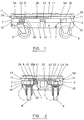
- the roller platform shown in Figures 1 to 3 has a plastics deck 1 which is of substantially oblong rectangular shape to provide a first pair of opposed parallel side edges 2 and 3, a second pair of opposed parallel side edges 4 and 5, an upper load carryingface 6 and an underface shown generally at 7.
- a plastics deck 1 which is of substantially oblong rectangular shape to provide a first pair of opposed parallel side edges 2 and 3, a second pair of opposed parallel side edges 4 and 5, an upper load carryingface 6 and an underface shown generally at 7.
- Bolted to the deck 1 on the underside face thereof are a pair of non-castoring ground engaging wheels 8 and a pair of castored wheels 9 which are located one in each of the four corners of the deck as is conventional for roller platforms.
- rectilinear tracks 4A and 5A Located in the side edges 4 and 5 are rectilinear tracks 4A and 5A respectively; these tracks 4A and 5A are substantially parallel to each other and to the upper face 6 of the deck and open at their ends into the side edges 2 and 3.
- the side edges 2 and 3 have similar rectilinear tracks 2A and 3A respectively which are substantially parallel to each other and to the upper face 6 of the deck and open at their ends into the side edges 4 and 5.
- the tracks 2A, 3A, 4A and 5A are similarly formed, each having a part cylindrical cavity 10 which extends over the length of the respective edge and a slot 11 which also extends over the length of the respective edge and opens in that edge to communicate with the cavity 10 with which it is parallel. It will be seen from Figures 1 and 2 that the tracks 2A to 5A are of substantially keyhole shape in lateral cross section whereby the width of a slot 11 is substantially less than the diameter of the cylindrical cavity 10 with which that slot communicates.
- the deck 1 is provided with two couplings 20 and 20A each of which is similar to that shown in Figures 4 to 6 and has a lock member in the form of a cylindrical bolt 21 which carries securing means in the form of a pair of coplanar lugs 22, 23 that extend radially in a similar sense from the bolt, are rigid therewith and are axially/longitudinally spaced thereon.
- the bolt 21 is complementary to the cylindrical cavity 10 of the tracks and is slidably received in such a cavity from an end of the respective track so that the lugs 22 and 23 extend through the slot 11 of the track.
- the bolt 21 can be slidably manoeuvred along, say, the track 5A until the bolt of the coupling is accommodated within the length of the side edge 5 as shown in Figure 1.
- the side edge 5 Provided in the side edge 5 are three recesses 30, 31 and 32 which are longitudinally spaced on that side edge and communicate with the slot 11 of the track 5A.
- the three recesses 30 to 32 are positioned longitudinally so that the spacing between two adjacent recesses of the three corresponds to the longitudinal spacing between the lugs 22 and 23.
- the recesses 30, 31 and 32 are complementary to the lugs 22 and 23 so that when those lugs coincide with two adjacent recesses, the coupling 20 can be rotated about the longitudinal axis of its bolt 21 by manual pressure applied to the lugs 22 and 23 to cause the lugs to move into and be accommodated by seatings provided by two adjacent recesses 30 to 32 in the side edge 5.
- the lugs 22 and 23 are shown accommodated unobtrusively in the recesses 30 and 31 respectively but it will be appreciated that they can equally be accommodated (by appropriate positioning of the lock member along the track 5A) in the recesses 31 and 32 respectively.
- the couplings 20 and 20A are shown shaded in Figures 1 and 2.
- the second coupling 20A is shown in Figure 2 accommodated by the track 2A in the side edge 2 of the deck.
- the coupling in the track 2A is substantially the same as that shown in Figure 1 but has dimensional variations to accommodate for the difference in length between the track 2A and the track 5A.
- the side edge 2 is provided with four longitudinally spaced recesses 40 to 43 which communicate with the slot 11 of the track 2A to provide seatings for the lugs 22 and 23 of the lock member 20A in the track 2A (in a similar manner to the recesses 30 to 32 for the lock member 20 in Figure 1).
- the coupling 20 is shown accommodated unobtrusively within the length of the side edge 2 with the lugs 22 and 23 received within the longitudinally spaced seatings formed by the recesses 41 and 42.
- the bolts of the couplings 20 and 20A shown in Figures 1 and 2 are restrained from longitudinal displacement in their respective tracks by location of the lugs 22 and 23 in their respective seatings provided by the recesses in the side walls.
- the lugs 22 and 23 snap engage with the seatings in which they are received. Intentional manual effort will therefore be required to engage the lug with its seating and also to dis-engage the lug from its seating.
- FIG. 9 An example of this latter arrangement is shown in Figure 9 where small ribs or other protrusions 45 are provided on the side edge 5 at longitudinally opposed positions in the mouth of the recess 32 so that the lug 22 in engaging with the seating provided by the recess 32 has to snap engage over the protrusions 45. Similar provision for snap engagement and dis-engagement between the lugs and seatings can be provided for each of the recesses 30 to 32 and 40 to 43.
- the coupling 20 in the track 5A of deck 1 can be rotated to release its lugs 22, 23 from the seatings associated with the track 5A in that deck 1 and thereafter slidably displaced as a whole along that track 5A until eventually the bolt 21 of the coupling enters into the cavity part 10 of the track 5A in the deck 1A whilst the lug 23 on the bolt is received within the slot 11 of the track 5A on the deck 1A and the bolt of the coupling 20 bridges both decks 1 and 1A as shown in Figure 7.
- the coupling 20 is rotated about the longitudinal axis of its bolt 21 so that its lugs 22 and 23 snap engage respectively with the seating 32 on the deck l and the seating 30 on the deck 1A (as shown in Figure 8).
- a coupling (not shown) carried in the track 4A of the side edge 4 on the deck 1A may be extended from that deck to bridge with the deck 1 and rotated to engage with seatings of the track 4A of the deck 1 (in a similar manner to that shown for the coupling 20 in the tracks 5A of Figure 8).
- the two decks 1 and 1A are consequently bridged by two lock members on opposite edges of the deck assembly which is formed to provide a load carrying deck face which is substantially rigid when the decks are supported on their respective rollers.
- the decks 1 and 1A of the two platforms can alternatively be coupled together in side-by-side relationship (rather than end-to-end relationship as shown in Figures 7 and 8) by use of the coupling 20A carried in the tracks 2A or 3A and that such coupling is effected in a similar manner to that previously described.
- the lug 22 will engage with a seating 43 in one deck whilst the lug 23 will engage with the seating 40 in the deck of the other platform.
- the keyhole section of the tracks 2A to 5A presents an undercut which would conventionally require a collapsible or adjustable tool for moulding the deck as a one piece component (the collapsible tool being required to permit a male part of the tool which defines the part cylindrical cavity 10 to be withdrawn from that cavity following moulding). Collapsible moulding tools are recognised as being expensive.
- the deck is formed as an assembly of at least two moulded parts each of which partly defines one or more of the tracks 2A to 5A.
- the platform is formed as an assembly of upper and lower overlying platform parts 150 and 160 as shown in Figure 7 which together define the four tracks that extend around the periphery of the deck.
- the plastics moulded parts 150 and 160 will usually be secured together by threaded bolts, conveniently the same bolts as those which secure the wheels 8 and 9 to the deck.
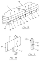
- the roller pallets 1 and 1A shown in Figures 10 and 13 each have a construction which overall is similar to the roller pallet as discussed with reference to Figures 1 to 9 but modifications are included in the couplings 20 and 20A.
- the coupling is indicated at 20' as being longitudinally displaceable in the track 5A.
- the track 5A is of substantially "T" section comprising an oblong rectangular sectioned cavity part 10' which communicates with the slot 11.
- the coupling 20' has a bolt 21' which is of rectangular section complementary to the cavity part 10 in which it is received to be longitudinally slidable therein. Carried on the bolt 21' are two lugs 22' and 23' similarly disposed to the lugs 22 and 23 in the arrangement of Figure 8.
- the lugs 22' and 23' are pivotally mounted on the bolt 21' to be capable of hinged movement relative to the bolt 21' about hinge lines 50 which extend parallel to the longitudinal axis of the bolt.
- the bolt 21' is non-rotatable in the cavity 10' of the track 5A.
- the lugs 22' and 23' to be pivotted on their hinges 50 to a position in which they project through the slot 11 so that the lugs can move longitudinally within the slot.
- the hinged lugs 22' and 23' are pivotted relative to the bolt 21' so that they snap engage in the respective seatings (30, 31 or 32) in a similar manner to that previously described to restrain longitudinal displacement between the coupling 20' and one or both of the platforms 1 and 1A.
- the coupling 20' is conveniently formed as a one piece moulding in plastics so that the lugs 22' and 23' are carried on the bolt 21' through integral plastics hinges (best seen at 50 in Figure 12).
- the track 5A is of similar "T" section to that shown in Figure 10.
- a coupling 20'' Carried by the track 5A is a coupling 20'' which comprises a longitudinally extending bolt 21'' which is of rectangular section complementary to the cavity part 10' and is longitudinally slidably received in that cavity part.
- Each end of the bolt 21'' is provided with a longitudinal extension 60 (for convenience only one such extension is shown in Figure 13, it being appreciated that the extension at the opposite end of the bolt 21'' is a duplicate of that shown at 60).
- the extension 60 is norrower than the width of the slot 11 and is pivotally mounted on the bolt 21'' (to constitute part of the coupling 20' ) through a hinge 61 so that it is capable of displacement relative to the bolt about a laterally extending axis as indicated at 61 in Figure 13.
- Carried on each extension 60 is a stud 62.
- holes 63 Provided in the base of the cavity part 10' of the track 5A are holes 63 at positions which may be considered as seatings disposed in a similar array to those shown at 30 to 32 in Figure 10.
- the extensions 60 can be displaced relative to the non-rotatable bolt 21'' so that the extensions project through the slot 11 to be convenient to hold for displacing the bolt 21'' along the track 5A (as the extensions 60 move along the track 11).
- the extensions 60 are displaced about their hinges so that the studs 62 are press fitted as a friction fit, possibly with snap engagement, into holes 63 in the track or tracks.
- the free end of each extension 60 is provided with a chamfer or undercut 64 to facilitate holding of the extension to withdraw the stud 62 from the hole 63 when repositioning of the coupling is required.
- the coupling 20'' is formed as a one piece plastics moulding to provide an integral plastics hinge 61 between each extension 60 and the bolt 21''.
Landscapes
- Engineering & Computer Science (AREA)
- Transportation (AREA)
- Mechanical Engineering (AREA)
- Chemical & Material Sciences (AREA)
- Combustion & Propulsion (AREA)
- Pallets (AREA)
- Connection Of Plates (AREA)
- Auxiliary Methods And Devices For Loading And Unloading (AREA)
- Bridges Or Land Bridges (AREA)
Applications Claiming Priority (4)
| Application Number | Priority Date | Filing Date | Title |
|---|---|---|---|
| GB9609928 | 1996-05-13 | ||
| GBGB9609928.8A GB9609928D0 (en) | 1996-05-13 | 1996-05-13 | A roller platform |
| GB9611548 | 1996-06-03 | ||
| GB9611548A GB2313103B (en) | 1996-05-13 | 1996-06-03 | A roller platform |
Publications (3)
| Publication Number | Publication Date |
|---|---|
| EP0807563A2 true EP0807563A2 (de) | 1997-11-19 |
| EP0807563A3 EP0807563A3 (de) | 1998-09-09 |
| EP0807563B1 EP0807563B1 (de) | 2002-01-09 |
Family
ID=26309318
Family Applications (1)
| Application Number | Title | Priority Date | Filing Date |
|---|---|---|---|
| EP19960307769 Expired - Lifetime EP0807563B1 (de) | 1996-05-13 | 1996-10-28 | Rollpalette |
Country Status (2)
| Country | Link |
|---|---|
| EP (1) | EP0807563B1 (de) |
| DE (1) | DE69618444D1 (de) |
Cited By (7)
| Publication number | Priority date | Publication date | Assignee | Title |
|---|---|---|---|---|
| EP2058150A1 (de) * | 2007-11-08 | 2009-05-13 | Linpac Allibert Europe | Plattform mit Rollen |
| FR2955839A1 (fr) * | 2010-02-02 | 2011-08-05 | Gerard Bertrand | Palette formee par l'accouplement reversible de plusieurs sous-elements |
| WO2017078753A1 (en) * | 2015-11-06 | 2017-05-11 | Orbis Corporation | Connectable dolly |
| AT15389U1 (de) * | 2015-08-31 | 2017-07-15 | Cabka Gmbh & Co Kg | Display-Palette aus Kunststoff |
| US10086973B2 (en) | 2015-12-30 | 2018-10-02 | Orbis Corporation | Pallet and dolly with bail arm |
| US10279830B2 (en) | 2016-11-08 | 2019-05-07 | Orbis Corporation | Dished caster wheel pocket for a platform or dolly |
| US12558930B2 (en) | 2021-02-08 | 2026-02-24 | Orbis Corporation | Detachable dolly training connector |
Family Cites Families (4)
| Publication number | Priority date | Publication date | Assignee | Title |
|---|---|---|---|---|
| DE2507709A1 (de) * | 1975-02-22 | 1976-09-02 | Brueggemann & Brand Kg | Palette zur aufnahme von ladegut |
| DE3538188A1 (de) * | 1985-03-28 | 1986-10-09 | Aluminium-Walzwerke Singen Gmbh, 7700 Singen | Verbundelement aus zwei aneinander festliegenden profilelementen |
| GB2263684A (en) * | 1992-02-03 | 1993-08-04 | Lin Pac Mouldings | Interlockable pallets. |
| GB2280166B (en) * | 1993-07-12 | 1997-01-29 | Lin Pac Mouldings | A mobile platform assembly |
-
1996
- 1996-10-28 EP EP19960307769 patent/EP0807563B1/de not_active Expired - Lifetime
- 1996-10-28 DE DE69618444T patent/DE69618444D1/de not_active Expired - Lifetime
Non-Patent Citations (1)
| Title |
|---|
| None |
Cited By (9)
| Publication number | Priority date | Publication date | Assignee | Title |
|---|---|---|---|---|
| EP2058150A1 (de) * | 2007-11-08 | 2009-05-13 | Linpac Allibert Europe | Plattform mit Rollen |
| FR2923443A1 (fr) * | 2007-11-08 | 2009-05-15 | Linpac Allibert Europ Soc Par | Plateforme a roulettes. |
| FR2955839A1 (fr) * | 2010-02-02 | 2011-08-05 | Gerard Bertrand | Palette formee par l'accouplement reversible de plusieurs sous-elements |
| AT15389U1 (de) * | 2015-08-31 | 2017-07-15 | Cabka Gmbh & Co Kg | Display-Palette aus Kunststoff |
| WO2017078753A1 (en) * | 2015-11-06 | 2017-05-11 | Orbis Corporation | Connectable dolly |
| US9988062B2 (en) | 2015-11-06 | 2018-06-05 | Orbis Corporation | Connectable dolly |
| US10086973B2 (en) | 2015-12-30 | 2018-10-02 | Orbis Corporation | Pallet and dolly with bail arm |
| US10279830B2 (en) | 2016-11-08 | 2019-05-07 | Orbis Corporation | Dished caster wheel pocket for a platform or dolly |
| US12558930B2 (en) | 2021-02-08 | 2026-02-24 | Orbis Corporation | Detachable dolly training connector |
Also Published As
| Publication number | Publication date |
|---|---|
| DE69618444D1 (de) | 2002-02-14 |
| EP0807563A3 (de) | 1998-09-09 |
| EP0807563B1 (de) | 2002-01-09 |
Similar Documents
| Publication | Publication Date | Title |
|---|---|---|
| EP0691117B1 (de) | Verbindungseinrichtung zum wahlweisen Verbinden einer Patientenlagerfläche mit der Stützsäule eines Operationstisches | |
| AU709267B2 (en) | Container with swivelling sidewalls | |
| EP1305145B1 (de) | Werkzeugkoffer | |
| US5617953A (en) | Stackable/nestable containers | |
| US5868049A (en) | Screw and driver system | |
| US5101969A (en) | Split box, in particular for bottles | |
| DE60015930T2 (de) | Indizierte palette | |
| EP0807563B1 (de) | Rollpalette | |
| EP0189301A2 (de) | Zerlegbarer Transportbehälter | |
| EP3587294B1 (de) | Stapelbarer behälter mit verbindungsmechanismus | |
| JPH026707B2 (de) | ||
| EP0955224A2 (de) | Zusammenklappbarer, handgeführter Wagen | |
| GB2313103A (en) | Coupling mobile platforms | |
| US5190172A (en) | Connection assembly and method for a structural rack | |
| EP1125818B1 (de) | Mobile Plattform | |
| EP4046548A1 (de) | Displaysockel-viertelpalettenbefestigung | |
| DE10020587B4 (de) | Transportroller | |
| DE102019004349B4 (de) | Adapter zur transportsicheren Kopplung von Kästen, wie Werkzeugkästen, und tragbare Werkzeugkastenanordnungen zur bequemen und transportsicheren Aufstapelung und Transport | |
| AU617969B2 (en) | Interlocking sections for portable floors and the like | |
| GB2263684A (en) | Interlockable pallets. | |
| US5870958A (en) | Duplex pallet | |
| EP2226265B1 (de) | Behälter mit Deckel und Verschlussriegel | |
| WO1995023096A1 (de) | Spritzgegossener einrand-kunststoffbehälter mit einrastbarem deckel | |
| EP3712084B1 (de) | Behälter aus kunststoff | |
| CN223174555U (zh) | 一种可折叠物流托盘 |
Legal Events
| Date | Code | Title | Description |
|---|---|---|---|
| PUAI | Public reference made under article 153(3) epc to a published international application that has entered the european phase |
Free format text: ORIGINAL CODE: 0009012 |
|
| AK | Designated contracting states |
Kind code of ref document: A2 Designated state(s): BE DE FR NL |
|
| PUAL | Search report despatched |
Free format text: ORIGINAL CODE: 0009013 |
|
| AK | Designated contracting states |
Kind code of ref document: A3 Designated state(s): BE DE FR NL |
|
| 17P | Request for examination filed |
Effective date: 19980912 |
|
| GRAG | Despatch of communication of intention to grant |
Free format text: ORIGINAL CODE: EPIDOS AGRA |
|
| 17Q | First examination report despatched |
Effective date: 20010508 |
|
| GRAG | Despatch of communication of intention to grant |
Free format text: ORIGINAL CODE: EPIDOS AGRA |
|
| GRAH | Despatch of communication of intention to grant a patent |
Free format text: ORIGINAL CODE: EPIDOS IGRA |
|
| GRAH | Despatch of communication of intention to grant a patent |
Free format text: ORIGINAL CODE: EPIDOS IGRA |
|
| GRAA | (expected) grant |
Free format text: ORIGINAL CODE: 0009210 |
|
| AK | Designated contracting states |
Kind code of ref document: B1 Designated state(s): BE DE FR NL |
|
| PG25 | Lapsed in a contracting state [announced via postgrant information from national office to epo] |
Ref country code: NL Free format text: LAPSE BECAUSE OF FAILURE TO SUBMIT A TRANSLATION OF THE DESCRIPTION OR TO PAY THE FEE WITHIN THE PRESCRIBED TIME-LIMIT Effective date: 20020109 Ref country code: BE Free format text: LAPSE BECAUSE OF FAILURE TO SUBMIT A TRANSLATION OF THE DESCRIPTION OR TO PAY THE FEE WITHIN THE PRESCRIBED TIME-LIMIT Effective date: 20020109 |
|
| REF | Corresponds to: |
Ref document number: 69618444 Country of ref document: DE Date of ref document: 20020214 |
|
| PG25 | Lapsed in a contracting state [announced via postgrant information from national office to epo] |
Ref country code: DE Free format text: LAPSE BECAUSE OF FAILURE TO SUBMIT A TRANSLATION OF THE DESCRIPTION OR TO PAY THE FEE WITHIN THE PRESCRIBED TIME-LIMIT Effective date: 20020410 |
|
| ET | Fr: translation filed | ||
| NLV1 | Nl: lapsed or annulled due to failure to fulfill the requirements of art. 29p and 29m of the patents act | ||
| PLBE | No opposition filed within time limit |
Free format text: ORIGINAL CODE: 0009261 |
|
| STAA | Information on the status of an ep patent application or granted ep patent |
Free format text: STATUS: NO OPPOSITION FILED WITHIN TIME LIMIT |
|
| 26N | No opposition filed | ||
| NLV1 | Nl: lapsed or annulled due to failure to fulfill the requirements of art. 29p and 29m of the patents act | ||
| PGFP | Annual fee paid to national office [announced via postgrant information from national office to epo] |
Ref country code: FR Payment date: 20031003 Year of fee payment: 8 |
|
| PG25 | Lapsed in a contracting state [announced via postgrant information from national office to epo] |
Ref country code: FR Free format text: LAPSE BECAUSE OF NON-PAYMENT OF DUE FEES Effective date: 20050630 |
|
| REG | Reference to a national code |
Ref country code: FR Ref legal event code: ST |