EP0807554A2 - Dispositif de fixation d'une fiche électrique dans une position d'accès difficile, en particulier dans un véhicule automobile - Google Patents
Dispositif de fixation d'une fiche électrique dans une position d'accès difficile, en particulier dans un véhicule automobile Download PDFInfo
- Publication number
- EP0807554A2 EP0807554A2 EP97201165A EP97201165A EP0807554A2 EP 0807554 A2 EP0807554 A2 EP 0807554A2 EP 97201165 A EP97201165 A EP 97201165A EP 97201165 A EP97201165 A EP 97201165A EP 0807554 A2 EP0807554 A2 EP 0807554A2
- Authority
- EP
- European Patent Office
- Prior art keywords
- sliding carriage
- carriage part
- plug
- handle
- rocker
- Prior art date
- Legal status (The legal status is an assumption and is not a legal conclusion. Google has not performed a legal analysis and makes no representation as to the accuracy of the status listed.)
- Granted
Links
Images




Classifications
-
- H—ELECTRICITY
- H01—ELECTRIC ELEMENTS
- H01R—ELECTRICALLY-CONDUCTIVE CONNECTIONS; STRUCTURAL ASSOCIATIONS OF A PLURALITY OF MUTUALLY-INSULATED ELECTRICAL CONNECTING ELEMENTS; COUPLING DEVICES; CURRENT COLLECTORS
- H01R43/00—Apparatus or processes specially adapted for manufacturing, assembling, maintaining, or repairing of line connectors or current collectors or for joining electric conductors
- H01R43/26—Apparatus or processes specially adapted for manufacturing, assembling, maintaining, or repairing of line connectors or current collectors or for joining electric conductors for engaging or disengaging the two parts of a coupling device
Definitions
- the invention is aimed at a device of the type specified in the introductory part of claim 1.
- electric plugs also have to be fastened at poorly accessible points.
- a seat frame in a motor vehicle where a whole series of plugs have to be fixed beneath the seat may serve as an example.
- the contacts in the interior of these plugs are connected to electric leads which serve, e.g. for the control system of a seat adjuster, a seat heater, a device for tightening the belt in the event of an accident, a triggering device for an air bag or lead to further electrically operated devices.
- the plugs must be connected to or disconnected from corresponding mating connectors which for their part have opposite contacts. These opposite contacts are connected to electric supply or control leads which belong, e.g. to a loom of cables laid in fixed manner in the bodywork.
- connection and disconnection is a complicated process; two hands are needed in order to hold the plug with one hand and to guide the mating connector into it in targeted manner with the other hand. In doing so it is difficult to determine visually whether after this troublesome procedure the plug and its mating connector are properly connected. Faulty connections can result in grave consequences in the event of an accident. Even in the case of an adjustment of the seat there is the risk that the plugs disengage unnoticed from the mating connectors and the contact is broken or at least becomes imperfect.
- the object underlying the invention is to develop a device of the type specified in the introductory part of claim 1 which permits reliable and comfortable connection and disconnection between the mating connectors and the plugs. This is achieved according to the invention by means of the measures quoted in the characterising part of claim 1, to which the following special significance is attached.
- a mating connector can be connected easily when the sliding carriage part assumes its first position, that is the run-out position, on the fixed rail part.
- the handling of the mating connector is convenient; it is already possible to recognise readily by eye whether the mating connector is properly connected in the plug or not.
- This run-out position is only temporary and exists only during the assembly or disassembly of the component provided with the plug, e.g. a motor vehicle seat.
- the final position which is not visible and difficult to access in the motor vehicle, can, however, be reached easily in the case of the invention because the sliding carriage part with the plugs and mating connectors previously connected to one another can be transferred with ease on the rail part into its second position, that is a retracted position.
- the plug arrives only subsequently after the completed connection of the mating connector at the poorly accessible position in the motor vehicle. Both positions are secured by means of stopping and opposing stopping members which are arranged between the sliding carriage part or a handle located on it on the one hand and the rail part on the other hand. By operating the handle against a spring loading acting on it the stopping and opposing stopping members are detached from one another and readily permit a displacement of the sliding carriage part between its two aforementioned positions. This allows handling with only a single hand; after connecting up the mating connector in the run-out position the handle on the sliding carriage part need only be operated in order to bring the sliding carriage part into its final retracted position.
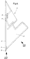
- the device according to the invention consists of two parts 20, 30, that is to say of a rail part 20 shown in Figures 6, 7 and 8 and of a sliding carriage part 30 illustrated in Figure 5. Both parts 20, 30 of the device are mirror symmetrical in construction with respect to their longitudinal centre.
- the rail part 20 comprises longitudinal rails 21, which are best seen in figures 7 and 8 and on which the sliding carriage part 30 with a U-shaped guide 23 can be pushed in the direction of the arrows 16 of Figure 1 and can be pushed out in the direction of the arrows 16' of Figure 1 or Figure 12.
- the rail part 20 also further possesses a profiled housing 22 which serves for the static attachment of the rail part 20 to the frame 11 of a seat 10 according to Figure 1.
- the attachment of the rail part 20 to the seat frame 11 ensues through a snap-on spring 12 which engages behind an assembly rail 13 according to Figure 1, and by means of one or more fastening screws 14, which are anchored in the seat frame 11. These screws 14 also hold the assembly rail 13 fast.
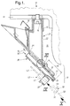
- the assembled rail part 20 is located at a poorly accessible position 15 labelled by 15 in Figure 1 beneath the seat 10.
- the sliding carriage part 30 serves for fixing an assemblage of plugs of which only one plug 40 is illustrated by dotted lines in Figure 1 and several plugs 40 are illustrated in Figure 9.
- a corresponding number of profiled casings 32 formed on the sliding carriage part 30, which are best seen in Figure 9, serve this purpose.
- the associated plugs 40 with their correspondingly coded opposite profile are indicated in outline by dotted lines.
- the plugs 40 are held fast in the casings 32 assigned to them in their correct plug-in positions by means of latching or end limit stops.
- the plugs 40 fitted in the casings 32 are carried along with it.
- the contacts 41 indicated in Figure 1 and provided in the interior of the plugs 40 are connected to corresponding electric leads 42 which lead to sundry devices arranged in the region of the seat, such as, e.g. a seat heater.
- sundry devices arranged in the region of the seat, such as, e.g. a seat heater.
- the individual plugs 40 are held together as a set of plugs by means of the casings 32 formed on the sliding carriage part 30.
- a corresponding set of mating connectors 50 which advantageously adhere together and can be seen in rear view in Figure 10.
- These mating connectors 50 for their part possess opposite contacts 51 which, as is indicated schematically in Figure 1, are connected to electric leads 52.
- These leads 52 can belong to leads of a loom of cables laid in fixed manner in the bodywork of the vehicle.
- This set of mating connectors 50 according to Figure 10 can be connected in very convenient manner to the plugs 40 mounted in the sliding carriage part 30, as long as the sliding carriage 30 is located in a first defined position shown in Figures 1 and 9 on the rail part 20 fastened in fixed manner to the seat 10.
- this first position is characterised in that the plugs 40 mounted in the sliding carriage part 30 are located in the open space 17 beneath the seat 10 and are therefore conveniently accessible for the manual connecting up of the mating connectors 50.
- Figure 2 where the mating connector is guided by one hand in the direction of the arrow 18 into the rigidly positioned plug 40 but in Figure 2 has not yet reached its final connecting position in the plug 40; the contacts 41 have not yet come into proper electrical connection to the opposite contacts 51.
- the sliding carriage part 30 In this first position, the sliding carriage part 30 is located with a substantial section of its length 19 in a run-out position in front of the rail part 20 installed rigidly on the seat 10, for which reason this position of the sliding carriage part 30 is to be designated below in short as the "run-out position".
- This run-out position of the sliding carriage part 30 is fixed by two stopping and opposing stopping members 33, 23 and 34, 24 working together with one another in pairs.
- the opposing stopping members 23, 24 are located on the rail part 20 while one stopping member 33 is formed on the sliding carriage part 30 in the region of a special handle 35 and the other stopping member 34 is formed in the region of the aforementioned U-shaped guide 31 of the sliding carriage part 30.
- the handle 35 and the stopping members 33, 34 are designed in one piece with the sliding carriage part 30 constructed of elastic synthetic material and together with the aforementioned U-shaped guide 31 and the casings 32 form a coherent body as is best seen in Figure 5.
- the sliding carriage part has the following structure discernible in Figures 2 and 5.
- the handle 35 consists of the free end of a rocker 36 which is formed on the back end 37 of the sliding carriage part 30 and is separated from its peripheral guides 31 by slots which have been cut free.
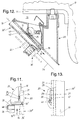
- the stopping member 34 is here one component of a toothed directed locking mechanism 24, 34 shown in detail in Figure 11.
- the stopping member here consists of a locking tooth 34 with a sawtooth profile which is formed on the U-guide 31 and the steep side of which engages behind a corresponding opposing locking tooth 24 on the steep side of the latter in the run-out position.
- the locking tooth 34 on the sliding carriage side is provided in duplicate, that is to say on each of the two U-guides 31 and projects into the open space above the rocker 36.
- the opposing locking tooth 24 on the rail side is likewise arranged in duplicate and is located in the region of the peripheral longitudinal rails 21, but as can be seen from the plan view of Figure 8, it is raised up into a higher plane colliding with the locking tooth 34.
- the steep sides of the two teeth 34, 34' engage behind one another as stated and thus prevent a push-out movement of the sliding carriage part 30 in the direction of the push-out arrow 16'.
- the further push-in movement in the direction of the arrow 16 of Figure 1 still to be described in more detail is readily possible from this run-out position of Figure 11.
- FIG. 11 From Figure 11 it can also finally be gathered how a sliding carriage part 30 can be fitted on the rail part 20.
- the position of the sliding carriage part detached from the rail part 20 is labelled in Figure 11 by 30'' and is to be designated in short as the "disassembly position" in what follows.
- the sliding carriage part 30'' is plugged by its back end 37 discernible in Figure 5, which is advantageously pointed according to Figure 2, on to the advantageously likewise pointed front edge 23 of the rail part 20 according to Figures 6 and 7. This initiating plug-on movement is illustrated in Figure 11 by the arrow 16''.
- the further push-in movement 16 from the run-out position shown pulled out in Figure 11 is, however, not possible because this is prevented by the further pair of stopping and opposing stopping members 33, 23.
- the stopping and opposing stopping member 33, 23 are the two components of a locking mechanism here likewise provided in duplicate.
- the rocker 36 is provided at both peripheral edges with a locking elevation 33 which strikes against the aforementioned front edge 23 of the slide part.
- the push-in movement 16 of the sliding carriage part illustrated by the dotted arrow 16 in Figure 2 is initially blocked.
- the sliding carriage part 30 can thus neither be pushed in further in the direction of the arrow 16 nor be pushed out further in the direction of the arrow 16'.
- the run-out position 30 of the sliding carriage in Figure 2 is thus fixed.
- the mating connector possesses a radial projection 53 which points towards the rocker 36. If the mating connector 50 is only partially inserted into the plug 40, as Figure 2 shows, then its projection 53 travels under the handle 35 of the rocker 36 and blocks its actuation made plain by the dotted arrow 43' in Figure 2. The handle 35 is blocked. The two components 23, 33 of the locking mechanism between the sliding carriage part and rail part 30, 20 are secured in their engagement. Thus it is precluded that the sliding carriage part 30 can be conveyed into the final pushed-in position 30' of Figure 12 in the case of such an imperfect coupling position of the two plugs 40, 50. This is possible only in the complete connection position of Figure 3.
- the blockage of the actuation 43' of the rocker 36 described in Figure 2 is given in the present case in that the mating connector projection 53 strikes against a catch 38 which is located in the region at the end of the rocker handle 35.
- the starting pivot position of the rocker 36 according to Figures 2 and 3 is essentially determined by two additional spring tongues 39 which, as Figure 5 shows, are positioned on both sides of this catch 38.
- the spring tongues 39 are S-shaped and one arc of the S is formed in the region of the rocker handle 35, while the other arc of the S is seated in the region of the casings 32 for fixing the plugs 40.
- the projection 53 comes into the region of a recess 44 provided on the rocker 36.
- this recess 44 consists simply of the open space enclosed by the two lateral S-spring tongues 39 behind the catch 38.
- the mating connector projection 53 moves into this recess 44.
- the spring tongue 39 I strongly deformed and after release of the rocker handle 35 strives to switch over from its release pivot position 36' of Figure 4 to its starting pivot position 36 of Figure 3.
- One pair of members 45, 25 consists again of a locking mechanism, that is to say, as can best be seen in Figure 5, of a further locking elevation 45 on the rocker 36 and of a counterlocking edge 25 which can be seen in Figure 12.
- this counterlocking edge 25 acts in the opposite direction and normally precludes the push-out movement of the sliding carriage part discernible by means of the arrow 16' in Figure 12.
- the opposite movement 16 in the direction of the dotted arrow in Figure 12 is also blocked because the members 46, 26 are now effective as limit stops and fundamentally preclude a further movement.
- the sliding carriage part 30 possesses two limit stop members 46 preceded by run-up slopes 47 arranged in the region of the two U-guides 31.
- the sliding carriage part 20 possesses on its housing 22 two lateral flaps 28 opposite one another, the front flap edge 26 of which forms the limit stop edge working together with the limit stop member 46.
- the further push-in movement of the sliding carriage part located in the retracted position 30' is fundamentally precluded.
- the locking elevation 33 is preceded by a sloping ramp 48 with which the interfering components on the sliding carriage part 20 are surmounted by means of an automatic elastic outswing movement; during the push-out movement 16' of Figure 3 the locking elevation 33 snaps automatically behind the locking edge 23.
Landscapes
- Engineering & Computer Science (AREA)
- Manufacturing & Machinery (AREA)
- Details Of Connecting Devices For Male And Female Coupling (AREA)
- Seats For Vehicles (AREA)
Applications Claiming Priority (2)
| Application Number | Priority Date | Filing Date | Title |
|---|---|---|---|
| DE19619978A DE19619978C2 (de) | 1996-05-17 | 1996-05-17 | Vorrichtung zum Kuppeln bzw. Entkuppeln wenigstens einer Steckverbindung an einer schwer zugänglichen Stelle, insbesondere am Sitzgestell in einem Fahrzeug |
| DE19619978 | 1996-05-17 |
Publications (3)
| Publication Number | Publication Date |
|---|---|
| EP0807554A2 true EP0807554A2 (fr) | 1997-11-19 |
| EP0807554A3 EP0807554A3 (fr) | 1998-04-22 |
| EP0807554B1 EP0807554B1 (fr) | 2003-04-16 |
Family
ID=7794613
Family Applications (1)
| Application Number | Title | Priority Date | Filing Date |
|---|---|---|---|
| EP97201165A Expired - Lifetime EP0807554B1 (fr) | 1996-05-17 | 1997-04-21 | Dispositif de fixation d'une fiche électrique dans une position d'accès difficile, en particulier dans un véhicule automobile |
Country Status (2)
| Country | Link |
|---|---|
| EP (1) | EP0807554B1 (fr) |
| DE (2) | DE19619978C2 (fr) |
Families Citing this family (2)
| Publication number | Priority date | Publication date | Assignee | Title |
|---|---|---|---|---|
| IT1308388B1 (it) † | 1999-02-23 | 2001-12-17 | Valeo Sicurezza Abitacolo Spa | Maniglia per una porta di un veicolo. |
| DE102020112834A1 (de) | 2020-05-12 | 2021-11-18 | Bayerische Motoren Werke Aktiengesellschaft | Schutzvorrichtung und Schutzverfahren für einen elektrischen Außenanschluss an einem Kraftfahrzeug |
Family Cites Families (8)
| Publication number | Priority date | Publication date | Assignee | Title |
|---|---|---|---|---|
| DE2453043A1 (de) * | 1974-11-08 | 1976-05-13 | Philips Patentverwaltung | Steckverbindung fuer elektrische geraete |
| US4371743A (en) * | 1981-03-27 | 1983-02-01 | General Motors Corporation | Hinged pull-down fuse block assembly |
| IT8153864U1 (it) * | 1981-12-03 | 1983-06-03 | Fiat Auto Spa | Gruppo porta fusibili per autoveicoli. |
| US4482176A (en) * | 1982-08-02 | 1984-11-13 | General Motors Corporation | Manually operable latch for hinged pull-down member |
| US4963098A (en) * | 1988-02-26 | 1990-10-16 | Amp Incorporated | Blind mate shielded input/output connector assembly |
| JP2500239Y2 (ja) * | 1990-10-02 | 1996-06-05 | 矢崎総業株式会社 | コネクタの固定構造 |
| FR2681986B1 (fr) * | 1991-09-30 | 1995-07-07 | Peugeot | Connecteur, notamment pour faisceau electrique de vehicule automobile. |
| DE9410617U1 (de) * | 1994-07-01 | 1994-08-18 | Telegärtner Gerätebau GmbH, 01774 Höckendorf | Einschub für einen Schaltschrank |
-
1996
- 1996-05-17 DE DE19619978A patent/DE19619978C2/de not_active Expired - Fee Related
-
1997
- 1997-04-21 DE DE69720848T patent/DE69720848T2/de not_active Expired - Fee Related
- 1997-04-21 EP EP97201165A patent/EP0807554B1/fr not_active Expired - Lifetime
Also Published As
| Publication number | Publication date |
|---|---|
| EP0807554A3 (fr) | 1998-04-22 |
| DE69720848T2 (de) | 2004-01-29 |
| DE69720848D1 (de) | 2003-05-22 |
| DE19619978C2 (de) | 1999-04-08 |
| DE19619978A1 (de) | 1997-11-20 |
| EP0807554B1 (fr) | 2003-04-16 |
Similar Documents
| Publication | Publication Date | Title |
|---|---|---|
| US5624271A (en) | Connector latch interlock plate | |
| EP0855308B1 (fr) | Ensemble d'alimentation électrique et procédé d'installation d'un élément de construction pour véhicule automobile | |
| US5586902A (en) | Electric connector | |
| US5203719A (en) | Lock assurance mechanism for connector | |
| EP0734100B1 (fr) | Connecteur électrique avec une position finale assurée | |
| US5279507A (en) | Connector for use in vehicles | |
| US5879180A (en) | Electric connector | |
| EP0624925B1 (fr) | Connecteur électrique avec fonction de détection d'enfichage | |
| EP0714806B1 (fr) | Siège de sécurité d'enfants pour des véhicules automobiles | |
| US5127847A (en) | Connector engagement detecting apparatus | |
| EP0703113A2 (fr) | Siège de sécurité pour enfants dans des véhicules | |
| EP0045139B1 (fr) | Structure empêchant une porte coulissante d'un véhicule automobile de se mouvoir verticalement | |
| EP0619202A1 (fr) | Siège de sécurité pour enfants dans des véhicules | |
| US5438492A (en) | End release seat belt buckle | |
| EP1248328B1 (fr) | Détecteur de couplage pour connecteur | |
| US4334701A (en) | Coupling for a vehicle seat belt | |
| US5707248A (en) | Device for preventing a wrong coupling of a connector | |
| IE54934B1 (en) | Latchable tab receptacle or electrical flat socket and electrical connector provided therewith | |
| EP0807554B1 (fr) | Dispositif de fixation d'une fiche électrique dans une position d'accès difficile, en particulier dans un véhicule automobile | |
| EP0321169B1 (fr) | Connecteur électrique rendant possible la prévention d'un couplage incomplet | |
| US4647070A (en) | Latch device for movable anchor in passive seat belt system | |
| WO1997029290A1 (fr) | Connecteur de cable | |
| EP1378970A1 (fr) | Structure de connection de connecteurs | |
| US4517422A (en) | Electrical switch having interlocked blower and air conditioner switch components for vehicles | |
| US5993226A (en) | Structure for coupling connectors |
Legal Events
| Date | Code | Title | Description |
|---|---|---|---|
| PUAI | Public reference made under article 153(3) epc to a published international application that has entered the european phase |
Free format text: ORIGINAL CODE: 0009012 |
|
| AK | Designated contracting states |
Kind code of ref document: A2 Designated state(s): DE ES FR GB IT |
|
| PUAL | Search report despatched |
Free format text: ORIGINAL CODE: 0009013 |
|
| AK | Designated contracting states |
Kind code of ref document: A3 Designated state(s): DE ES FR GB IT |
|
| 17P | Request for examination filed |
Effective date: 19981022 |
|
| GRAH | Despatch of communication of intention to grant a patent |
Free format text: ORIGINAL CODE: EPIDOS IGRA |
|
| GRAH | Despatch of communication of intention to grant a patent |
Free format text: ORIGINAL CODE: EPIDOS IGRA |
|
| GRAA | (expected) grant |
Free format text: ORIGINAL CODE: 0009210 |
|
| AK | Designated contracting states |
Designated state(s): DE ES FR GB IT |
|
| REG | Reference to a national code |
Ref country code: GB Ref legal event code: FG4D |
|
| REF | Corresponds to: |
Ref document number: 69720848 Country of ref document: DE Date of ref document: 20030522 Kind code of ref document: P |
|
| PG25 | Lapsed in a contracting state [announced via postgrant information from national office to epo] |
Ref country code: GB Free format text: LAPSE BECAUSE OF NON-PAYMENT OF DUE FEES Effective date: 20030716 |
|
| PG25 | Lapsed in a contracting state [announced via postgrant information from national office to epo] |
Ref country code: ES Free format text: LAPSE BECAUSE OF FAILURE TO SUBMIT A TRANSLATION OF THE DESCRIPTION OR TO PAY THE FEE WITHIN THE PRESCRIBED TIME-LIMIT Effective date: 20031030 |
|
| ET | Fr: translation filed | ||
| PLBE | No opposition filed within time limit |
Free format text: ORIGINAL CODE: 0009261 |
|
| STAA | Information on the status of an ep patent application or granted ep patent |
Free format text: STATUS: NO OPPOSITION FILED WITHIN TIME LIMIT |
|
| GBPC | Gb: european patent ceased through non-payment of renewal fee |
Effective date: 20030716 |
|
| 26N | No opposition filed |
Effective date: 20040119 |
|
| PGFP | Annual fee paid to national office [announced via postgrant information from national office to epo] |
Ref country code: FR Payment date: 20050418 Year of fee payment: 9 |
|
| PGFP | Annual fee paid to national office [announced via postgrant information from national office to epo] |
Ref country code: DE Payment date: 20050630 Year of fee payment: 9 |
|
| PGFP | Annual fee paid to national office [announced via postgrant information from national office to epo] |
Ref country code: IT Payment date: 20060430 Year of fee payment: 10 |
|
| PG25 | Lapsed in a contracting state [announced via postgrant information from national office to epo] |
Ref country code: DE Free format text: LAPSE BECAUSE OF NON-PAYMENT OF DUE FEES Effective date: 20061101 |
|
| REG | Reference to a national code |
Ref country code: FR Ref legal event code: ST Effective date: 20061230 |
|
| PG25 | Lapsed in a contracting state [announced via postgrant information from national office to epo] |
Ref country code: FR Free format text: LAPSE BECAUSE OF NON-PAYMENT OF DUE FEES Effective date: 20060502 |
|
| PG25 | Lapsed in a contracting state [announced via postgrant information from national office to epo] |
Ref country code: IT Free format text: LAPSE BECAUSE OF NON-PAYMENT OF DUE FEES Effective date: 20070421 |