EP0807485A2 - Laser drilling of non-circular apertures - Google Patents
Laser drilling of non-circular apertures Download PDFInfo
- Publication number
- EP0807485A2 EP0807485A2 EP97303194A EP97303194A EP0807485A2 EP 0807485 A2 EP0807485 A2 EP 0807485A2 EP 97303194 A EP97303194 A EP 97303194A EP 97303194 A EP97303194 A EP 97303194A EP 0807485 A2 EP0807485 A2 EP 0807485A2
- Authority
- EP
- European Patent Office
- Prior art keywords
- diffuser
- laser
- metal
- wall
- laser beam
- Prior art date
- Legal status (The legal status is an assumption and is not a legal conclusion. Google has not performed a legal analysis and makes no representation as to the accuracy of the status listed.)
- Granted
Links
Images

Classifications
-
- B—PERFORMING OPERATIONS; TRANSPORTING
- B23—MACHINE TOOLS; METAL-WORKING NOT OTHERWISE PROVIDED FOR
- B23K—SOLDERING OR UNSOLDERING; WELDING; CLADDING OR PLATING BY SOLDERING OR WELDING; CUTTING BY APPLYING HEAT LOCALLY, e.g. FLAME CUTTING; WORKING BY LASER BEAM
- B23K26/00—Working by laser beam, e.g. welding, cutting or boring
- B23K26/02—Positioning or observing the workpiece, e.g. with respect to the point of impact; Aligning, aiming or focusing the laser beam
- B23K26/06—Shaping the laser beam, e.g. by masks or multi-focusing
- B23K26/062—Shaping the laser beam, e.g. by masks or multi-focusing by direct control of the laser beam
- B23K26/0622—Shaping the laser beam, e.g. by masks or multi-focusing by direct control of the laser beam by shaping pulses
-
- B—PERFORMING OPERATIONS; TRANSPORTING
- B23—MACHINE TOOLS; METAL-WORKING NOT OTHERWISE PROVIDED FOR
- B23K—SOLDERING OR UNSOLDERING; WELDING; CLADDING OR PLATING BY SOLDERING OR WELDING; CUTTING BY APPLYING HEAT LOCALLY, e.g. FLAME CUTTING; WORKING BY LASER BEAM
- B23K26/00—Working by laser beam, e.g. welding, cutting or boring
- B23K26/36—Removing material
- B23K26/38—Removing material by boring or cutting
- B23K26/382—Removing material by boring or cutting by boring
- B23K26/384—Removing material by boring or cutting by boring of specially shaped holes
-
- B—PERFORMING OPERATIONS; TRANSPORTING
- B23—MACHINE TOOLS; METAL-WORKING NOT OTHERWISE PROVIDED FOR
- B23K—SOLDERING OR UNSOLDERING; WELDING; CLADDING OR PLATING BY SOLDERING OR WELDING; CUTTING BY APPLYING HEAT LOCALLY, e.g. FLAME CUTTING; WORKING BY LASER BEAM
- B23K26/00—Working by laser beam, e.g. welding, cutting or boring
- B23K26/36—Removing material
- B23K26/38—Removing material by boring or cutting
- B23K26/382—Removing material by boring or cutting by boring
- B23K26/389—Removing material by boring or cutting by boring of fluid openings, e.g. nozzles, jets
-
- B—PERFORMING OPERATIONS; TRANSPORTING
- B23—MACHINE TOOLS; METAL-WORKING NOT OTHERWISE PROVIDED FOR
- B23K—SOLDERING OR UNSOLDERING; WELDING; CLADDING OR PLATING BY SOLDERING OR WELDING; CUTTING BY APPLYING HEAT LOCALLY, e.g. FLAME CUTTING; WORKING BY LASER BEAM
- B23K2101/00—Articles made by soldering, welding or cutting
- B23K2101/001—Turbines
Definitions
- the present invention relates generally to laser beam machining and, more specifically, to laser beam machining of non-circular cross-section apertures.
- a gas turbine engine includes a compressor for compressing air, which is mixed with fuel and ignited for generating hot combustion gases in a combustor with energy being extracted from the gases in a turbine, disposed downstream of the combustor for powering the compressor and providing output power.
- One conventional cooling arrangement includes film cooling holes which are typically inclined at an acute angle through the component for receiving a portion of the compressed air on one side thereof which passes through the holes to form a film of cooling air along the opposite side of the component which provides effective film cooling of the component during operation. Film cooling holes are typically found in combustion liners, turbine nozzle vanes and blades, turbine shrouds, and various shields requiring effective cooling.
- a film cooling hole is a diffuser hole or a shaped hole.
- a diffuser hole or slot is formed with an exit area on the surface of the component to be cooled and the exit area is larger than its entrance area.
- a circular or otherwise shaped constant area feed hole is formed from the other surface of the component to the entrance area of the diffuser portion of the aperture. From the apertures, the cooling air is discharged along the cooled surface for creating a continuous cooling air film within the boundary for cooling the component.
- each pulse has an amplitude and a finite duration, each typically having a plus or minus 5% variation in value.
- the power of each pulse the amount of energy in each pulse, may be determined which can have about a plus or minus 20% variation based on the worst case combination of the plus and minus 5% variations on pulse amplitude and duration.
- This substantial energy variation means that the amount of metal vaporized per pulse varies significantly from pulse to pulse, with the corresponding aperture being formed by consecutive pulses, varying significantly in configuration during the process.
- This significant pulse energy variation is typically not a major concern for drilling or laser cutting, since the objective is to form a through hole or cut, with the configuration of the in-process hole or cut being immaterial.
- Turbine film cooled components are typically relatively thin in overall thickness, which requires the accurate placement and depth of the blind aperture and diffuser hole or slot therein. If the remaining base material below the diffuser is too thin, the components may have undesirably low strength either reducing its useful life or requiring rejection of the component during the manufacturing process.
- conventional EDM machining may be used for accurately forming the blind diffuser, followed in turn by forming the required through holes in the slot, again using conventional EDM machining or conventional laser drilling.
- EDM machining would typically be performed in two separate and distinct steps utilizing refixturing the component in the same or different machines to form the differently configured blind slot and through holes in the component.
- Refixturing presents the additional problem of maintaining accurate alignment between the blind diffuser and the feed holes therein. Accordingly, the resulting manufacturing process would be relatively complex and costly since a typical component such as a turbine blade, turbine vane, or combustion liner has a substantial number of film cooling through holes, with the corresponding large number of blind apertures associated therewith and many blades and vanes are manufactured with these film cooling apertures.
- a method for forming an aperture in a component wall made of metal, the aperture having a diffuser which opens up and outward from the bottom of the diffuser to a first surface of the wall includes the following steps: A) laser machining the wall with a laser which produces a laser beam having a pulse rate and power sufficient to vaporize the metal; B) firing and traversing the laser beam, preferably at an acute angle across the surface to a predetermined first edge of the diffuser in a single pass starting at a centerline of the diffuser; and C) traversing the laser beam at an increasing rate of speed during the pass so that each beam pulse vaporizes the metal at a laser spot such that successive laser spots substantially overlap each other in decreasing amounts and the pulses nibble out the metal to form a continuous trench below the surface.
- a method of forming a plurality of cooling apertures through a wall made of metal and having outer and inner surfaces, each of the apertures including a diffuser having longitudinally paced apart forward and aft edges and transversely paced apart first and second side edges, and which opens up and outward from a bottom of the diffuser to the first surface of the component wall comprising the following steps for each aperture: A) laser machining the wall with a laser which produces a laser beam having a pulse rate and power to vaporize the metal; B) laser drilling a feed and centering hole with the laser beam on the first surface of the wall in about a center of the diffuser; C) traversing the laser beam at an acute angle latitudinally across the surface along the aft edge to the first side edge of the diffuser in a single pass starting at a longitudinally extending centerline of the diffuser and at an increasing rate of speed so that each beam pulse vaporizes the wall metal at a spot such that successive laser hit
- the traversing is preferably done linearly with the acute angle held constant during all of the traversals and starting from a centerline towards a predetermined first side edge of the diffuser and a second trench connecting to and collinear with the previously formed first trench is formed in the same manner by traversing the laser beam across the surface to an opposite predetermined second side edge of the diffuser to form one long continuous trench.
- Multiple adjacent long trenches are formed from one of the side edges to the opposite side edge by linearly traversing the laser beam and vaporizing the metal along parallel lines of spots so that adjacent lines of spots at least abut and preferably overlap.
- the adjacent long trenches may have different lengths.
- the adjacent trenches narrow in length in a direction normal to lengths of the trenches so as to form a substantially trapezoidal-shaped diffuser.
- the diffuser may be formed by using two or more sequences of the traversals wherein each of the traversals starts at about the centerline of the diffuser going outward towards one of the side edges.
- a centering hole is first formed with at least one shot of the laser beam on the first surface of the wall in about a center of the diffuser.
- a more particular method uses the laser to drill a feed hole entirely through the wall such that when the entire aperture is finished the feed hole extends part way, such as about half way, into the wall from an opposite surface to the first surface of the wall and to the bottom of the diffuser.
- the method of the present invention may be used for forming a plurality of cooling apertures through a wall made of metal such as a cooled turbine airfoil of a blade or vane or a combustor liner.
- FIG. 1 is a schematic representation of an exemplary multi-axis machine supporting a component such as an exemplary hollow coolable gas turbine engine rotor blade in a corresponding fixture, and a laser beam for machining apertures such as slots and holes in the component in accordance with one embodiment of the present invention.
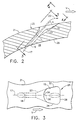
- FIG. 2 is a sectional view of a portion of the airfoil of the turbine blade illustrated in FIG. 1 taken generally along line 2-2 through an exemplary cooling aperture formed therein.
- FIG. 3 is a sectional view through a portion of the airfoil slot illustrated in FIG. 1 and taken generally along line 3-3.
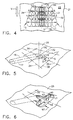
- FIG. 4 is an elevational view of a diffuser portion of a cooling aperture being laser machined through the wall and taken along line 4-4 to illustrate laser formation of the non-circular diffuser portion therein followed in turn by laser drilling of the feed hole through the rest of the wall below the diffuser.
- FIG. 5 is a perspective view illustrating the laser formation of the feed and centering hole in accordance with the exemplary embodiment of the present invention.
- FIG. 6 is a perspective view illustrating the laser formation of a first trench of the diffuser in accordance with the exemplary embodiment of the present invention.
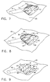
- FIG. 7 is a perspective view illustrating the laser formation of an adjacent and overlapping second trench of the diffuser in accordance with the exemplary embodiment of the present invention.
- FIG. 8 is a perspective view illustrating the laser formation of an adjacent and overlapping third trench of the diffuser made with a first sequence of laser beam traversals illustrated in FIG. 4 and in accordance with the exemplary embodiment of the present invention.
- FIG. 9 is a perspective view illustrating the completed aperture having been made with two sequences of laser beam traversals illustrated in FIG. 4 and in accordance with the exemplary embodiment of the present invention.
- FIG. 1 Illustrated schematically in FIG. 1 is a conventional multi-axis machine 10, which may be conventionally configured for providing three to eight axes of motion of a metal component, such as a gas turbine engine turbine rotor blade 8 having an airfoil 12 for example.
- the blade 8 is integrally formed and the airfoil 12 is generally hollow and is integrally joined to a conventional dovetail 11 and a platform 13 therebetween from which the airfoil extends in a radial direction R.
- the airfoil 12 is conventionally configured with leading and trailing edges LE and TE, respectively, and a concave pressure side CC, and a convex suction side CV extending therebetween.
- the airfoil 12 is otherwise conventional except for a couple of rows of a plurality of laser formed longitudinally or radially spaced apart blind apertures 14 formed through an airfoil wall 21.
- Each of the apertures 14 having a generally downstream V facing non-circular cross-sectional diffuser 15 connected to and in fluid supply communication with a feed hole 16 which are disposed in flow communication with an inner cavity or channel 18 as more particularly shown in FIG. 2.
- the channel 18 is conventionally provided with film cooling air 20 during operation, as shown by the flow arrows illustrated in FIG.
- the aperture 14 and its film cooling diffuser 15 and the feed holes 16 supplying the cooling air 20 thereto are shown in the pressure surface of the airfoil 12, they may also be used on the suction surface thereof, or in any other hot component in a gas turbine engine or other structure subjected to a hot fluid such as the combustion gases for effecting film cooling of the components.
- the diffuser 15 and feed hole 16 may be similarly configured in an otherwise conventional gas turbine engine combustion liner, turbine nozzle vane, turbine rotor shroud, or other components designed to use film cooling.
- FIGS. 2 and 3 illustrate, in more particularity, an exemplary one of the apertures 14 and the corresponding through feed holes 16 disposed in flow communication between the diffuser 15 and the interior channel 18 of the airfoil 12 in final form.
- the blade 8 is suitably fixedly supported in a suitable fixture 22 shown schematically in the multi-axis machine 10 so that the blade may be moved in the various degrees of movement of the machine 10, which may be typically three to eight translational and rotational axes of movement.
- the fixture 22 may take any conventional form for fixedly holding the blade 8 during manufacturing.
- the machine 10 is in the form of a conventional computer numerical control (CNC) machine for providing accurate movement of the blade 8 during the manufacturing process.
- CNC computer numerical control
- the machine 10 further includes a conventional industrial laser 24 suitably fixedly joined relative thereto.
- the laser 24 itself includes various blades, such as a focusing lens 24a, and is conventional in configuration but operated in accordance with the present invention as further described hereinbelow.
- the laser 24 is operated in-turn for both machining or forming the individual non-circular cross-sectional diffusers 15 and the corresponding feed holes 16 for each of the apertures 14 in a simple, inexpensive, and accurate manufacturing process.
- the laser 24 is preferably a conventional ND:YAG laser configured in accordance with the present invention for machining in turn the corresponding feed holes 16 and the diffuser 15 therein.
- the present invention may be used to form other types of non-circular cross-sectional apertures or excavations that may not use feed holes and/or have purposes and uses different from that of the exemplary diffuser 15.
- the exemplary aperture 14 has a circular cross-section feed hole 16 with an axis 17 and a trapezoidal cross-section diffuser 15.
- the diffuser 15 has a centerline 30 which intersects the axis 17 and is parallel to first and second side edges 32 and 34, respectively, of the diffuser. Parallel forward and aft edges 36 and 38, respectively, of the diffuser 15 are perpendicular to the centerline 30 and are acutely angled relative to the first and second side edges 32 and 34, respectively.
- the trapezoidal cross-sectional shape of the diffuser 15 is highly rounded at its corners C between sidewalls W and a wall ramp WR as is more particularly shown in FIG. 9.
- Each diffuser 15 opens up and outward from a bottom 23 of the diffuser to an outer surface 25 of the wall 21.
- the invention provides a laser machining method to form the apertures 14 in the wall 21 which is made of metal.
- the laser 24 is first used to produce a laser beam 24b to form the circular cross-section feed hole 16 by aiming the laser beam along the axis 17 and firing it until the feed hole is complete.
- the feed hole 16 also serves as a centering hole and so is preferably laser drilled first with the laser 24 to help properly shape the diffuser 15 during its machining.
- the diffuser is formed by using the laser 24 to produce laser beam 24b having a pulse rate and power sufficient to vaporize the metal of the wall 21 in a nibbling action by firing and traversing the laser beam, preferably, at a constant acute angle A across the outer surface 25 to the predetermined first side edge 32 of the diffuser in a single pass starting at a centerline of the diffuser 15.
- a first traversal 1, of the laser beam 24b is done from the centerline 30 to the first side edge 32.
- the first traversal 1 and all subsequent traversals are done at an increasing rate of speed during the traversal so that each beam pulse vaporizes the metal at a laser spot S, indicated by circles so marked, such that successive laser spots substantially overlap each other in decreasing amounts.
- This allows the pulses to nibble out the metal to form a first trench 40 having a width WT below the outer surface 25 and shapes the diffuser 15 to give provide a smooth integration at the corners C between the sidewalls W and the wall ramp WR.
- the traversing is preferably done linearly and the acute angle A is preferably held constant with respect to an exit plane 15E of the diffuser 15 defined by the first and second side edges 32 and 34, respectively, and the forward and aft edges 36 and 38, respectively.
- the acute angle A is preferably at the same angle as that of the axis 17 of the centering and feed hole 16.
- the increasing rate of speed during the traversal may be accomplished by setting the feed rate of the multi-axis machine 10 at a constant setting and then simultaneously starting the machine and the laser pulsing so that the traversing begins to accelerate towards the setting value but stops and the laser ceases firing before actually reaching that value.
- a second trench 42 having the same width WT of and collinear with the previously formed first trench 40 is formed in a similar manner by a second traversal 2 of the laser beam 24b from the centerline 30 to the second side edge 34 to form a first long trench 43 having an average first length L1.
- Multiple, 3 in the exemplary embodiment herein, adjacent long trenches are formed between the first and second side edges 32 and 34, respectively by linearly traversing the laser beam and vaporizing the metal along parallel lines of spots S to form multiple adjacent long trenches so that adjacent lines of spots at least abut and preferably overlap. This is illustrated in FIGS. 4, 7 and 8, which indicate adjacent second and third overlapping long trenches, 44 and 46 respectively, having successively shorter average second and third lengths L2 and L3, respectively.
- the second long trench 44 is made by third and fourth traversals 3 and 4 and the third long trench 46 is made by firth and sixth traversals 5 and 6, respectively.
- the adjacent long trenches may have different lengths (L1-L3) as illustrated in the exemplary embodiment and adjacent trenches narrow in length in a direction normal to lengths of the trenches, i.e. from the forward edge 36 to the aft edge 38 so as to form a substantially trapezoidal cross-section shaped diffuser 15.
- the diffuser may be formed by using two or more sequences of the traversals 1-6, or any other number of traversals, above to form layers of nibbled out long trenches wherein each of the traversals starts at about the centerline of the diffuser going outward towards one of the side edges and the acute angle A is preferably held constant with respect to the exit plane 15E of the diffuser 15.
- successive spots in turn do not overlap each other so as to be sufficiently spaced apart from each other for spreading apart the pulse energy at the spots.
- successive pulses operate on the same spot, with the pulse energy thereof adding together for vaporizing the material at the common spot and drilling a hole through the material.
- This conventional drilling operation concentrates the laser energy and typically also enlarges the spot size greater than the nominal diameter of the pulse during operation due to the concentrated heat and its relatively large heat affected zone. This makes control of the trench difficult and causes jagged surfaces.
- the present invention is operated to prevent the concentration of pulse energy at any one spot by rapidly traversing the laser beam 24b so that the pulse energy and corresponding spots S are spread apart laterally to distribute the energy.
- the laser beam pulse energy may be distributed along the diffuser and effectively averaged out thereacross. This effectively accommodates the large pulse energy variation discussed above which can be as large as about plus or minus 20% to nevertheless accurately form the diffuser 15.
- the resulting diameter of the trenches is substantially equal to the diameter D of the individual spots S and dimensions of diffuser can be accurately machined to provide substantially straight forward and aft edges 36 and 38, and first and second side edges 32 and 34, respectively.
- the increasing rate of speed during the traversal provides that the longitudinal sidewalls W of the diffuser 15 and the wall ramp WR formed, thereby, are relatively smooth in surface with relatively few irregularities therein for obtaining suitably smooth aerodynamic performance during operation of the diffuser in its intended film cooling environment.
- An exemplary embodiment of the cooling aperture has the diameter D of the laser beam 24b and one of the corresponding spots S in the exemplary range of 7-15 mils.
- the laser 24 in the exemplary form of the ND:YAG laser may be operated with a conventional average power in the range of about 30-300 watts, with a preferred pulse rate in accordance with the present invention in the preferred range of about 10-50 Hz, and with a pulse duration in the conventional range of about 0.6-2.0 milliseconds (ms).
- the machine 10 may be conventionally operated for traversing the airfoil 12 relative to the stationary laser 24 so that the laser beam 24b is traversed at an accelerating rate by setting the machines feed rate in the preferred range of about 10-50 inches/minute in accordance with the present invention to form the diffuser at least two sequences of complete traversals.
- a more particular method uses the laser 24 and laser beam 24b to drill the feed hole 16 entirely through the wall 21 such that when the entire aperture is finished the feed hole extends part way, such as about half way, into the wall from an inner surface 26 to the outer surface 25 of the wall and to the bottom of the diffuser 15.
- the method of the present invention may be used for forming a plurality of cooling apertures through a wall made of metal such as a cooled turbine airfoil of a blade or vane or a combustor liner.
Landscapes
- Physics & Mathematics (AREA)
- Optics & Photonics (AREA)
- Engineering & Computer Science (AREA)
- Plasma & Fusion (AREA)
- Mechanical Engineering (AREA)
- Laser Beam Processing (AREA)
- Turbine Rotor Nozzle Sealing (AREA)
Abstract
Description
- The present invention relates generally to laser beam machining and, more specifically, to laser beam machining of non-circular cross-section apertures.
- A gas turbine engine includes a compressor for compressing air, which is mixed with fuel and ignited for generating hot combustion gases in a combustor with energy being extracted from the gases in a turbine, disposed downstream of the combustor for powering the compressor and providing output power. Various components bound the hot combustion gases and, therefore, are typically cooled during operation for obtaining a useful life thereof. One conventional cooling arrangement includes film cooling holes which are typically inclined at an acute angle through the component for receiving a portion of the compressed air on one side thereof which passes through the holes to form a film of cooling air along the opposite side of the component which provides effective film cooling of the component during operation. Film cooling holes are typically found in combustion liners, turbine nozzle vanes and blades, turbine shrouds, and various shields requiring effective cooling. One particular type of a film cooling hole is a diffuser hole or a shaped hole. Typically, a diffuser hole or slot is formed with an exit area on the surface of the component to be cooled and the exit area is larger than its entrance area. Often a circular or otherwise shaped constant area feed hole is formed from the other surface of the component to the entrance area of the diffuser portion of the aperture. From the apertures, the cooling air is discharged along the cooled surface for creating a continuous cooling air film within the boundary for cooling the component.
- Conventional processes exist for forming through holes in gas turbine engine components such as disclosed wherein holes may be drilled using an industrial laser or electrical discharge machining (EDM). In conventional laser drilling, a suitably powered laser beam is maintained at a desired location as the beam vaporizes metal until the through hole is completed. The laser, such as a ND:YAG laser, is typically operated at a suitable pulse rate with each pulse vaporizing a portion of the metal until the entire hole is completed.
- However, methods to form these so-called blind apertures in the component for the improved film cooling diffuser apertures or slots, creates significant problems and costs. There is also a desire to form these non-circular cross-sectional diffuser portions of the aperture in an inexpensive manner while still being able to provide effective film cooling. The sidewalls and bottom of the slot should preferably be relatively smooth for aerodynamic reasons for efficient film cooling operation. The walls and bottom should also be sufficiently smooth to avoid undesirable stress concentrations for limiting maximum stress in the component during operation for providing a long life.
- In the typical YAG pulse laser, each pulse has an amplitude and a finite duration, each typically having a plus or minus 5% variation in value. By integrating over time, the power of each pulse, the amount of energy in each pulse, may be determined which can have about a plus or minus 20% variation based on the worst case combination of the plus and minus 5% variations on pulse amplitude and duration. This substantial energy variation means that the amount of metal vaporized per pulse varies significantly from pulse to pulse, with the corresponding aperture being formed by consecutive pulses, varying significantly in configuration during the process. This significant pulse energy variation is typically not a major concern for drilling or laser cutting, since the objective is to form a through hole or cut, with the configuration of the in-process hole or cut being immaterial.
- However, this substantial energy variation is quite significant for attempting to form blind non-circular holes or slots which do not pass completely through the metal component. Accordingly, attempting to use a laser in conventional practice to drill a blind hole and, then, continue the process for forming an elongated non-circular hole or blind slot, will result in a diffuser portion of the aperture having a substantial variation in width, depth and surface contour. The resulting jagged contour diffuser would be undesirable for aerodynamic and strength reasons. The jagged contour decreases the ability to form a substantially smooth and uniform cooling air film and the jagged bottom of the slot could undesirably decrease the effective strength of the base portion of the component below the slot bottom. Turbine film cooled components are typically relatively thin in overall thickness, which requires the accurate placement and depth of the blind aperture and diffuser hole or slot therein. If the remaining base material below the diffuser is too thin, the components may have undesirably low strength either reducing its useful life or requiring rejection of the component during the manufacturing process.
- Alternatively, conventional EDM machining may be used for accurately forming the blind diffuser, followed in turn by forming the required through holes in the slot, again using conventional EDM machining or conventional laser drilling. These two processes would typically be performed in two separate and distinct steps utilizing refixturing the component in the same or different machines to form the differently configured blind slot and through holes in the component. Refixturing presents the additional problem of maintaining accurate alignment between the blind diffuser and the feed holes therein. Accordingly, the resulting manufacturing process would be relatively complex and costly since a typical component such as a turbine blade, turbine vane, or combustion liner has a substantial number of film cooling through holes, with the corresponding large number of blind apertures associated therewith and many blades and vanes are manufactured with these film cooling apertures.
- According to the invention a method for forming an aperture in a component wall made of metal, the aperture having a diffuser which opens up and outward from the bottom of the diffuser to a first surface of the wall, includes the following steps: A) laser machining the wall with a laser which produces a laser beam having a pulse rate and power sufficient to vaporize the metal; B) firing and traversing the laser beam, preferably at an acute angle across the surface to a predetermined first edge of the diffuser in a single pass starting at a centerline of the diffuser; and C) traversing the laser beam at an increasing rate of speed during the pass so that each beam pulse vaporizes the metal at a laser spot such that successive laser spots substantially overlap each other in decreasing amounts and the pulses nibble out the metal to form a continuous trench below the surface.
- Further, according to the invention, there is provided a method of forming a plurality of cooling apertures through a wall made of metal and having outer and inner surfaces, each of the apertures including a diffuser having longitudinally paced apart forward and aft edges and transversely paced apart first and second side edges, and which opens up and outward from a bottom of the diffuser to the first surface of the component wall, said method comprising the following steps for each aperture: A) laser machining the wall with a laser which produces a laser beam having a pulse rate and power to vaporize the metal; B) laser drilling a feed and centering hole with the laser beam on the first surface of the wall in about a center of the diffuser; C) traversing the laser beam at an acute angle latitudinally across the surface along the aft edge to the first side edge of the diffuser in a single pass starting at a longitudinally extending centerline of the diffuser and at an increasing rate of speed so that each beam pulse vaporizes the wall metal at a spot such that successive laser hit spots substantially overlap each other in decreasing amounts so that the pulses nibble out the metal to collectively form a continuous portion of a trench of decreasing depth below the surface; and D) traversing the laser beam at the acute angle latitudinally across the surface to the opposite second side edge of the diffuser in a single pass starting at the longitudinally extending centerline of the diffuser and at an increasing rate of speed so that each beam pulse vaporizes the metal at a spot such that successive laser hit spots substantially overlap each other in decreasing amounts so that the pulses nibble out the metal to collectively form a continuous remaining portion of the trench of decreasing depth below the surface.
- The traversing is preferably done linearly with the acute angle held constant during all of the traversals and starting from a centerline towards a predetermined first side edge of the diffuser and a second trench connecting to and collinear with the previously formed first trench is formed in the same manner by traversing the laser beam across the surface to an opposite predetermined second side edge of the diffuser to form one long continuous trench. Multiple adjacent long trenches are formed from one of the side edges to the opposite side edge by linearly traversing the laser beam and vaporizing the metal along parallel lines of spots so that adjacent lines of spots at least abut and preferably overlap. The adjacent long trenches may have different lengths. In one more particular embodiment, the adjacent trenches narrow in length in a direction normal to lengths of the trenches so as to form a substantially trapezoidal-shaped diffuser. The diffuser may be formed by using two or more sequences of the traversals wherein each of the traversals starts at about the centerline of the diffuser going outward towards one of the side edges.
- According to one embodiment, a centering hole is first formed with at least one shot of the laser beam on the first surface of the wall in about a center of the diffuser. A more particular method uses the laser to drill a feed hole entirely through the wall such that when the entire aperture is finished the feed hole extends part way, such as about half way, into the wall from an opposite surface to the first surface of the wall and to the bottom of the diffuser. The method of the present invention may be used for forming a plurality of cooling apertures through a wall made of metal such as a cooled turbine airfoil of a blade or vane or a combustor liner.
- The invention will now be described in greater detail, by way of example, with reference to the drawings in which:
- FIG. 1 is a schematic representation of an exemplary multi-axis machine supporting a component such as an exemplary hollow coolable gas turbine engine rotor blade in a corresponding fixture, and a laser beam for machining apertures such as slots and holes in the component in accordance with one embodiment of the present invention.
- FIG. 2 is a sectional view of a portion of the airfoil of the turbine blade illustrated in FIG. 1 taken generally along line 2-2 through an exemplary cooling aperture formed therein.
- FIG. 3 is a sectional view through a portion of the airfoil slot illustrated in FIG. 1 and taken generally along line 3-3.
- FIG. 4 is an elevational view of a diffuser portion of a cooling aperture being laser machined through the wall and taken along line 4-4 to illustrate laser formation of the non-circular diffuser portion therein followed in turn by laser drilling of the feed hole through the rest of the wall below the diffuser.
- FIG. 5 is a perspective view illustrating the laser formation of the feed and centering hole in accordance with the exemplary embodiment of the present invention.
- FIG. 6 is a perspective view illustrating the laser formation of a first trench of the diffuser in accordance with the exemplary embodiment of the present invention.
- FIG. 7 is a perspective view illustrating the laser formation of an adjacent and overlapping second trench of the diffuser in accordance with the exemplary embodiment of the present invention.
- FIG. 8 is a perspective view illustrating the laser formation of an adjacent and overlapping third trench of the diffuser made with a first sequence of laser beam traversals illustrated in FIG. 4 and in accordance with the exemplary embodiment of the present invention.
- FIG. 9 is a perspective view illustrating the completed aperture having been made with two sequences of laser beam traversals illustrated in FIG. 4 and in accordance with the exemplary embodiment of the present invention.
- While the preferred embodiment of our invention has been described fully in order to explain its principles, it is understood that various modifications or alterations may be made to the preferred embodiment without departing from the scope of the invention as set forth in the appended claims.
- Illustrated schematically in FIG. 1 is a conventional
multi-axis machine 10, which may be conventionally configured for providing three to eight axes of motion of a metal component, such as a gas turbine engineturbine rotor blade 8 having anairfoil 12 for example. In the exemplary embodiment illustrated, theblade 8 is integrally formed and theairfoil 12 is generally hollow and is integrally joined to aconventional dovetail 11 and aplatform 13 therebetween from which the airfoil extends in a radial direction R. Theairfoil 12 is conventionally configured with leading and trailing edges LE and TE, respectively, and a concave pressure side CC, and a convex suction side CV extending therebetween. Theairfoil 12 is otherwise conventional except for a couple of rows of a plurality of laser formed longitudinally or radially spaced apartblind apertures 14 formed through anairfoil wall 21. Each of theapertures 14 having a generally downstream V facing non-circularcross-sectional diffuser 15 connected to and in fluid supply communication with afeed hole 16 which are disposed in flow communication with an inner cavity orchannel 18 as more particularly shown in FIG. 2. Thechannel 18 is conventionally provided withfilm cooling air 20 during operation, as shown by the flow arrows illustrated in FIG. 1, which is discharged from the interior of theairfoil 12 through theseveral feed holes 16 to feed thediffuser 15 and form a radially continuous film of cooling air for cooling theairfoil 12 during operation against the heat of hot combustion gases which flow thereover during engine operation. - Although the
aperture 14 and its film cooling diffuser 15 and thefeed holes 16 supplying thecooling air 20 thereto are shown in the pressure surface of theairfoil 12, they may also be used on the suction surface thereof, or in any other hot component in a gas turbine engine or other structure subjected to a hot fluid such as the combustion gases for effecting film cooling of the components. For example, thediffuser 15 andfeed hole 16 may be similarly configured in an otherwise conventional gas turbine engine combustion liner, turbine nozzle vane, turbine rotor shroud, or other components designed to use film cooling. - In accordance with the present invention, it is desired to form or machine the
diffusers 15 andfeed holes 16 in a relatively inexpensive, relatively fast, and relatively accurate process for reducing cost of manufacture since in a typical individual gas turbine engine component, there may be a greatmany diffusers 15 and a corresponding number offeed holes 16, and a substantial number of the individual components must be formed. FIGS. 2 and 3 illustrate, in more particularity, an exemplary one of theapertures 14 and the corresponding throughfeed holes 16 disposed in flow communication between thediffuser 15 and theinterior channel 18 of theairfoil 12 in final form. - As shown schematically in FIG. 1, the
blade 8 is suitably fixedly supported in asuitable fixture 22 shown schematically in themulti-axis machine 10 so that the blade may be moved in the various degrees of movement of themachine 10, which may be typically three to eight translational and rotational axes of movement. Thefixture 22 may take any conventional form for fixedly holding theblade 8 during manufacturing. Themachine 10 is in the form of a conventional computer numerical control (CNC) machine for providing accurate movement of theblade 8 during the manufacturing process. - The
machine 10 further includes a conventionalindustrial laser 24 suitably fixedly joined relative thereto. Thelaser 24 itself includes various blades, such as a focusinglens 24a, and is conventional in configuration but operated in accordance with the present invention as further described hereinbelow. In accordance with the present invention, thelaser 24 is operated in-turn for both machining or forming the individual non-circularcross-sectional diffusers 15 and the corresponding feed holes 16 for each of theapertures 14 in a simple, inexpensive, and accurate manufacturing process. In the exemplary embodiment illustrated in FIG. 1, thelaser 24 is preferably a conventional ND:YAG laser configured in accordance with the present invention for machining in turn the corresponding feed holes 16 and thediffuser 15 therein. The present invention may be used to form other types of non-circular cross-sectional apertures or excavations that may not use feed holes and/or have purposes and uses different from that of theexemplary diffuser 15. - The
exemplary aperture 14 has a circularcross-section feed hole 16 with anaxis 17 and atrapezoidal cross-section diffuser 15. Thediffuser 15 has acenterline 30 which intersects theaxis 17 and is parallel to first and second side edges 32 and 34, respectively, of the diffuser. Parallel forward andaft edges diffuser 15 are perpendicular to thecenterline 30 and are acutely angled relative to the first and second side edges 32 and 34, respectively. Note that the trapezoidal cross-sectional shape of thediffuser 15 is highly rounded at its corners C between sidewalls W and a wall ramp WR as is more particularly shown in FIG. 9. Eachdiffuser 15 opens up and outward from a bottom 23 of the diffuser to anouter surface 25 of thewall 21. - The invention provides a laser machining method to form the
apertures 14 in thewall 21 which is made of metal. Preferably, thelaser 24 is first used to produce alaser beam 24b to form the circularcross-section feed hole 16 by aiming the laser beam along theaxis 17 and firing it until the feed hole is complete. Thefeed hole 16 also serves as a centering hole and so is preferably laser drilled first with thelaser 24 to help properly shape thediffuser 15 during its machining. Next, the diffuser is formed by using thelaser 24 to producelaser beam 24b having a pulse rate and power sufficient to vaporize the metal of thewall 21 in a nibbling action by firing and traversing the laser beam, preferably, at a constant acute angle A across theouter surface 25 to the predeterminedfirst side edge 32 of the diffuser in a single pass starting at a centerline of thediffuser 15. - As illustrated in FIGS. 4 and 6, a first traversal 1, of the
laser beam 24b is done from thecenterline 30 to thefirst side edge 32. The first traversal 1 and all subsequent traversals are done at an increasing rate of speed during the traversal so that each beam pulse vaporizes the metal at a laser spot S, indicated by circles so marked, such that successive laser spots substantially overlap each other in decreasing amounts. This allows the pulses to nibble out the metal to form afirst trench 40 having a width WT below theouter surface 25 and shapes thediffuser 15 to give provide a smooth integration at the corners C between the sidewalls W and the wall ramp WR. The traversing is preferably done linearly and the acute angle A is preferably held constant with respect to anexit plane 15E of thediffuser 15 defined by the first and second side edges 32 and 34, respectively, and the forward andaft edges axis 17 of the centering and feedhole 16. The increasing rate of speed during the traversal may be accomplished by setting the feed rate of themulti-axis machine 10 at a constant setting and then simultaneously starting the machine and the laser pulsing so that the traversing begins to accelerate towards the setting value but stops and the laser ceases firing before actually reaching that value. - A
second trench 42 having the same width WT of and collinear with the previously formedfirst trench 40 is formed in a similar manner by asecond traversal 2 of thelaser beam 24b from thecenterline 30 to thesecond side edge 34 to form a firstlong trench 43 having an average first length L1. Multiple, 3 in the exemplary embodiment herein, adjacent long trenches are formed between the first and second side edges 32 and 34, respectively by linearly traversing the laser beam and vaporizing the metal along parallel lines of spots S to form multiple adjacent long trenches so that adjacent lines of spots at least abut and preferably overlap. This is illustrated in FIGS. 4, 7 and 8, which indicate adjacent second and third overlapping long trenches, 44 and 46 respectively, having successively shorter average second and third lengths L2 and L3, respectively. The secondlong trench 44 is made by third and fourth traversals 3 and 4 and the thirdlong trench 46 is made by firth and sixth traversals 5 and 6, respectively. The adjacent long trenches may have different lengths (L1-L3) as illustrated in the exemplary embodiment and adjacent trenches narrow in length in a direction normal to lengths of the trenches, i.e. from theforward edge 36 to theaft edge 38 so as to form a substantially trapezoidal cross-section shapeddiffuser 15. The diffuser may be formed by using two or more sequences of the traversals 1-6, or any other number of traversals, above to form layers of nibbled out long trenches wherein each of the traversals starts at about the centerline of the diffuser going outward towards one of the side edges and the acute angle A is preferably held constant with respect to theexit plane 15E of thediffuser 15. - By using multiple sequences of traversals and suitably selecting the pulse rate and the feed rates, successive spots in turn do not overlap each other so as to be sufficiently spaced apart from each other for spreading apart the pulse energy at the spots. In a conventional drilling operation for example, successive pulses operate on the same spot, with the pulse energy thereof adding together for vaporizing the material at the common spot and drilling a hole through the material. This conventional drilling operation concentrates the laser energy and typically also enlarges the spot size greater than the nominal diameter of the pulse during operation due to the concentrated heat and its relatively large heat affected zone. This makes control of the trench difficult and causes jagged surfaces. In contrast, the present invention is operated to prevent the concentration of pulse energy at any one spot by rapidly traversing the
laser beam 24b so that the pulse energy and corresponding spots S are spread apart laterally to distribute the energy. By forming thediffuser 15 using a series of passes of thelaser beam 24b, with the spots S eventually overlapping each other between successive passes and not in individual passes, the laser beam pulse energy may be distributed along the diffuser and effectively averaged out thereacross. This effectively accommodates the large pulse energy variation discussed above which can be as large as about plus or minus 20% to nevertheless accurately form thediffuser 15. Since the pulse energy is being spread longitudinally along thediffuser 15, the resulting diameter of the trenches is substantially equal to the diameter D of the individual spots S and dimensions of diffuser can be accurately machined to provide substantially straight forward andaft edges diffuser 15 and the wall ramp WR formed, thereby, are relatively smooth in surface with relatively few irregularities therein for obtaining suitably smooth aerodynamic performance during operation of the diffuser in its intended film cooling environment. - An exemplary embodiment of the cooling aperture has the diameter D of the
laser beam 24b and one of the corresponding spots S in the exemplary range of 7-15 mils. Thelaser 24 in the exemplary form of the ND:YAG laser may be operated with a conventional average power in the range of about 30-300 watts, with a preferred pulse rate in accordance with the present invention in the preferred range of about 10-50 Hz, and with a pulse duration in the conventional range of about 0.6-2.0 milliseconds (ms). Themachine 10 may be conventionally operated for traversing theairfoil 12 relative to thestationary laser 24 so that thelaser beam 24b is traversed at an accelerating rate by setting the machines feed rate in the preferred range of about 10-50 inches/minute in accordance with the present invention to form the diffuser at least two sequences of complete traversals. - A more particular method uses the
laser 24 andlaser beam 24b to drill thefeed hole 16 entirely through thewall 21 such that when the entire aperture is finished the feed hole extends part way, such as about half way, into the wall from aninner surface 26 to theouter surface 25 of the wall and to the bottom of thediffuser 15. The method of the present invention may be used for forming a plurality of cooling apertures through a wall made of metal such as a cooled turbine airfoil of a blade or vane or a combustor liner. - While there have been described herein, what are considered to be preferred and exemplary embodiments of the present invention, other modifications of the invention shall be apparent to those skilled in the art from the teachings herein, and it is, therefore, desired to be secured in the appended claims all such modifications as fall within the true spirit and scope of the invention.
- Accordingly, what is desired to be secured by Letters Patent of the United States is the invention as defined and differentiated in the following claims:
Claims (10)
- A method of forming an aperture (14) in a component wall (21) made of metal, the aperture (14) including a diffuser (15) which opens up and outward from a bottom (23) of the diffuser (15) to a first surface (25) of the wall (21), said method comprising the following steps:A) laser machining the wall (21) with a laser (24) which produces a laser beam (24b) having a pulse rate and power sufficient to vaporize the metal;B) firing and traversing the laser beam (24b) at an acute angle (A) across the surface to a predetermined first edge (32) of the diffuser (15) in a single pass starting at a centerline (30) of the diffuser (15); andC) traversing the laser beam (24b) at an increasing rate of speed during said pass so that each beam pulse vaporizes the metal at a laser spot (S) such that successive laser spots (S) substantially overlap each other in decreasing amounts and the pulses nibble out the metal to form a continuous trench (40) below the surface (25).
- A method according to claim 1 wherein a second trench (42) is formed in the same manner by traversing the laser beam (24b) across the surface to an opposite predetermined second edge (34) of the diffuser (15) to form one long continuous trench (43).
- A method according to claim 2 wherein multiple adjacent long trenches (43, 44, 46) are formed from one of the edges (36) to the opposite edge (38) by linearly traversing the laser beam (24b) and vaporizing the metal along parallel lines of spots (S) so that adjacent lines of spots (S) at least abut.
- A method according to claim 3 wherein adjacent lines of spots (S) overlap, the adjacent long trenches have different lengths (L1, L2, L3) and narrow in length in a direction normal to lengths of the trenches so as to form a substantially trapezoidal-shaped diffuser (15).
- A method according to claim 4 further comprising at least two sequences of traversals (1 and 2) wherein each of said traversals starts at about the centerline (30) of the diffuser (15) going outward towards one of the edges (32, 34) and the acute angle (A) is held constant during all of the traversals.
- A method according to claim 5 wherein a centering hole (16) is first formed with at least one shot of the laser beam (24b) on the first surface (25) of the wall (21) in about a center of the diffuser (15).
- A method according to claim 6 further comprising a further step of using the laser (24) to drill a feed hole (16) into the diffuser (15) such that the feed hole (16) extends from a second surface (26) opposite the first surface (25) of the wall (21) and to the bottom (23) of the diffuser (15) wherein the feed hole (16) is formed before the diffuser (15) and the feed hole (16) is used as the centering hole (16).
- A method of forming a plurality of cooling apertures (14) through a wall (21) made of metal and having outer and inner surfaces (25 and 26), each of the apertures (14) including a diffuser (15) having longitudinally paced apart forward and aft edges (36 and 38) and transversely paced apart first and second side edges (32 and 34), and which opens up and outward from a bottom (23) of the diffuser (15) to the first surface (25) of the component wall (21), said method comprising the following steps for each aperture (14):A) laser machining the wall (21) with a laser (24) which produces a laser beam (24b) having a pulse rate and power to vaporize the metal;B) laser drilling a feed and centering hole (16) with the laser beam (24b) on the first surface (25) of the wall (21) in about a center of the diffuser (15);C) traversing the laser beam (24b) at an acute angle (A) latitudinally across the surface along the aft edge (38) to the first side edge (32) of the diffuser (15) in a single pass starting at a longitudinally extending centerline (30) of the diffuser (15) and at an increasing rate of speed so that each beam pulse vaporizes the wall metal at a spot (S) such that successive laser (24) hit spots (S) substantially overlap each other in decreasing amounts so that the pulses nibble out the metal to collectively form a continuous portion of a trench (40) of decreasing depth below the surface; andD) traversing the laser beam (24b) at the acute angle (A) latitudinally across the surface to the opposite second side edge (34) of the diffuser (15) in a single pass starting at the longitudinally extending centerline (30) of the diffuser (15) and at an increasing rate of speed so that each beam pulse vaporizes the metal at a spot (S) such that successive laser (24) hit spots (S) substantially overlap each other in decreasing amounts so that the pulses nibble out the metal to collectively form a continuous remaining portion of the trench (44) of decreasing depth below the surface.
- A method according to claim 8 wherein:
multiple adjacent overlapping ones of the trenches (40, 44) are formed side by side starting from the previously formed trench to the forward edge (36) to form a hollowed out diffuser (15). - A method according to claim 9 wherein more than one series of said traversals (1, 2, 3, 4, 5, 6) are made, the adjacent trenches have different lengths (L1, L2, L3), and the adjacent trenches narrow in length in a direction normal to lengths of the trenches so as to form a substantially trapezoidal-shaped diffuser (15) having parallel forward and aft edges (36 and 38) and acutely angled side edges (32 and 34) between them.
Applications Claiming Priority (2)
| Application Number | Priority Date | Filing Date | Title |
|---|---|---|---|
| US648472 | 1996-05-15 | ||
| US08/648,472 US5609779A (en) | 1996-05-15 | 1996-05-15 | Laser drilling of non-circular apertures |
Publications (3)
| Publication Number | Publication Date |
|---|---|
| EP0807485A2 true EP0807485A2 (en) | 1997-11-19 |
| EP0807485A3 EP0807485A3 (en) | 1999-04-28 |
| EP0807485B1 EP0807485B1 (en) | 2001-12-05 |
Family
ID=24600924
Family Applications (1)
| Application Number | Title | Priority Date | Filing Date |
|---|---|---|---|
| EP97303194A Expired - Lifetime EP0807485B1 (en) | 1996-05-15 | 1997-05-09 | Laser drilling of non-circular apertures |
Country Status (4)
| Country | Link |
|---|---|
| US (1) | US5609779A (en) |
| EP (1) | EP0807485B1 (en) |
| JP (1) | JP3719466B2 (en) |
| DE (1) | DE69708744T2 (en) |
Cited By (2)
| Publication number | Priority date | Publication date | Assignee | Title |
|---|---|---|---|---|
| WO2013165504A2 (en) | 2012-02-15 | 2013-11-07 | United Technologies Corporation | Manufacturing methods for multi-lobed cooling holes |
| CN105458530A (en) * | 2016-01-29 | 2016-04-06 | 孙树峰 | Device and method for machining aviation engine blade film hole through femtosecond lasers |
Families Citing this family (101)
| Publication number | Priority date | Publication date | Assignee | Title |
|---|---|---|---|---|
| US6624382B2 (en) * | 1997-01-30 | 2003-09-23 | Anvik Corporation | Configured-hole high-speed drilling system for micro-via pattern formation, and resulting structure |
| US5881445A (en) * | 1997-07-30 | 1999-03-16 | Mauro; George | Method of producing micro-apertures in optically flat surfaces and structures when made by the method |
| US5837964A (en) * | 1998-01-16 | 1998-11-17 | Chromalloy Gas Turbine Corporation | Laser drilling holes in components by combined percussion and trepan drilling |
| EP0950463B1 (en) * | 1998-03-23 | 2002-01-23 | Alstom | Non-circular cooling hole and method of manufacturing the same |
| DE19960797C1 (en) | 1999-12-16 | 2001-09-13 | Mtu Aero Engines Gmbh | Method for producing an opening in a metallic component |
| US6501045B1 (en) | 2000-04-06 | 2002-12-31 | Resonetics, Inc. | Method and apparatus for controlling the taper angle of the walls of laser machined features |
| US6573474B1 (en) * | 2000-10-18 | 2003-06-03 | Chromalloy Gas Turbine Corporation | Process for drilling holes through a thermal barrier coating |
| US6420677B1 (en) | 2000-12-20 | 2002-07-16 | Chromalloy Gas Turbine Corporation | Laser machining cooling holes in gas turbine components |
| GB0112234D0 (en) | 2001-05-18 | 2001-07-11 | Welding Inst | Surface modification |
| JP2004537175A (en) * | 2001-08-02 | 2004-12-09 | エスケーシー カンパニー,リミテッド | Method for manufacturing chemical mechanical polishing pad using laser |
| GB2381489B (en) * | 2001-10-30 | 2004-11-17 | Rolls Royce Plc | Method of forming a shaped hole |
| EP1317995A1 (en) * | 2001-12-05 | 2003-06-11 | Siemens Aktiengesellschaft | Method and apparatus for smoothing the surface of a gas turbine airfoil |
| US6612811B2 (en) * | 2001-12-12 | 2003-09-02 | General Electric Company | Airfoil for a turbine nozzle of a gas turbine engine and method of making same |
| GB2389554A (en) * | 2002-06-12 | 2003-12-17 | Alstom | Machining apparatus and a method for machining |
| US7411150B2 (en) * | 2002-06-12 | 2008-08-12 | Alstom Technology Ltd. | Method of producing a composite component |
| GB2395157B (en) * | 2002-11-15 | 2005-09-07 | Rolls Royce Plc | Laser driliing shaped holes |
| US6988872B2 (en) | 2003-01-27 | 2006-01-24 | Mitsubishi Heavy Industries, Ltd. | Turbine moving blade and gas turbine |
| GB2389330B (en) * | 2003-03-31 | 2004-05-05 | M J Technologies Ltd | Machining of cooling air holes in gas turbine components |
| DE10335657B4 (en) * | 2003-08-04 | 2015-04-30 | Alstom Technology Ltd. | Parametric production of cooling holes |
| CN1758983B (en) * | 2003-09-30 | 2011-08-17 | 松下电器产业株式会社 | Mold for optical components |
| EP1529580B1 (en) * | 2003-10-29 | 2009-01-07 | Siemens Aktiengesellschaft | Casting mould |
| US7374401B2 (en) * | 2005-03-01 | 2008-05-20 | General Electric Company | Bell-shaped fan cooling holes for turbine airfoil |
| US7784183B2 (en) * | 2005-06-09 | 2010-08-31 | General Electric Company | System and method for adjusting performance of manufacturing operations or steps |
| JP4931507B2 (en) * | 2005-07-26 | 2012-05-16 | スネクマ | Cooling flow path formed in the wall |
| FR2895691A1 (en) * | 2006-01-12 | 2007-07-06 | Snecma Sa | Turbomachine blade wall`s cooling channel forming method, involves piercing wall to make hole by using laser, and forming indentation in wall to form diffusion portion by using electro-erosion electrode |
| EP1967696B1 (en) * | 2005-11-01 | 2017-03-15 | IHI Corporation | Turbine part |
| CA2580102A1 (en) * | 2006-03-06 | 2007-09-06 | General Electric Company | System and method for monitoring drilling process parameters and controlling drilling operation |
| US20070296967A1 (en) * | 2006-06-27 | 2007-12-27 | Bhupendra Kumra Gupta | Analysis of component for presence, composition and/or thickness of coating |
| US20080003096A1 (en) * | 2006-06-29 | 2008-01-03 | United Technologies Corporation | High coverage cooling hole shape |
| US8084706B2 (en) * | 2006-07-20 | 2011-12-27 | Gsi Group Corporation | System and method for laser processing at non-constant velocities |
| EP1892375A1 (en) * | 2006-08-23 | 2008-02-27 | Siemens Aktiengesellschaft | Turbine engine rotor disc with cooling passage |
| EP1898051B8 (en) * | 2006-08-25 | 2017-08-02 | Ansaldo Energia IP UK Limited | Gas turbine airfoil with leading edge cooling |
| US7812282B2 (en) * | 2007-03-15 | 2010-10-12 | Honeywell International Inc. | Methods of forming fan-shaped effusion holes in combustors |
| US7820267B2 (en) * | 2007-08-20 | 2010-10-26 | Honeywell International Inc. | Percussion drilled shaped through hole and method of forming |
| US20090169394A1 (en) * | 2007-12-28 | 2009-07-02 | General Electric Company | Method of forming cooling holes and turbine airfoil with hybrid-formed cooling holes |
| FR2926481B1 (en) * | 2008-01-23 | 2011-09-23 | Snecma | COOLING CHANNEL CLEANING IN A WALL |
| US8246306B2 (en) * | 2008-04-03 | 2012-08-21 | General Electric Company | Airfoil for nozzle and a method of forming the machined contoured passage therein |
| US8057181B1 (en) | 2008-11-07 | 2011-11-15 | Florida Turbine Technologies, Inc. | Multiple expansion film cooling hole for turbine airfoil |
| US8371814B2 (en) * | 2009-06-24 | 2013-02-12 | Honeywell International Inc. | Turbine engine components |
| GB0912796D0 (en) * | 2009-07-23 | 2009-08-26 | Cummins Turbo Tech Ltd | Compressor,turbine and turbocharger |
| US8292583B2 (en) * | 2009-08-13 | 2012-10-23 | Siemens Energy, Inc. | Turbine blade having a constant thickness airfoil skin |
| US8529193B2 (en) * | 2009-11-25 | 2013-09-10 | Honeywell International Inc. | Gas turbine engine components with improved film cooling |
| US8857055B2 (en) * | 2010-01-29 | 2014-10-14 | General Electric Company | Process and system for forming shaped air holes |
| US8905713B2 (en) | 2010-05-28 | 2014-12-09 | General Electric Company | Articles which include chevron film cooling holes, and related processes |
| US8628293B2 (en) * | 2010-06-17 | 2014-01-14 | Honeywell International Inc. | Gas turbine engine components with cooling hole trenches |
| US9696035B2 (en) | 2010-10-29 | 2017-07-04 | General Electric Company | Method of forming a cooling hole by laser drilling |
| US20120102959A1 (en) * | 2010-10-29 | 2012-05-03 | John Howard Starkweather | Substrate with shaped cooling holes and methods of manufacture |
| US9157328B2 (en) | 2010-12-24 | 2015-10-13 | Rolls-Royce North American Technologies, Inc. | Cooled gas turbine engine component |
| JP5632812B2 (en) * | 2011-10-03 | 2014-11-26 | 三菱日立パワーシステムズ株式会社 | Gas turbine blade |
| JP5982807B2 (en) | 2011-12-15 | 2016-08-31 | 株式会社Ihi | Turbine blade |
| WO2013096374A1 (en) * | 2011-12-20 | 2013-06-27 | Ipg Photonics Corporation | High power fiber laser effusion hole drilling apparatus and method of using same |
| US9273560B2 (en) | 2012-02-15 | 2016-03-01 | United Technologies Corporation | Gas turbine engine component with multi-lobed cooling hole |
| US8733111B2 (en) | 2012-02-15 | 2014-05-27 | United Technologies Corporation | Cooling hole with asymmetric diffuser |
| US8522558B1 (en) | 2012-02-15 | 2013-09-03 | United Technologies Corporation | Multi-lobed cooling hole array |
| US8572983B2 (en) | 2012-02-15 | 2013-11-05 | United Technologies Corporation | Gas turbine engine component with impingement and diffusive cooling |
| US9416665B2 (en) | 2012-02-15 | 2016-08-16 | United Technologies Corporation | Cooling hole with enhanced flow attachment |
| US9284844B2 (en) | 2012-02-15 | 2016-03-15 | United Technologies Corporation | Gas turbine engine component with cusped cooling hole |
| US8707713B2 (en) | 2012-02-15 | 2014-04-29 | United Technologies Corporation | Cooling hole with crenellation features |
| US8584470B2 (en) | 2012-02-15 | 2013-11-19 | United Technologies Corporation | Tri-lobed cooling hole and method of manufacture |
| US9410435B2 (en) | 2012-02-15 | 2016-08-09 | United Technologies Corporation | Gas turbine engine component with diffusive cooling hole |
| US8683813B2 (en) | 2012-02-15 | 2014-04-01 | United Technologies Corporation | Multi-lobed cooling hole and method of manufacture |
| US9416971B2 (en) | 2012-02-15 | 2016-08-16 | United Technologies Corporation | Multiple diffusing cooling hole |
| US8689568B2 (en) | 2012-02-15 | 2014-04-08 | United Technologies Corporation | Cooling hole with thermo-mechanical fatigue resistance |
| US9482100B2 (en) | 2012-02-15 | 2016-11-01 | United Technologies Corporation | Multi-lobed cooling hole |
| US10422230B2 (en) | 2012-02-15 | 2019-09-24 | United Technologies Corporation | Cooling hole with curved metering section |
| US8763402B2 (en) | 2012-02-15 | 2014-07-01 | United Technologies Corporation | Multi-lobed cooling hole and method of manufacture |
| US9422815B2 (en) | 2012-02-15 | 2016-08-23 | United Technologies Corporation | Gas turbine engine component with compound cusp cooling configuration |
| US9024226B2 (en) | 2012-02-15 | 2015-05-05 | United Technologies Corporation | EDM method for multi-lobed cooling hole |
| US8683814B2 (en) | 2012-02-15 | 2014-04-01 | United Technologies Corporation | Gas turbine engine component with impingement and lobed cooling hole |
| US8850828B2 (en) | 2012-02-15 | 2014-10-07 | United Technologies Corporation | Cooling hole with curved metering section |
| US9279330B2 (en) | 2012-02-15 | 2016-03-08 | United Technologies Corporation | Gas turbine engine component with converging/diverging cooling passage |
| US9650900B2 (en) | 2012-05-07 | 2017-05-16 | Honeywell International Inc. | Gas turbine engine components with film cooling holes having cylindrical to multi-lobe configurations |
| CN104470671B (en) * | 2012-06-22 | 2016-06-08 | Ipg光子公司 | For producing the method for drilling holes and boring assemblies shaping hole |
| US9376920B2 (en) | 2012-09-28 | 2016-06-28 | United Technologies Corporation | Gas turbine engine cooling hole with circular exit geometry |
| US10113433B2 (en) | 2012-10-04 | 2018-10-30 | Honeywell International Inc. | Gas turbine engine components with lateral and forward sweep film cooling holes |
| EP2733310A1 (en) * | 2012-11-16 | 2014-05-21 | Siemens Aktiengesellschaft | Modified surface around a hole |
| CN103008892B (en) * | 2012-12-12 | 2015-06-10 | 中科中涵激光设备(福建)股份有限公司 | Method for processing special-shaped hole through laser light |
| JP6057778B2 (en) | 2013-02-27 | 2017-01-11 | 本田技研工業株式会社 | Laser processing equipment |
| GB2513177B (en) * | 2013-04-19 | 2016-08-24 | Rolls Royce Plc | Method of generating a tool path for manufacture or repair of an aerofoil |
| JP6032182B2 (en) * | 2013-11-18 | 2016-11-24 | トヨタ自動車株式会社 | Laser processing method and laser processing apparatus |
| WO2015077755A1 (en) | 2013-11-25 | 2015-05-28 | United Technologies Corporation | Film cooled multi-walled structure with one or more indentations |
| US20150160644A1 (en) * | 2013-12-05 | 2015-06-11 | General Electric Company | Repair method, system for automatic locating and clearing and tool for automated locating and modifying |
| GB201403588D0 (en) * | 2014-02-28 | 2014-04-16 | Rolls Royce Plc | Blade tip |
| CN106457363A (en) * | 2014-06-18 | 2017-02-22 | 西门子能源公司 | Turbine blade investment casting using film hole protrusions for integral wall thickness control |
| US10101030B2 (en) * | 2014-09-02 | 2018-10-16 | Honeywell International Inc. | Gas turbine engines with plug resistant effusion cooling holes |
| US20160090843A1 (en) * | 2014-09-30 | 2016-03-31 | General Electric Company | Turbine components with stepped apertures |
| US20160298462A1 (en) * | 2015-04-09 | 2016-10-13 | United Technologies Corporation | Cooling passages for a gas turbine engine component |
| CN105643117B (en) * | 2016-04-06 | 2017-07-18 | 中国南方航空工业(集团)有限公司 | The laser boring clamp for machining and method punched on special-shaped tubular wall |
| US11021965B2 (en) | 2016-05-19 | 2021-06-01 | Honeywell International Inc. | Engine components with cooling holes having tailored metering and diffuser portions |
| US10605091B2 (en) | 2016-06-28 | 2020-03-31 | General Electric Company | Airfoil with cast features and method of manufacture |
| US10605092B2 (en) | 2016-07-11 | 2020-03-31 | United Technologies Corporation | Cooling hole with shaped meter |
| EP3354849A1 (en) * | 2017-01-31 | 2018-08-01 | Siemens Aktiengesellschaft | Wall of a hot gas part and corresponding hot gas part for a gas turbine |
| US10577954B2 (en) | 2017-03-27 | 2020-03-03 | Honeywell International Inc. | Blockage-resistant vane impingement tubes and turbine nozzles containing the same |
| US10503148B2 (en) * | 2017-03-29 | 2019-12-10 | General Electric Company | System and method for diffuser hole creation |
| US10539026B2 (en) | 2017-09-21 | 2020-01-21 | United Technologies Corporation | Gas turbine engine component with cooling holes having variable roughness |
| US11085641B2 (en) | 2018-11-27 | 2021-08-10 | Honeywell International Inc. | Plug resistant effusion holes for gas turbine engine |
| US11021963B2 (en) * | 2019-05-03 | 2021-06-01 | Raytheon Technologies Corporation | Monolithic body including an internal passage with a generally teardrop shaped cross-sectional geometry |
| CN110328453B (en) * | 2019-07-16 | 2021-11-16 | 江苏塑光汽车部件有限公司 | Continuous cutting device is used in production of circular fuel tank cap of car |
| JP7362997B2 (en) * | 2021-06-24 | 2023-10-18 | ドゥサン エナービリティー カンパニー リミテッド | Turbine blades and turbines including the same |
| CN115026906B (en) * | 2022-06-23 | 2023-04-18 | 深圳市阿尔斯自动化科技有限公司 | Die cutting mechanism for high-speed hardware die cutting machine |
| CN115740789B (en) * | 2022-11-15 | 2024-10-29 | 西安中科微精光子科技股份有限公司 | Method and system for machining air film holes in turbine blade |
Family Cites Families (27)
| Publication number | Priority date | Publication date | Assignee | Title |
|---|---|---|---|---|
| US4666678A (en) * | 1957-06-27 | 1987-05-19 | Lemelson Jerome H | Radiation beam apparatus and method |
| US3742182A (en) * | 1971-12-27 | 1973-06-26 | Coherent Radiation | Method for scanning mask forming holes with a laser beam |
| US4169976A (en) * | 1976-02-27 | 1979-10-02 | Valfivre S.P.A. | Process for cutting or shaping of a substrate by laser |
| US4197443A (en) * | 1977-09-19 | 1980-04-08 | General Electric Company | Method and apparatus for forming diffused cooling holes in an airfoil |
| US4676719A (en) * | 1985-12-23 | 1987-06-30 | United Technologies Corporation | Film coolant passages for cast hollow airfoils |
| US4672727A (en) * | 1985-12-23 | 1987-06-16 | United Technologies Corporation | Method of fabricating film cooling slot in a hollow airfoil |
| US4726735A (en) * | 1985-12-23 | 1988-02-23 | United Technologies Corporation | Film cooling slot with metered flow |
| US4653983A (en) * | 1985-12-23 | 1987-03-31 | United Technologies Corporation | Cross-flow film cooling passages |
| US5026964A (en) * | 1986-02-28 | 1991-06-25 | General Electric Company | Optical breakthrough sensor for laser drill |
| US4762464A (en) * | 1986-11-13 | 1988-08-09 | Chromalloy Gas Turbine Corporation | Airfoil with diffused cooling holes and method and apparatus for making the same |
| US4808785A (en) * | 1986-11-13 | 1989-02-28 | Chromalloy Gas Turbine Corporation | Method and apparatus for making diffused cooling holes in an airfoil |
| US4737613A (en) * | 1987-08-24 | 1988-04-12 | United Technologies Corporation | Laser machining method |
| US4873414A (en) * | 1988-06-13 | 1989-10-10 | Rolls Royce Inc. | Laser drilling of components |
| GB2227965B (en) * | 1988-10-12 | 1993-02-10 | Rolls Royce Plc | Apparatus for drilling a shaped hole in a workpiece |
| US4894115A (en) * | 1989-02-14 | 1990-01-16 | General Electric Company | Laser beam scanning method for forming via holes in polymer materials |
| US5037183A (en) * | 1989-02-22 | 1991-08-06 | United Technologies Corporation | Laser drilling |
| GB8918606D0 (en) * | 1989-08-15 | 1989-09-27 | Amchem Co Ltd | Laser machining of holes |
| US5066357A (en) * | 1990-01-11 | 1991-11-19 | Hewlett-Packard Company | Method for making flexible circuit card with laser-contoured vias and machined capacitors |
| US5405242A (en) * | 1990-07-09 | 1995-04-11 | United Technologies Corporation | Cooled vane |
| GB2249279B (en) * | 1990-10-17 | 1994-01-05 | Rolls Royce Plc | Improvements in or relating to drilling turbine blades |
| US5216808A (en) * | 1990-11-13 | 1993-06-08 | General Electric Company | Method for making or repairing a gas turbine engine component |
| US5223692A (en) * | 1991-09-23 | 1993-06-29 | General Electric Company | Method and apparatus for laser trepanning |
| US5438441A (en) * | 1991-11-29 | 1995-08-01 | General Electric Company | Method and apparatus for material processing with a laser controlled by a holographic element |
| GB2262712B (en) * | 1991-12-19 | 1995-04-26 | Butler Newall Ltd | Method of producing a multi-apertured component |
| US5286947A (en) * | 1992-09-08 | 1994-02-15 | General Electric Company | Apparatus and method for monitoring material removal from a workpiece |
| US5409376A (en) * | 1993-03-10 | 1995-04-25 | Murphy; Quentin M. | Apparatus and process for laser-assisted driling |
| US5418345A (en) * | 1994-02-28 | 1995-05-23 | United Technologies Corporation | Method for forming shaped passages |
-
1996
- 1996-05-15 US US08/648,472 patent/US5609779A/en not_active Expired - Lifetime
-
1997
- 1997-05-09 EP EP97303194A patent/EP0807485B1/en not_active Expired - Lifetime
- 1997-05-09 DE DE69708744T patent/DE69708744T2/en not_active Expired - Fee Related
- 1997-05-14 JP JP12273197A patent/JP3719466B2/en not_active Expired - Fee Related
Cited By (6)
| Publication number | Priority date | Publication date | Assignee | Title |
|---|---|---|---|---|
| WO2013165504A2 (en) | 2012-02-15 | 2013-11-07 | United Technologies Corporation | Manufacturing methods for multi-lobed cooling holes |
| EP2815112A4 (en) * | 2012-02-15 | 2016-03-02 | United Technologies Corp | MANUFACTURING METHODS FOR MULTI-LOBE COOLING HOLES |
| US9598979B2 (en) | 2012-02-15 | 2017-03-21 | United Technologies Corporation | Manufacturing methods for multi-lobed cooling holes |
| US11371386B2 (en) | 2012-02-15 | 2022-06-28 | Raytheon Technologies Corporation | Manufacturing methods for multi-lobed cooling holes |
| US11982196B2 (en) | 2012-02-15 | 2024-05-14 | Rtx Corporation | Manufacturing methods for multi-lobed cooling holes |
| CN105458530A (en) * | 2016-01-29 | 2016-04-06 | 孙树峰 | Device and method for machining aviation engine blade film hole through femtosecond lasers |
Also Published As
| Publication number | Publication date |
|---|---|
| EP0807485A3 (en) | 1999-04-28 |
| DE69708744D1 (en) | 2002-01-17 |
| DE69708744T2 (en) | 2002-08-29 |
| US5609779A (en) | 1997-03-11 |
| JPH1085977A (en) | 1998-04-07 |
| EP0807485B1 (en) | 2001-12-05 |
| JP3719466B2 (en) | 2005-11-24 |
Similar Documents
| Publication | Publication Date | Title |
|---|---|---|
| US5609779A (en) | Laser drilling of non-circular apertures | |
| US5747769A (en) | Method of laser forming a slot | |
| US11982196B2 (en) | Manufacturing methods for multi-lobed cooling holes | |
| EP1349695B1 (en) | Laser machining cooling holes in gas turbine components | |
| US4762464A (en) | Airfoil with diffused cooling holes and method and apparatus for making the same | |
| US5683600A (en) | Gas turbine engine component with compound cooling holes and method for making the same | |
| JP2009162224A (en) | Method for forming cooling holes and turbine airfoils having hybrid cooling holes | |
| EP1419847B1 (en) | Laser drilling shaped holes | |
| EP2027963B1 (en) | Composant comprising a percussion drilled shaped through hole providing Coanda effect and method of forming the same using laser percussion driling | |
| US4808785A (en) | Method and apparatus for making diffused cooling holes in an airfoil | |
| EP4201580A1 (en) | Fabrication of cooling holes using laser machining and ultrasonic machining | |
| US9561555B2 (en) | Non-line of sight electro discharge machined part | |
| CA2610670C (en) | Airfoil component with internally machined cooling holes | |
| US20190383145A1 (en) | Installation of waterjet vent holes into vertical walls of cavity-back airfoils | |
| US10919116B2 (en) | Installation of laser vent holes into vertical walls of cavity-back airfoils | |
| EP3445523B1 (en) | Method for manufacturing bladed rings for radial turbomachines | |
| EP3260658B1 (en) | Trailing edge ejection cooling of an aerofoil | |
| US20140183164A1 (en) | Non-line of sight electro discharge machining system |
Legal Events
| Date | Code | Title | Description |
|---|---|---|---|
| PUAI | Public reference made under article 153(3) epc to a published international application that has entered the european phase |
Free format text: ORIGINAL CODE: 0009012 |
|
| AK | Designated contracting states |
Kind code of ref document: A2 Designated state(s): DE FR GB |
|
| PUAL | Search report despatched |
Free format text: ORIGINAL CODE: 0009013 |
|
| AK | Designated contracting states |
Kind code of ref document: A3 Designated state(s): DE FR GB |
|
| 17P | Request for examination filed |
Effective date: 19991028 |
|
| GRAG | Despatch of communication of intention to grant |
Free format text: ORIGINAL CODE: EPIDOS AGRA |
|
| 17Q | First examination report despatched |
Effective date: 20010306 |
|
| GRAG | Despatch of communication of intention to grant |
Free format text: ORIGINAL CODE: EPIDOS AGRA |
|
| GRAH | Despatch of communication of intention to grant a patent |
Free format text: ORIGINAL CODE: EPIDOS IGRA |
|
| GRAH | Despatch of communication of intention to grant a patent |
Free format text: ORIGINAL CODE: EPIDOS IGRA |
|
| GRAA | (expected) grant |
Free format text: ORIGINAL CODE: 0009210 |
|
| AK | Designated contracting states |
Kind code of ref document: B1 Designated state(s): DE FR GB |
|
| REG | Reference to a national code |
Ref country code: GB Ref legal event code: IF02 |
|
| REF | Corresponds to: |
Ref document number: 69708744 Country of ref document: DE Date of ref document: 20020117 |
|
| ET | Fr: translation filed | ||
| PLBE | No opposition filed within time limit |
Free format text: ORIGINAL CODE: 0009261 |
|
| STAA | Information on the status of an ep patent application or granted ep patent |
Free format text: STATUS: NO OPPOSITION FILED WITHIN TIME LIMIT |
|
| 26N | No opposition filed | ||
| PGFP | Annual fee paid to national office [announced via postgrant information from national office to epo] |
Ref country code: FR Payment date: 20060517 Year of fee payment: 10 |
|
| PGFP | Annual fee paid to national office [announced via postgrant information from national office to epo] |
Ref country code: GB Payment date: 20060525 Year of fee payment: 10 |
|
| PGFP | Annual fee paid to national office [announced via postgrant information from national office to epo] |
Ref country code: DE Payment date: 20060630 Year of fee payment: 10 |
|
| GBPC | Gb: european patent ceased through non-payment of renewal fee |
Effective date: 20070509 |
|
| REG | Reference to a national code |
Ref country code: FR Ref legal event code: ST Effective date: 20080131 |
|
| PG25 | Lapsed in a contracting state [announced via postgrant information from national office to epo] |
Ref country code: DE Free format text: LAPSE BECAUSE OF NON-PAYMENT OF DUE FEES Effective date: 20071201 |
|
| PG25 | Lapsed in a contracting state [announced via postgrant information from national office to epo] |
Ref country code: GB Free format text: LAPSE BECAUSE OF NON-PAYMENT OF DUE FEES Effective date: 20070509 |
|
| PG25 | Lapsed in a contracting state [announced via postgrant information from national office to epo] |
Ref country code: FR Free format text: LAPSE BECAUSE OF NON-PAYMENT OF DUE FEES Effective date: 20070531 |