EP0807466B1 - Ceramic honeycomb structural body - Google Patents
Ceramic honeycomb structural body Download PDFInfo
- Publication number
- EP0807466B1 EP0807466B1 EP97303329A EP97303329A EP0807466B1 EP 0807466 B1 EP0807466 B1 EP 0807466B1 EP 97303329 A EP97303329 A EP 97303329A EP 97303329 A EP97303329 A EP 97303329A EP 0807466 B1 EP0807466 B1 EP 0807466B1
- Authority
- EP
- European Patent Office
- Prior art keywords
- honeycomb structural
- structural body
- exhaust gas
- ratio
- partition wall
- Prior art date
- Legal status (The legal status is an assumption and is not a legal conclusion. Google has not performed a legal analysis and makes no representation as to the accuracy of the status listed.)
- Expired - Lifetime
Links
Images

Classifications
-
- F—MECHANICAL ENGINEERING; LIGHTING; HEATING; WEAPONS; BLASTING
- F01—MACHINES OR ENGINES IN GENERAL; ENGINE PLANTS IN GENERAL; STEAM ENGINES
- F01N—GAS-FLOW SILENCERS OR EXHAUST APPARATUS FOR MACHINES OR ENGINES IN GENERAL; GAS-FLOW SILENCERS OR EXHAUST APPARATUS FOR INTERNAL-COMBUSTION ENGINES
- F01N3/00—Exhaust or silencing apparatus having means for purifying, rendering innocuous, or otherwise treating exhaust
- F01N3/08—Exhaust or silencing apparatus having means for purifying, rendering innocuous, or otherwise treating exhaust for rendering innocuous
- F01N3/10—Exhaust or silencing apparatus having means for purifying, rendering innocuous, or otherwise treating exhaust for rendering innocuous by thermal or catalytic conversion of noxious components of exhaust
- F01N3/24—Exhaust or silencing apparatus having means for purifying, rendering innocuous, or otherwise treating exhaust for rendering innocuous by thermal or catalytic conversion of noxious components of exhaust characterised by constructional aspects of converting apparatus
- F01N3/28—Construction of catalytic reactors
- F01N3/2803—Construction of catalytic reactors characterised by structure, by material or by manufacturing of catalyst support
- F01N3/2825—Ceramics
- F01N3/2828—Ceramic multi-channel monoliths, e.g. honeycombs
-
- B—PERFORMING OPERATIONS; TRANSPORTING
- B01—PHYSICAL OR CHEMICAL PROCESSES OR APPARATUS IN GENERAL
- B01J—CHEMICAL OR PHYSICAL PROCESSES, e.g. CATALYSIS OR COLLOID CHEMISTRY; THEIR RELEVANT APPARATUS
- B01J35/00—Catalysts, in general, characterised by their form or physical properties
- B01J35/50—Catalysts, in general, characterised by their form or physical properties characterised by their shape or configuration
- B01J35/56—Foraminous structures having flow-through passages or channels, e.g. grids or three-dimensional [3D] monoliths
-
- F—MECHANICAL ENGINEERING; LIGHTING; HEATING; WEAPONS; BLASTING
- F01—MACHINES OR ENGINES IN GENERAL; ENGINE PLANTS IN GENERAL; STEAM ENGINES
- F01N—GAS-FLOW SILENCERS OR EXHAUST APPARATUS FOR MACHINES OR ENGINES IN GENERAL; GAS-FLOW SILENCERS OR EXHAUST APPARATUS FOR INTERNAL-COMBUSTION ENGINES
- F01N2330/00—Structure of catalyst support or particle filter
- F01N2330/30—Honeycomb supports characterised by their structural details
-
- Y—GENERAL TAGGING OF NEW TECHNOLOGICAL DEVELOPMENTS; GENERAL TAGGING OF CROSS-SECTIONAL TECHNOLOGIES SPANNING OVER SEVERAL SECTIONS OF THE IPC; TECHNICAL SUBJECTS COVERED BY FORMER USPC CROSS-REFERENCE ART COLLECTIONS [XRACs] AND DIGESTS
- Y10—TECHNICAL SUBJECTS COVERED BY FORMER USPC
- Y10T—TECHNICAL SUBJECTS COVERED BY FORMER US CLASSIFICATION
- Y10T428/00—Stock material or miscellaneous articles
- Y10T428/24—Structurally defined web or sheet [e.g., overall dimension, etc.]
- Y10T428/24149—Honeycomb-like
- Y10T428/24165—Hexagonally shaped cavities
-
- Y—GENERAL TAGGING OF NEW TECHNOLOGICAL DEVELOPMENTS; GENERAL TAGGING OF CROSS-SECTIONAL TECHNOLOGIES SPANNING OVER SEVERAL SECTIONS OF THE IPC; TECHNICAL SUBJECTS COVERED BY FORMER USPC CROSS-REFERENCE ART COLLECTIONS [XRACs] AND DIGESTS
- Y10—TECHNICAL SUBJECTS COVERED BY FORMER USPC
- Y10T—TECHNICAL SUBJECTS COVERED BY FORMER US CLASSIFICATION
- Y10T428/00—Stock material or miscellaneous articles
- Y10T428/24—Structurally defined web or sheet [e.g., overall dimension, etc.]
- Y10T428/24744—Longitudinal or transverse tubular cavity or cell
Definitions
- the present invention relates to a honeycomb structural body especially used as a catalyst carrier in an exhaust gas purifying apparatus of a firing apparatus such as a boiler or a combustion apparatus such as an internal combustion engine.
- the honeycomb structural body As the catalyst carrier of the exhaust gas purifying apparatus, the honeycomb structural body has been used. Generally, just after the automobile engine starts, i.e. in a so-called "cold start” state, in which a temperature of the exhaust gas from an exhaust gas generation source is low, it is required to increase a temperature ascending rate of the catalyst in the exhaust gas purifying apparatus so as to activate the exhaust gas purifying function as soon as possible. In order to achieve this requirement, a technique, such that a thermal capacity of the catalyst is made smaller and thus a temperature ascending rate is made faster by forming a partition wall of the honeycomb structural body thinner to an order of 0.15 mm or 0.1 mm, is disclosed in Japanese Patent Laid-Open Publication No. JP-A-7-39761.
- a technique such that a geometric surface area of the honeycomb structural body is increased i.e. the number of passages per unit area on a surface thereof perpendicular to a passage extending direction (hereinafter, sometimes called as cell density) is increased, is disclosed in papers of No. 960560 and No. 960261 of SAE (Society of Automotive Engineers) in United States.
- SAE Society of Automotive Engineers
- the spalling strength mentioned above is estimated as follows. At first, the honeycomb structural body is heated by an electric furnace or a burner using combustion gas and then cooled. Then, whether or not a defect of the honeycomb structural body such as cracks is generated is observed. In this case, the spalling strength is estimated by a safety temperature obtained as the highest temperature at which the honeycomb structural body shows no defect.
- the spalling strength using the electric furnace is defined by automotive standard M505-87 issued by Society of Automative Engineers of Japan, Inc.
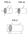
- a fracture type due to the crack generation mentioned above it is found that there is two types. That is to say, as shown in Fig.
- one type is a ring crack 4 in which the honeycomb structural body 1 is broken in the directions at a plane substantially perpendicular to an axial direction of passages 3 defined by partition walls 2. Further, as shown in Fig. 1b, the other type is an end crack 5 in which a crack is generated at one end surface or both end surfaces of the honeycomb structural body 1.
- the honeycomb structural body When the catalyst carrier including the honeycomb structural body is used in the automobile, it is better that the honeycomb structural body has a higher spalling strength mentioned above. This is because the higher spalling strength is an extremely significant characteristic in the case that the honeycomb structural body is exposed to a high temperature exhaust gas as compared with the conventional one or in the case that a temperature of the exhaust gas during a high speed driving becomes higher so as to improve fuel consumption, since it is necessary to arrange the catalyst carrier in the vicinity of the engine according to the severe exhaust gas regulation. Then, if the cracks mentioned above are generated during an actual use due to the low spalling strength, a decrease of exhaust gas purifying performance, a decrease of engine power in accordance with pressure loss increase, and a generation of noise from the exhaust system occur. From the view points mentioned above, even in the honeycomb structural body having an improved exhaust gas purifying performance, it is desired to obtain a honeycomb structural body having higher spalling strength.
- US 4 556 543 recommends that in a honeycomb ceramic body (of unspecified wall thickness) the ratio of the length L and diameter D is in the ratio 0.1 ⁇ L/D ⁇ 0.4.
- An object of the invention is to eliminate the drawbacks mentioned above and to provide a honeycomb structural body having a high spalling strength while maintaining a high exhaust gas purifying performance.
- the invention provides a honeycomb structural body according to claim 1.
- the honeycomb structural body having an excellent spalling characteristic can be obtained by setting a ratio of L/d in a range of 0.8-0.9, where d is a diameter of an inscribed circle of the honeycomb structural body and L is a length thereof. Moreover, it is found that this effect is particularly remarkable in the case that a thickness of the partition wall is smaller than 0.1 mm and the number of the passages is 100 per 1 cm 2 .
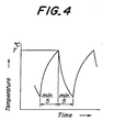
- a honeycomb structural body 1 made of cordierite in which a plurality of passages 3 aligned in its axial direction which are defined by partition walls 2 was prepared.
- a ratio of L/d was varied, where d is a diameter of an inscribed circle of the honeycomb structural body 1 and L is a length of the honeycomb structural body 1.
- a spalling strength was estimated by using an apparatus comprising a burner 11 using propane as a fuel and a stainless can member 12 in which the honeycomb structural body 1 is secured via a heat-resistive ceramic mat.
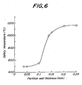
- the estimation test of the spalling strength was performed as follows. At first, the honeycomb structural body 1 secured in the stainless can member 12 is heated by using the burner 11. In this case, the heating operation was performed in such a manner that a gas temperature at a position 10 mm upstream of the honeycomb structural body 1 becomes a predetermined temperature (T°C) after 5 minutes from a start of the heating operation. After that, the honeycomb structural body 1 was cooled for 5 minutes after an end of the heating operation by flowing an air having a room temperature through the honeycomb structural body 1. The above mentioned heating and cooling cycle was repeated 5 times. One heat curve of this cycle is shown in Fig. 4.
- the same estimation test was repeated under such a condition that the temperature T is increased by 25°C with respect to the honeycomb structural body 1 having no cracks. Then, a safety temperature was determined as the temperature T just before a defect such as cracks are generated in the honeycomb structural body 1. Moreover, a gas flow rate during the estimation test was 2.0 Nm 3 /minute when heating and 1.7 Nm 3 /minute when cooling.
- the spalling strength estimation test mentioned above was performed with respect to the cordierite honeycomb structural bodies 1, each having a porosity of 28% and a volume of 1 liter, in which a ratio of L/d is varied, so as to estimate the ratio of L/d.
- the spalling strength estimation test was performed to four series of the honeycomb structural bodies 1, first series having a partition wall thickness of 0.05 mm and a cell density of 100 cm 2 , second series having the partition wall thickness of 0.1 mm and the cell density of 100 cm 2 , third series having the partition wall thickness of 0.1 mm and the cell density of 150 cm 2 , and fourth series having the partition wall thickness of 0.05 mm and the cell density of 200 cm 2 .
- the results are shown in Fig. 5.
- honeycomb structural bodies 1 having a volume of 0.65 liter or 1.3 liter and for the honeycomb structural bodies 1 made of the other material such as alumina, SiC, or SiN having a porosity of 20% or 35%.
- the spalling strength of the honeycomb structural body 1 is varied in response to a variation of the ratio of L/d.
- the safety temperature larger than 700°C in which no drawbacks are detected during actual use, is shown in a range of 0.4-1.3.
- the fracture type it is understood that the ring crack is largely generated when the ratio of L/d is larger than a point showing the largest safety temperature in Fig. 5 and the end crack is largely generated when the ratio of L/d is smaller than the point mentioned above.
- the spalling strength is gradually larger from the L/d range of 0.6-1.1 to the L/d range of 0.7-1.0 as compared with that of the L/d range of 0.4-1.3, and is largest in the L/d range of 0.8-0.9.
- the spalling strength estimation test mentioned above was performed with respect to the cordierite honeycomb structural bodies 1, each having a porosity of 28%, a volume of 1 liter, a cell density of 100 cm 2 , and a ratio of L/d of 1.4, in which the partition wall thickness is varied, so as to estimate the partition wall thickness.
- the results are shown in Fig. 6. From the results shown in Fig. 6, it is understood that the spalling strength is decreased in response to a decrease of the partition wall thickness. Moreover, it is understood that the spalling strength is decreased remarkably when the partition wall thickness is smaller than 0.1 mm. Therefore, it is understood that the present invention having an object of spalling strength improvement can be preferably applied if the honeycomb structural body has the partition wall thickness of smaller than 0.1 mm.
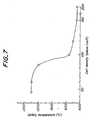
- the spalling strength estimation test mentioned above was performed with respect to the cordierite honeycomb structural bodies 1 having a porosity of 28%, a volume of 1 liter, a partition wall thickness of 0.1 mm, and a ratio of L/d of 1.4, in which the cell density is varied, so as to estimate the cell density.
- the results are shown in Fig. 7. From the results shown in Fig. 7, it is understood that the spalling strength is decreased in response to an increase of the cell density. Moreover, it is understood that the spalling strength is decreased remarkably when the cell density is larger than 100 cm 2 . Therefore, it is understood that the present invention having an object of spalling strength improvement can be preferably applied if the honeycomb structural body has the cell density of larger than 100 cm 2 .
- the honeycomb structural body has the partition wall thickness of smaller than 0.1 mm and the number of passages of larger than 100 per 1 cm 2 .
Landscapes
- Chemical & Material Sciences (AREA)
- Engineering & Computer Science (AREA)
- Chemical Kinetics & Catalysis (AREA)
- Ceramic Engineering (AREA)
- Combustion & Propulsion (AREA)
- Toxicology (AREA)
- Health & Medical Sciences (AREA)
- Mechanical Engineering (AREA)
- General Engineering & Computer Science (AREA)
- Catalysts (AREA)
- Exhaust Gas Treatment By Means Of Catalyst (AREA)
- Filtering Of Dispersed Particles In Gases (AREA)
- Exhaust Gas After Treatment (AREA)
- Porous Artificial Stone Or Porous Ceramic Products (AREA)
- Laminated Bodies (AREA)
Description
- The present invention relates to a honeycomb structural body especially used as a catalyst carrier in an exhaust gas purifying apparatus of a firing apparatus such as a boiler or a combustion apparatus such as an internal combustion engine.
- As the catalyst carrier of the exhaust gas purifying apparatus, the honeycomb structural body has been used. Generally, just after the automobile engine starts, i.e. in a so-called "cold start" state, in which a temperature of the exhaust gas from an exhaust gas generation source is low, it is required to increase a temperature ascending rate of the catalyst in the exhaust gas purifying apparatus so as to activate the exhaust gas purifying function as soon as possible. In order to achieve this requirement, a technique, such that a thermal capacity of the catalyst is made smaller and thus a temperature ascending rate is made faster by forming a partition wall of the honeycomb structural body thinner to an order of 0.15 mm or 0.1 mm, is disclosed in Japanese Patent Laid-Open Publication No. JP-A-7-39761.
- Moreover, in order to further improve the exhaust gas purifying performance, a technique, such that a geometric surface area of the honeycomb structural body is increased i.e. the number of passages per unit area on a surface thereof perpendicular to a passage extending direction (hereinafter, sometimes called as cell density) is increased, is disclosed in papers of No. 960560 and No. 960261 of SAE (Society of Automotive Engineers) in United States.
- During the discussion of the above mentioned prior arts, the following result is found. That is to say, in order to obtain an excellent exhaust gas purifying performance of the catalyst carrier including a ceramic honeycomb structural body, if the partition wall is formed extremely thinner to an order of smaller than 0.1 mm, and if the cell density is increased to an order of larger than 100 pieces per 1 cm2, a spalling strength of the honeycomb structural body indicating a thermal shock resistivity is largely decreased only when a ratio of L/d, wherein d is a diameter of the honeycomb structural body and L is a length thereof, exists in a certain range.
- The spalling strength mentioned above is estimated as follows. At first, the honeycomb structural body is heated by an electric furnace or a burner using combustion gas and then cooled. Then, whether or not a defect of the honeycomb structural body such as cracks is generated is observed. In this case, the spalling strength is estimated by a safety temperature obtained as the highest temperature at which the honeycomb structural body shows no defect. The spalling strength using the electric furnace is defined by automotive standard M505-87 issued by Society of Automative Engineers of Japan, Inc. Moreover, as a fracture type due to the crack generation mentioned above, it is found that there is two types. That is to say, as shown in Fig. 1a, one type is a
ring crack 4 in which the honeycomb structural body 1 is broken in the directions at a plane substantially perpendicular to an axial direction ofpassages 3 defined bypartition walls 2. Further, as shown in Fig. 1b, the other type is anend crack 5 in which a crack is generated at one end surface or both end surfaces of the honeycomb structural body 1. - When the catalyst carrier including the honeycomb structural body is used in the automobile, it is better that the honeycomb structural body has a higher spalling strength mentioned above. This is because the higher spalling strength is an extremely significant characteristic in the case that the honeycomb structural body is exposed to a high temperature exhaust gas as compared with the conventional one or in the case that a temperature of the exhaust gas during a high speed driving becomes higher so as to improve fuel consumption, since it is necessary to arrange the catalyst carrier in the vicinity of the engine according to the severe exhaust gas regulation. Then, if the cracks mentioned above are generated during an actual use due to the low spalling strength, a decrease of exhaust gas purifying performance, a decrease of engine power in accordance with pressure loss increase, and a generation of noise from the exhaust system occur. From the view points mentioned above, even in the honeycomb structural body having an improved exhaust gas purifying performance, it is desired to obtain a honeycomb structural body having higher spalling strength.
- US 4 556 543 recommends that in a honeycomb ceramic body (of unspecified wall thickness) the ratio of the length L and diameter D is in the ratio 0.1 ≤ L/D ≤ 0.4.
- An object of the invention is to eliminate the drawbacks mentioned above and to provide a honeycomb structural body having a high spalling strength while maintaining a high exhaust gas purifying performance.
- Accordingly the invention provides a honeycomb structural body according to claim 1.
- It is found that the honeycomb structural body having an excellent spalling characteristic can be obtained by setting a ratio of L/d in a range of 0.8-0.9, where d is a diameter of an inscribed circle of the honeycomb structural body and L is a length thereof. Moreover, it is found that this effect is particularly remarkable in the case that a thickness of the partition wall is smaller than 0.1 mm and the number of the passages is 100 per 1 cm2.
-
- Figs. 1a and 1b are schematic views for explaining a fracture type of a honeycomb structural body under an estimation test of a spalling strength;
- Fig. 2 is a schematic view showing a shape of the honeycomb structural body used in the embodiment according to the invention;
- Fig. 3 is a schematic view illustrating a construction of an apparatus used for the estimation test of the spalling strength according to the invention;
- Fig. 4 is a graph depicting one embodiment of a heat curve in the estimation test of the spalling strength according to the invention;
- Fig. 5 is a graph showing a relation between a safety temperature and a ratio of L/d of the honeycomb structural body according to the invention;
- Fig. 6 is a graph illustrating a relation between the safety temperature and a thickness of the partition wall of the honeycomb structural body; and
- Fig. 7 is a graph depicting a relation between the safety temperature and a cell density of the honeycomb structural body.
-
- Hereinafter, the present invention will be explained according to actual experiments. At first, as shown in Fig. 2, a honeycomb structural body 1 made of cordierite in which a plurality of
passages 3 aligned in its axial direction which are defined bypartition walls 2 was prepared. In this case, a ratio of L/d was varied, where d is a diameter of an inscribed circle of the honeycomb structural body 1 and L is a length of the honeycomb structural body 1. Then, as shown in Fig. 3, a spalling strength was estimated by using an apparatus comprising a burner 11 using propane as a fuel and a stainless can member 12 in which the honeycomb structural body 1 is secured via a heat-resistive ceramic mat. - The estimation test of the spalling strength was performed as follows. At first, the honeycomb structural body 1 secured in the stainless can member 12 is heated by using the burner 11. In this case, the heating operation was performed in such a manner that a gas temperature at a position 10 mm upstream of the honeycomb structural body 1 becomes a predetermined temperature (T°C) after 5 minutes from a start of the heating operation. After that, the honeycomb structural body 1 was cooled for 5 minutes after an end of the heating operation by flowing an air having a room temperature through the honeycomb structural body 1. The above mentioned heating and cooling cycle was repeated 5 times. One heat curve of this cycle is shown in Fig. 4. After that, the same estimation test was repeated under such a condition that the temperature T is increased by 25°C with respect to the honeycomb structural body 1 having no cracks. Then, a safety temperature was determined as the temperature T just before a defect such as cracks are generated in the honeycomb structural body 1. Moreover, a gas flow rate during the estimation test was 2.0 Nm3/minute when heating and 1.7 Nm3/minute when cooling.
- Hereinafter, the results of the estimation test will be explained.
- At first, the spalling strength estimation test mentioned above was performed with respect to the cordierite honeycomb structural bodies 1, each having a porosity of 28% and a volume of 1 liter, in which a ratio of L/d is varied, so as to estimate the ratio of L/d. In this case, the spalling strength estimation test was performed to four series of the honeycomb structural bodies 1, first series having a partition wall thickness of 0.05 mm and a cell density of 100 cm2, second series having the partition wall thickness of 0.1 mm and the cell density of 100 cm2, third series having the partition wall thickness of 0.1 mm and the cell density of 150 cm2, and fourth series having the partition wall thickness of 0.05 mm and the cell density of 200 cm2. The results are shown in Fig. 5. Moreover, the substantially same results as those mentioned above were obtained for the honeycomb structural bodies 1 having a volume of 0.65 liter or 1.3 liter and for the honeycomb structural bodies 1 made of the other material such as alumina, SiC, or SiN having a porosity of 20% or 35%.
- From the results shown in Fig. 5, it is understood that the spalling strength of the honeycomb structural body 1 is varied in response to a variation of the ratio of L/d. Moreover, it is understood that the safety temperature larger than 700°C, in which no drawbacks are detected during actual use, is shown in a range of 0.4-1.3. Further, as the fracture type, it is understood that the ring crack is largely generated when the ratio of L/d is larger than a point showing the largest safety temperature in Fig. 5 and the end crack is largely generated when the ratio of L/d is smaller than the point mentioned above. Furthermore, it is understood that the spalling strength is gradually larger from the L/d range of 0.6-1.1 to the L/d range of 0.7-1.0 as compared with that of the L/d range of 0.4-1.3, and is largest in the L/d range of 0.8-0.9.
- Then, the spalling strength estimation test mentioned above was performed with respect to the cordierite honeycomb structural bodies 1, each having a porosity of 28%, a volume of 1 liter, a cell density of 100 cm2, and a ratio of L/d of 1.4, in which the partition wall thickness is varied, so as to estimate the partition wall thickness. The results are shown in Fig. 6. From the results shown in Fig. 6, it is understood that the spalling strength is decreased in response to a decrease of the partition wall thickness. Moreover, it is understood that the spalling strength is decreased remarkably when the partition wall thickness is smaller than 0.1 mm. Therefore, it is understood that the present invention having an object of spalling strength improvement can be preferably applied if the honeycomb structural body has the partition wall thickness of smaller than 0.1 mm.
- Then, the spalling strength estimation test mentioned above was performed with respect to the cordierite honeycomb structural bodies 1 having a porosity of 28%, a volume of 1 liter, a partition wall thickness of 0.1 mm, and a ratio of L/d of 1.4, in which the cell density is varied, so as to estimate the cell density. The results are shown in Fig. 7. From the results shown in Fig. 7, it is understood that the spalling strength is decreased in response to an increase of the cell density. Moreover, it is understood that the spalling strength is decreased remarkably when the cell density is larger than 100 cm2. Therefore, it is understood that the present invention having an object of spalling strength improvement can be preferably applied if the honeycomb structural body has the cell density of larger than 100 cm2.
- As clearly understood from the above explanation, according to the invention, since a ratio of L/d is set in a range of 0.8-0.9, where d is a diameter of an inscribed circle of the honeycomb structural body and L is a length thereof, the honeycomb structural body having an excellent spalling characteristic can be obtained.
- Particularly, this effect is remarkable if the honeycomb structural body has the partition wall thickness of smaller than 0.1 mm and the number of passages of larger than 100 per 1 cm2.
Claims (3)
- A honeycomb structural body comprising a plurality of passages aligned in its axial direction which are defined by partition walls, wherein the honeycomb structural body is formed by a ceramic material or materials selected from cordierite, alumina, SiC and SiN, and the ratio L/d is in a range of 0.8-0.9, where d is the diameter of an inscribed circle of the periphery of the honeycomb structural body on a plane perpendicular to its axial direction, and L is the length along the axial direction of the honeycomb structural body, the thickness of the partition walls being smaller than 0.1mm.
- The honeycomb structural body according to claim 1, wherein the number of passages on a plane perpendicular to the axial direction of the passage is larger than 100 per 1 cm2.
- Use of a honeycomb structural body according to claim 1 for purifying an exhaust gas from an internal combustion engine.
Applications Claiming Priority (3)
| Application Number | Priority Date | Filing Date | Title |
|---|---|---|---|
| JP123032/96 | 1996-05-17 | ||
| JP12303296 | 1996-05-17 | ||
| JP8123032A JPH09299811A (en) | 1996-05-17 | 1996-05-17 | Honeycomb structure |
Publications (3)
| Publication Number | Publication Date |
|---|---|
| EP0807466A2 EP0807466A2 (en) | 1997-11-19 |
| EP0807466A3 EP0807466A3 (en) | 1997-12-29 |
| EP0807466B1 true EP0807466B1 (en) | 2001-10-17 |
Family
ID=14850532
Family Applications (1)
| Application Number | Title | Priority Date | Filing Date |
|---|---|---|---|
| EP97303329A Expired - Lifetime EP0807466B1 (en) | 1996-05-17 | 1997-05-16 | Ceramic honeycomb structural body |
Country Status (5)
| Country | Link |
|---|---|
| US (1) | US5895700A (en) |
| EP (1) | EP0807466B1 (en) |
| JP (1) | JPH09299811A (en) |
| CA (1) | CA2205682C (en) |
| DE (1) | DE69707347T2 (en) |
Families Citing this family (23)
| Publication number | Priority date | Publication date | Assignee | Title |
|---|---|---|---|---|
| JP3394449B2 (en) | 1998-06-18 | 2003-04-07 | 日本碍子株式会社 | Thin-walled honeycomb structure and method of reinforcing the same |
| JP2000225340A (en) * | 1998-11-30 | 2000-08-15 | Denso Corp | Honeycomb structure |
| JP2000237602A (en) * | 1998-12-21 | 2000-09-05 | Denso Corp | Catalyst for cleaning exhaust gas of internal combustion engine |
| DE19921263A1 (en) * | 1999-05-07 | 2000-11-16 | Emitec Emissionstechnologie | Internal combustion engine with a small-volume catalyst |
| JP3390698B2 (en) * | 1999-05-31 | 2003-03-24 | 日本碍子株式会社 | Canning structure |
| JP3553424B2 (en) * | 1999-06-22 | 2004-08-11 | 日本碍子株式会社 | Ceramic honeycomb structure, ceramic honeycomb catalyst carrier, and ceramic honeycomb catalytic converter using the same |
| WO2002090735A1 (en) * | 2001-05-02 | 2002-11-14 | Nissan Motor Co., Ltd. | Exhaust gas purification apparatus |
| US7541085B2 (en) * | 2005-07-14 | 2009-06-02 | Burdon Robert L J | Flexible construction element with large bonding surface area and method of manufacture |
| US8609581B2 (en) * | 2005-08-31 | 2013-12-17 | Ngk Insulators, Ltd. | Honeycomb structure and honeycomb catalytic body |
| US7754160B2 (en) * | 2005-08-31 | 2010-07-13 | Ngk Insulators | Honeycomb catalytic body and process for manufacturing honeycomb catalytic body |
| KR100680383B1 (en) * | 2005-10-13 | 2007-02-08 | 현대자동차주식회사 | Mold production method for catalyst carrier |
| CN101389392B (en) | 2006-08-30 | 2011-04-13 | 日立金属株式会社 | Ceramic honeycomb filter |
| JP4402732B1 (en) * | 2008-07-16 | 2010-01-20 | 東京窯業株式会社 | Honeycomb structure |
| JP5313732B2 (en) * | 2009-03-17 | 2013-10-09 | 日本碍子株式会社 | Exhaust gas generator, exhaust gas generation method, and ceramic structure evaluation apparatus |
| JP5261244B2 (en) * | 2009-03-25 | 2013-08-14 | 日本碍子株式会社 | Reactor |
| JP5805039B2 (en) | 2012-09-25 | 2015-11-04 | 日本碍子株式会社 | Honeycomb structure |
| JP6068274B2 (en) | 2013-06-11 | 2017-01-25 | 日本碍子株式会社 | Honeycomb structure |
| JP6059181B2 (en) | 2013-06-11 | 2017-01-11 | 日本碍子株式会社 | Honeycomb structure |
| JP6742779B2 (en) * | 2016-03-30 | 2020-08-19 | 日本碍子株式会社 | Reductant injection device and exhaust gas treatment device |
| JP2019058875A (en) | 2017-09-27 | 2019-04-18 | イビデン株式会社 | Honeycomb catalyst |
| JP2019058876A (en) | 2017-09-27 | 2019-04-18 | イビデン株式会社 | Honeycomb catalyst |
| JP6698602B2 (en) | 2017-09-27 | 2020-05-27 | イビデン株式会社 | Honeycomb catalyst for exhaust gas purification |
| JP6684257B2 (en) | 2017-09-27 | 2020-04-22 | イビデン株式会社 | Honeycomb catalyst for exhaust gas purification |
Family Cites Families (23)
| Publication number | Priority date | Publication date | Assignee | Title |
|---|---|---|---|---|
| US3181928A (en) * | 1960-01-26 | 1965-05-04 | Socony Mobil Oil Co Inc | Process for purifying gases |
| US3562178A (en) * | 1968-01-02 | 1971-02-09 | Phillips Petroleum Co | Complexes of v or n or nb containing no with organoaluminums as olefin reaction catalysts |
| FR2116638A5 (en) * | 1970-12-01 | 1972-07-21 | Thomson Houston Hotchkis | |
| US3939103A (en) * | 1970-12-01 | 1976-02-17 | Compagnie Francaise Thomson Houston-Hotchkiss Brandt | Catalytic product for the oxidative destruction of gaseous organic compounds and method for their preparation |
| US3873350A (en) * | 1973-02-20 | 1975-03-25 | Corning Glass Works | Method of coating honeycombed substrates |
| US3885977A (en) * | 1973-11-05 | 1975-05-27 | Corning Glass Works | Anisotropic cordierite monolith |
| US3985683A (en) * | 1973-11-24 | 1976-10-12 | Hoechst Aktiengesellschaft | Catalyst for reducing the toxic contaminants of combustion engine exhaust gas |
| US4042738A (en) * | 1975-07-28 | 1977-08-16 | Corning Glass Works | Honeycomb structure with high thermal shock resistance |
| JPS5726220A (en) * | 1980-07-24 | 1982-02-12 | Ngk Insulators Ltd | Thermal shock resisting ceramic honeycomb-type catalyzer converter |
| JPS5939346A (en) * | 1982-08-27 | 1984-03-03 | Kiyataraa Kogyo Kk | Preparation of ceramic honeycomb type catalyst carrier |
| DE3522637C1 (en) * | 1985-06-25 | 1986-10-02 | Friedrich Prof. Dr.rer.nat. 2000 Hamburg Steinbach | Catalyst for removing nitrogen oxides, carbon monoxide and / or residual hydrocarbons from exhaust gases |
| JPS6249454A (en) * | 1985-08-28 | 1987-03-04 | Toshiba Corp | Debug supporting circuit for microprogram |
| US4877670A (en) * | 1985-12-27 | 1989-10-31 | Ngk Insulators, Ltd. | Cordierite honeycomb structural body and method of producing the same |
| JPH0356354Y2 (en) * | 1986-04-08 | 1991-12-18 | ||
| DE3780082T2 (en) * | 1986-04-21 | 1993-01-14 | Kawasaki Steel Co | STAINLESS CHROME-ALUMINUM STEEL WITH HIGH RESISTANCE TO OXYDATION AND PEELING AND CHROME-ALUMINUM STEEL FILMS FOR CATALYST CARRIERS IN CATALYTIC CONVERTERS. |
| DE3917890A1 (en) * | 1989-06-01 | 1990-12-06 | Steinbach Friedrich | SUPPORTED CATALYSTS FOR THE REMOVAL OF NITROGEN OXIDE, CARBON MONOXIDE AND ORGANIC COMPOUNDS FROM EXHAUST GAS |
| DE4040150A1 (en) * | 1990-02-28 | 1991-08-29 | Degussa | METHOD OF SUPPORTING CERAMIC WAVE BODIES WITH FINE-PARTIAL SOLIDS |
| JP2801950B2 (en) * | 1990-04-12 | 1998-09-21 | 日本碍子株式会社 | Method of firing metal powder honeycomb monolith structure |
| JP2931362B2 (en) * | 1990-04-12 | 1999-08-09 | 日本碍子株式会社 | Resistance control type heater and catalytic converter |
| JP2843426B2 (en) * | 1990-07-04 | 1999-01-06 | 日本碍子株式会社 | How to operate the catalytic converter |
| JPH0470053A (en) * | 1990-07-09 | 1992-03-05 | Mitsubishi Electric Corp | Close-contact image sensor |
| US5296198A (en) * | 1990-11-09 | 1994-03-22 | Ngk Insulators, Ltd. | Heater and catalytic converter |
| EP0492081A1 (en) * | 1990-12-24 | 1992-07-01 | Corning Incorporated | Activated carbon structures |
-
1996
- 1996-05-17 JP JP8123032A patent/JPH09299811A/en active Pending
-
1997
- 1997-05-16 EP EP97303329A patent/EP0807466B1/en not_active Expired - Lifetime
- 1997-05-16 US US08/857,284 patent/US5895700A/en not_active Expired - Lifetime
- 1997-05-16 DE DE69707347T patent/DE69707347T2/en not_active Expired - Lifetime
- 1997-05-16 CA CA002205682A patent/CA2205682C/en not_active Expired - Fee Related
Also Published As
| Publication number | Publication date |
|---|---|
| DE69707347D1 (en) | 2001-11-22 |
| EP0807466A3 (en) | 1997-12-29 |
| CA2205682C (en) | 2000-12-05 |
| CA2205682A1 (en) | 1997-11-17 |
| DE69707347T2 (en) | 2002-06-27 |
| JPH09299811A (en) | 1997-11-25 |
| EP0807466A2 (en) | 1997-11-19 |
| US5895700A (en) | 1999-04-20 |
Similar Documents
| Publication | Publication Date | Title |
|---|---|---|
| EP0807466B1 (en) | Ceramic honeycomb structural body | |
| US7056365B2 (en) | Honeycomb structure, and honeycomb filter and converter system both using the same | |
| EP0737801B1 (en) | Exhaust gas purifying filter and apparatus utilizing said filter | |
| EP1360991B1 (en) | Ceramic honeycomb structure | |
| US5692373A (en) | Exhaust manifold with integral catalytic converter | |
| US4556543A (en) | Ceramic honeycomb catalytic converters having high thermal shock resistance | |
| US6989048B2 (en) | Particulate filter for purifying exhaust gases of internal combustion engines comprising hot spot ceramic ignitors | |
| AU2002302682B2 (en) | Filtering body for filtering particles contained in an internal combustion engine exhaust gases | |
| EP1291061A1 (en) | Honeycomb structure and honeycomb filter, and method of producing them | |
| EP1348843A2 (en) | Ceramic honeycomb filter and exhaust gas-cleaning method | |
| EP1997556A1 (en) | Honeycomb catalyst structure | |
| EP0724070A1 (en) | Honeycomb catalytic converter | |
| CA2201090C (en) | Ceramic honeycomb catalyst having excellent thermal shock resistance | |
| EP1482138A1 (en) | Exhaust emission control system, method of calculating pressure loss of filter, and method of manufacturing filter | |
| Cutler et al. | A new high temperature ceramic material for diesel particulate filter applications | |
| JPH0861054A (en) | Exhaust gas purification device manufacturing method | |
| US20020168304A1 (en) | Devices for managing housing expansion in exhaust emission control devices | |
| JP3587270B2 (en) | DPF regeneration system using heater | |
| US20200306741A1 (en) | Honeycomb structure | |
| JP2008043850A (en) | Honeycomb structure | |
| Mizuno et al. | Controlling of heating rates for safe regeneration of ceramic honeycomb diesel particulate filter | |
| JP2000145429A (en) | Exhaust gas flow restricting member for an exhaust gas purifier | |
| JP2570317B2 (en) | Particle collection and purification equipment | |
| JP5811394B2 (en) | Diesel particulate filter | |
| ZA200200839B (en) | Honeycomb structure and honeycomb filter, and method of producing them. |
Legal Events
| Date | Code | Title | Description |
|---|---|---|---|
| PUAI | Public reference made under article 153(3) epc to a published international application that has entered the european phase |
Free format text: ORIGINAL CODE: 0009012 |
|
| PUAL | Search report despatched |
Free format text: ORIGINAL CODE: 0009013 |
|
| AK | Designated contracting states |
Kind code of ref document: A2 Designated state(s): DE FR GB IT |
|
| AK | Designated contracting states |
Kind code of ref document: A3 Designated state(s): DE FR GB IT |
|
| 17P | Request for examination filed |
Effective date: 19980624 |
|
| 17Q | First examination report despatched |
Effective date: 19981009 |
|
| GRAG | Despatch of communication of intention to grant |
Free format text: ORIGINAL CODE: EPIDOS AGRA |
|
| RTI1 | Title (correction) |
Free format text: CERAMIC HONEYCOMB STRUCTURAL BODY |
|
| GRAG | Despatch of communication of intention to grant |
Free format text: ORIGINAL CODE: EPIDOS AGRA |
|
| GRAH | Despatch of communication of intention to grant a patent |
Free format text: ORIGINAL CODE: EPIDOS IGRA |
|
| GRAH | Despatch of communication of intention to grant a patent |
Free format text: ORIGINAL CODE: EPIDOS IGRA |
|
| GRAA | (expected) grant |
Free format text: ORIGINAL CODE: 0009210 |
|
| AK | Designated contracting states |
Kind code of ref document: B1 Designated state(s): DE FR GB IT |
|
| REF | Corresponds to: |
Ref document number: 69707347 Country of ref document: DE Date of ref document: 20011122 |
|
| REG | Reference to a national code |
Ref country code: GB Ref legal event code: IF02 |
|
| ET | Fr: translation filed | ||
| PLBE | No opposition filed within time limit |
Free format text: ORIGINAL CODE: 0009261 |
|
| STAA | Information on the status of an ep patent application or granted ep patent |
Free format text: STATUS: NO OPPOSITION FILED WITHIN TIME LIMIT |
|
| 26N | No opposition filed | ||
| PGFP | Annual fee paid to national office [announced via postgrant information from national office to epo] |
Ref country code: GB Payment date: 20040506 Year of fee payment: 8 |
|
| PG25 | Lapsed in a contracting state [announced via postgrant information from national office to epo] |
Ref country code: IT Free format text: LAPSE BECAUSE OF NON-PAYMENT OF DUE FEES;WARNING: LAPSES OF ITALIAN PATENTS WITH EFFECTIVE DATE BEFORE 2007 MAY HAVE OCCURRED AT ANY TIME BEFORE 2007. THE CORRECT EFFECTIVE DATE MAY BE DIFFERENT FROM THE ONE RECORDED. Effective date: 20050516 Ref country code: GB Free format text: LAPSE BECAUSE OF NON-PAYMENT OF DUE FEES Effective date: 20050516 |
|
| GBPC | Gb: european patent ceased through non-payment of renewal fee |
Effective date: 20050516 |
|
| REG | Reference to a national code |
Ref country code: FR Ref legal event code: PLFP Year of fee payment: 20 |
|
| PGFP | Annual fee paid to national office [announced via postgrant information from national office to epo] |
Ref country code: DE Payment date: 20160510 Year of fee payment: 20 |
|
| PGFP | Annual fee paid to national office [announced via postgrant information from national office to epo] |
Ref country code: FR Payment date: 20160412 Year of fee payment: 20 |
|
| REG | Reference to a national code |
Ref country code: DE Ref legal event code: R071 Ref document number: 69707347 Country of ref document: DE |