EP0807236B1 - Metallic monolith and plates for the assembly thereof - Google Patents
Metallic monolith and plates for the assembly thereof Download PDFInfo
- Publication number
- EP0807236B1 EP0807236B1 EP96903686A EP96903686A EP0807236B1 EP 0807236 B1 EP0807236 B1 EP 0807236B1 EP 96903686 A EP96903686 A EP 96903686A EP 96903686 A EP96903686 A EP 96903686A EP 0807236 B1 EP0807236 B1 EP 0807236B1
- Authority
- EP
- European Patent Office
- Prior art keywords
- plate
- riser
- monolith
- width
- baffle
- Prior art date
- Legal status (The legal status is an assumption and is not a legal conclusion. Google has not performed a legal analysis and makes no representation as to the accuracy of the status listed.)
- Expired - Lifetime
Links
Images


Classifications
-
- B—PERFORMING OPERATIONS; TRANSPORTING
- B01—PHYSICAL OR CHEMICAL PROCESSES OR APPARATUS IN GENERAL
- B01J—CHEMICAL OR PHYSICAL PROCESSES, e.g. CATALYSIS OR COLLOID CHEMISTRY; THEIR RELEVANT APPARATUS
- B01J19/00—Chemical, physical or physico-chemical processes in general; Their relevant apparatus
- B01J19/24—Stationary reactors without moving elements inside
- B01J19/248—Reactors comprising multiple separated flow channels
- B01J19/249—Plate-type reactors
-
- F—MECHANICAL ENGINEERING; LIGHTING; HEATING; WEAPONS; BLASTING
- F01—MACHINES OR ENGINES IN GENERAL; ENGINE PLANTS IN GENERAL; STEAM ENGINES
- F01N—GAS-FLOW SILENCERS OR EXHAUST APPARATUS FOR MACHINES OR ENGINES IN GENERAL; GAS-FLOW SILENCERS OR EXHAUST APPARATUS FOR INTERNAL-COMBUSTION ENGINES
- F01N3/00—Exhaust or silencing apparatus having means for purifying, rendering innocuous, or otherwise treating exhaust
- F01N3/08—Exhaust or silencing apparatus having means for purifying, rendering innocuous, or otherwise treating exhaust for rendering innocuous
- F01N3/10—Exhaust or silencing apparatus having means for purifying, rendering innocuous, or otherwise treating exhaust for rendering innocuous by thermal or catalytic conversion of noxious components of exhaust
- F01N3/24—Exhaust or silencing apparatus having means for purifying, rendering innocuous, or otherwise treating exhaust for rendering innocuous by thermal or catalytic conversion of noxious components of exhaust characterised by constructional aspects of converting apparatus
- F01N3/28—Construction of catalytic reactors
- F01N3/2803—Construction of catalytic reactors characterised by structure, by material or by manufacturing of catalyst support
- F01N3/2807—Metal other than sintered metal
- F01N3/281—Metallic honeycomb monoliths made of stacked or rolled sheets, foils or plates
- F01N3/2817—Metallic honeycomb monoliths made of stacked or rolled sheets, foils or plates only with non-corrugated sheets, plates or foils
-
- F—MECHANICAL ENGINEERING; LIGHTING; HEATING; WEAPONS; BLASTING
- F28—HEAT EXCHANGE IN GENERAL
- F28D—HEAT-EXCHANGE APPARATUS, NOT PROVIDED FOR IN ANOTHER SUBCLASS, IN WHICH THE HEAT-EXCHANGE MEDIA DO NOT COME INTO DIRECT CONTACT
- F28D9/00—Heat-exchange apparatus having stationary plate-like or laminated conduit assemblies for both heat-exchange media, the media being in contact with different sides of a conduit wall
- F28D9/0031—Heat-exchange apparatus having stationary plate-like or laminated conduit assemblies for both heat-exchange media, the media being in contact with different sides of a conduit wall the conduits for one heat-exchange medium being formed by paired plates touching each other
- F28D9/0037—Heat-exchange apparatus having stationary plate-like or laminated conduit assemblies for both heat-exchange media, the media being in contact with different sides of a conduit wall the conduits for one heat-exchange medium being formed by paired plates touching each other the conduits for the other heat-exchange medium also being formed by paired plates touching each other
-
- B—PERFORMING OPERATIONS; TRANSPORTING
- B01—PHYSICAL OR CHEMICAL PROCESSES OR APPARATUS IN GENERAL
- B01J—CHEMICAL OR PHYSICAL PROCESSES, e.g. CATALYSIS OR COLLOID CHEMISTRY; THEIR RELEVANT APPARATUS
- B01J2219/00—Chemical, physical or physico-chemical processes in general; Their relevant apparatus
- B01J2219/24—Stationary reactors without moving elements inside
- B01J2219/2401—Reactors comprising multiple separate flow channels
- B01J2219/245—Plate-type reactors
- B01J2219/2451—Geometry of the reactor
- B01J2219/2453—Plates arranged in parallel
-
- B—PERFORMING OPERATIONS; TRANSPORTING
- B01—PHYSICAL OR CHEMICAL PROCESSES OR APPARATUS IN GENERAL
- B01J—CHEMICAL OR PHYSICAL PROCESSES, e.g. CATALYSIS OR COLLOID CHEMISTRY; THEIR RELEVANT APPARATUS
- B01J2219/00—Chemical, physical or physico-chemical processes in general; Their relevant apparatus
- B01J2219/24—Stationary reactors without moving elements inside
- B01J2219/2401—Reactors comprising multiple separate flow channels
- B01J2219/245—Plate-type reactors
- B01J2219/2474—Mixing means, e.g. fins or baffles attached to the plates
-
- B—PERFORMING OPERATIONS; TRANSPORTING
- B01—PHYSICAL OR CHEMICAL PROCESSES OR APPARATUS IN GENERAL
- B01J—CHEMICAL OR PHYSICAL PROCESSES, e.g. CATALYSIS OR COLLOID CHEMISTRY; THEIR RELEVANT APPARATUS
- B01J2219/00—Chemical, physical or physico-chemical processes in general; Their relevant apparatus
- B01J2219/24—Stationary reactors without moving elements inside
- B01J2219/2401—Reactors comprising multiple separate flow channels
- B01J2219/245—Plate-type reactors
- B01J2219/2476—Construction materials
- B01J2219/2477—Construction materials of the catalysts
- B01J2219/2479—Catalysts coated on the surface of plates or inserts
-
- B—PERFORMING OPERATIONS; TRANSPORTING
- B01—PHYSICAL OR CHEMICAL PROCESSES OR APPARATUS IN GENERAL
- B01J—CHEMICAL OR PHYSICAL PROCESSES, e.g. CATALYSIS OR COLLOID CHEMISTRY; THEIR RELEVANT APPARATUS
- B01J2219/00—Chemical, physical or physico-chemical processes in general; Their relevant apparatus
- B01J2219/24—Stationary reactors without moving elements inside
- B01J2219/2401—Reactors comprising multiple separate flow channels
- B01J2219/245—Plate-type reactors
- B01J2219/2491—Other constructional details
- B01J2219/2492—Assembling means
- B01J2219/2493—Means for assembling plates together, e.g. sealing means, screws, bolts
-
- B—PERFORMING OPERATIONS; TRANSPORTING
- B01—PHYSICAL OR CHEMICAL PROCESSES OR APPARATUS IN GENERAL
- B01J—CHEMICAL OR PHYSICAL PROCESSES, e.g. CATALYSIS OR COLLOID CHEMISTRY; THEIR RELEVANT APPARATUS
- B01J2219/00—Chemical, physical or physico-chemical processes in general; Their relevant apparatus
- B01J2219/24—Stationary reactors without moving elements inside
- B01J2219/2401—Reactors comprising multiple separate flow channels
- B01J2219/245—Plate-type reactors
- B01J2219/2491—Other constructional details
- B01J2219/2497—Size aspects, i.e. concrete sizes are being mentioned in the classified document
-
- B—PERFORMING OPERATIONS; TRANSPORTING
- B01—PHYSICAL OR CHEMICAL PROCESSES OR APPARATUS IN GENERAL
- B01J—CHEMICAL OR PHYSICAL PROCESSES, e.g. CATALYSIS OR COLLOID CHEMISTRY; THEIR RELEVANT APPARATUS
- B01J35/00—Catalysts, in general, characterised by their form or physical properties
- B01J35/50—Catalysts, in general, characterised by their form or physical properties characterised by their shape or configuration
- B01J35/56—Foraminous structures having flow-through passages or channels, e.g. grids or three-dimensional [3D] monoliths
Definitions
- This invention relates to the construction of metallic heat exchangers and monoliths, and more particularly to the configuration of plates used for constructing such devices.
- Metallic articles comprising a plurality of plenums have long been used as heat exchangers to transfer heat between gas streams.
- a variety of methods are known for constructing such heat exchangers, which in general comprise at least a first plurality of conduits or ducts through which a first gas stream may be flowed.
- the first plurality of ducts provided by heat exchange tubes runs through the cross-sectional flow area of at least one larger duct, so that a second gas stream passing through the larger duct flows around and in contact with the heat exchange tubes, so that heat may be exchanged between the first and second gas streams through the metallic tubes.
- US-A-5,072,790 discloses a heat exchanger core that is formed by a plurality of stacked plates which are rectangular.
- the core is constructed by defining walls extending at right angles from the side edges of one of the plates and an inturned flange, at the extremity of each wall, co-operative with a slot formed on the next adjacent plate.
- the core further includes a separate corner member, co-operative with the plates.
- the present invention provides, as claimed in claim 1 hereinafter, plates for the assembly of a monolith suitable for use as a heat exchanger or as a carrier for a catalyst member, and monoliths comprising plates according to the present invention.
- the present invention provides a plate used in the assembly of a monolith, the plate comprising a central baffle portion having two sides and two ends, a support flange attached to each end of the first plate for supporting a succeeding plate in parallel, spaced relation to the plate, and anchor flanges attached to each end of the plate for closing off the corners of a monolith comprising the plate.
- each support flange may comprise a riser portion having two sides and being attached on one side to an end of the baffle portion, and a landing portion attached to the other side of the riser portion.
- each anchor flange may extend from the baffle portion for a length equal to at least twice the width of the riser portion.
- each anchor flange may comprise a leg portion and a riser-engaging tab extending from the leg portion in a direction perpendicular to the side of the plate for engaging the riser portion of a preceding plate support flange on which the first plate may be mounted.
- the plate may further comprise a sub-riser-engaging tab attached to the leg portion and extending therefrom, for engaging the riser portion of the support flange of a second preceding plate, on which the first preceding plate is mounted.
- a bendable first plate used in the assembly of a monolith may comprise, when in its flat configuration, a generally rectangular central baffle portion having a width defined by a pair of generally straight, parallel side edges and being mounted on the ends by a flange border.
- the riser portion has two sides and two ends and is attached on one side to the baffle portion at the flange border, and is bendable to a substantially perpendicular relationship with the baffle portion.
- the landing portion is attached to the other side of the riser portion and is bendable to be substantially parallel to the baffle portion, for supporting a succeeding plate configured like the first plate.
- the length of the riser portion is less than the width of the baffle portion.
- the riser portion may be disposed centrally between the side edges of the baffle portion,
- a pair of anchor flanges is attached to each end of the baffle portion, beside each end of the riser portions.
- Each anchor flange is contiguous with the support flange, and is bendable to a substantially perpendicular relationship with the baffle portion in a direction opposite to that of the riser portion.
- the anchor flange has a width equal to about one-half the difference between the end-to-end length of the riser portion and the width of the baffle portion, and so when bent downward can at least partially close off the corner of a monolith comprising the plate.
- the anchor flange may comprise a leg portion for at least partially closing off the corner of a monolith comprising the plate and may optionally further comprise a riser-engaging tab.
- the riser-engaging tab is attached to and extends from the leg portion away from the riser portion, and has a width not greater than the width of the riser portion.
- the riser-engaging tab has a length greater than the width of the leg portion, for engaging the riser portion of a preceding plate configured like the first plate, on which the first plate is mounted.
- the width W of the baffle portion may exceed the length R of each riser portion by an amount designated 2T, and the width of each leg portion may equal T. Further, the width W of the baffle portion may exceed the length D of the baffle portion by an amount designated 2S, and the width of each riser portion may equal S.
- the leg portion may have a length greater than twice the width of the riser portion.
- each anchor flange may further comprise a sub-riser-engaging tab connected to and extending from the leg portion towards the landing portion from a point separated from the baffle portion by at least the width of the riser portion.
- the sub-riser-engaging tab may have a width not greater than the width of the riser portion, for engaging the riser portion of a second preceding plate configured like the first, on which a first preceding plate is mounted.
- the invention also provides a monolith comprising at least a first plate, a succeeding plate and a preceding plate, wherein at least the first plate and the succeeding plate comprise plates according to the present invention, and wherein the preceding plate comprises at least a support flange.
- the riser portions of the support flanges are bent at right angles to the baffle portion and the landing portions of the support flanges are bent at right angles to the riser portion to support the succeeding plate in spaced, parallel mounted relation to the first plate.
- the anchor flanges of the succeeding plate are bent at right angles to the baffle portion thereof and towards the first plate.
- the first plate is mounted on the landing portions of the supporting flanges of a preceding plate, and its anchor flanges bent at right angles to its baffle portion.
- the baffle portion and riser portions of the first plate together with the baffle portion of the succeeding plate define a first open-ended gas flow conduit through the monolith
- the baffle portion and riser portions of the preceding plate together with the baffle portion of the first plate define a second, open-ended gas flow conduit through the monolith
- the second gas flow conduit is disposed at right angles to the first gas flow conduit.
- the first plate, the succeeding plate and the preceding plate define corners that are closed off by the anchor flanges of the first plate and the succeeding plate.
- At least the first plate and the succeeding plate may comprise anchor flanges comprising leg portions and riser-engaging tabs attached to the leg portion and extending away from the riser portion.
- the riser-engaging tab has a width not greater than the width of the riser portion of the preceding plate and engages the riser portion of the preceding plate.
- the plates and the monolith may comprise a catalytic material.
- the monolith may comprise high surface area, catalytic material bearing inserts in the conduits.
- the term “upward” is used to indicate the direction in which the riser portion of a support flange is bent out of the plane of the baffle portion of the plate.
- the direction in which an anchor flange is bent is, accordingly, designated “downward”.
- the term “succeeding” is used to indicate a plate disposed “upwardly” of another and the term “preceding” is used to indicate a plate disposed “downwardly” of another.
- the Figures show plates disposed with support flanges bent towards the top of the Figures.
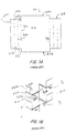
- Plate 810 has a baffle portion 812 which has two sides 814a and 814b and which is bordered by bend lines 816 where support flanges 818 are attached to baffle portion 812. Only one of support flanges 818 will be described in detail, since the two are similarly configured.
- support flange 818 is bent along bend line 816 into a right angle configuration relative to baffle portion 812. Support flange 818 is then divided into three parallel portions, a riser portion 822, a landing portion 824a and an optional fold-over portion 824b by bends at bend lines 826 and 828.
- these bends are alternating right angle bends, so that support flange 818 has, in side view, a zig-zag configuration.
- a plurality of plates configured in this way can be stacked one atop the other in right angle configurations to each other, so that side edges of a second rest on the horizontal landing portion 824a of plate 810, with fold-over portions 824b still in their perpendicular, upright positions, as shown in Figure 1B. Fold-over portions 824b may then be folded over onto the sides of the supported plate to secure the plates together.
- the assembled monolith defines a first plurality of gas flow passages A and a second plurality of gas flow passages B that extend at right angles to passages A.
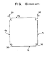
- passages A extend between faces A 1 and A 2 of the monolith, shown in the schematic view of Figure 1C
- passages B extend between faces B 1 and B 2 .
- Figure 1B the completed monolith, in plan view, has a rectangular configuration having notched corners as shown in Figure 1C. The corners are open so that gas flowing into contact with face A will be able to enter gas flow passages B, where a different gas stream may be flowing.
- the corners of the monolith must be closed off by securing angle members, such as members 35, to each corner of the device.
- a heat exchanger monolith may be prepared in accordance with the present invention by assembling a plurality of interlocking plates, each plate being configured like the next.
- the assembled monolith defines two pluralities of open-ended gas flow conduits extending therethrough, the conduits being sequentially arranged and extending alternately at right angles from one to the next.
- the assembled monolith is rectangular in shape, and the first plurality of conduits has open ends at one pair of sides of the monolith, and a second plurality of conduits has open ends at the other sides of the monolith.
- a gas stream may be flowed through the first plurality of conduits in right angle or crossflow relation to a gas stream flowing through the second plurality of conduits.
- the plates are formed from metal having good heat exchange properties, so that heat is easily passed through the plates from gas flowing through one plurality of conduits to gas flowing through the other.
- plates in accordance with the present invention comprise a baffle region bounded by a pair of substantially straight, parallel sides. At the opposite ends of the baffle region, the plate comprises two types of flanges that are bendable out of the plane of the baffle region.
- the first type of flange is a support flange. Support flanges are bendable into a configuration where they can provide landings for a second plate to be held in spaced, parallel relation to the first plate.
- the baffle regions of the two plates and the support flanges of the first plate together define an open-ended conduit through which a gas stream may flow.
- the second plate Since the support flanges on the ends of the first plate engage the sides of the second plate, the second plate is disposed at right angles with respect to the first plate, and its support flanges will extend away from the first plate above the open ends of the first conduit, to support yet another, third, plate in crosswise relation to it and therefore in parallel relation to the first plate.
- the baffle portions of the second and third plates, together with the support flanges of the second plate, define a second open-ended conduit disposed in crosswise relation to the first conduit.
- anchor flanges are bendable at right angles to the baffle portion in a direction opposite to that of the support flanges, and anchor flanges serve at least to close the open corner of the assembled monolith, to eliminate the need for angle members.
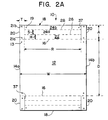
- a plate in accordance with one embodiment of the invention is shown in Figure 2A.
- the plate shown in Figure 2A is symmetric in that the flanges at one end are configured like, and function identically to, those at the other end. Accordingly, the description of the flanges of one end of the plate will apply equally to those at the other end.
- Plate 10 comprises a baffle portion 12 having a pair of substantially straight, parallel sides 14a, 14b, which define the width W of baffle portion 12.
- the ends of baffle portion 12 are defined by bend lines 16, which are separated by a distance D which defines the length of baffle portion 12 and which is shorter than width W by an amount designated 2S.
- W D + 2S.
- a support flange 18 and anchor flanges 20 are attached to baffle portion 12 at bend line 16.
- Support flange 18 comprises a riser portion 22 which is attached to baffle portion 12 along bend line 16 and which has an end-toend length R which is shorter than width W by an amount designated 2T.
- W R + 2T.
- Support flange 18 also comprises a landing portion 24a which is separated from riser portion 22 by bend line 26 and has the same length as riser portion 22.
- Support flange 18 comprises a fold-over portion 24b that is attached to landing portion 24a along bend line 28.
- landing portion 24a can be bent into a plane parallel to that of baffle portion 12 to provide a support surface on which a similary configured plate may be mounted, at a height H above baffle portion 12 indicated in Figure 2B.
- Bend line 28 is disposed at about a distance S from bend line 26.
- Anchor flange 20 is attached to the end of baffle portion 12, beside each end of riser portion 22, and has a width T and extends away from baffle portion 12 for a length A which is at least twice width H of riser portion 22, and preferably greater than twice H.
- Anchor flange 20 is contiguous with support flange 18 along slot 37 which separates them.
- Anchor flange 20 is bendable along bend line 16 so that it is disposed at right angles to, and extends away from, baffle portion 12 in a direction opposite to that of riser portion 22.
- the resulting configuration is shown in Figure 2B.
- a monolith By preparing a plurality of plates as shown in Figure 2B and disposing them one atop the other in alternating 90° relation to one another, a monolith can be assembled.
- One corner of such a monolith is shown in Figure 2C, in which baffle portion 12, one side 14a and anchor flange 20, bend line 28 and a fold-over portion 24b of the plate of Figure 2B are labeled.
- the anchor flanges can be used to seal the corners of the monolith, and thus eliminate the need for the angle members needed with prior art monoliths.
- the length A of the anchor flanges is long enough to permit each anchor flange to overlap the anchor flange of at least one preceding plate, to facilitate attachment of the flanges together.
- the length A of the plates may vary.
- the two uppermost plates of the monolith may be provided with anchor flanges long enough to reach to the bottom of the monolith.
- the remainder of the monolith could be constructed from plates according to the prior art, and the need for angle members would still be obviated.
- plates according to the present invention could be situated periodically within a monolith and may have anchor flanges long enough to extend to the anchor flange of the next plate according to the present invention.
- each plate having anchor flanges of a length greater than 4H could be alternated in pairs with plates according to the prior art, and the anchor flanges could be long enough to close off the corner of the monolith.
- the top two plates would comprise plates in accordance with the present invention
- the next two plates may comprise plates without anchor flanges
- the next two plates would comprise plates in accordance with the present invention, and so on.
- each plate may have anchor flanges long enough to reach the bottom of the monolith.
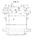
- anchor flange 20 comprises a leg portion 30 and a riser-engaging tab 32 which extends from leg portion 30 away from riser portion 22 for a distance greater than the width of leg portion 30, and is dimensioned and configured to engage the riser portion of a plate that may support plate 10', as will be described below.
- Riser-engaging tab 32 has a width that does not exceed, and is preferably equal to, H.
- riser portion 22 is bent upwards at flange border (bend line 16), at right angles to baffle portion 12, while leg portion 30 is bent downwards at right angles to baffle portion 12.
- Landing portion 24a (not visible in Figure 4A) is bent at right angles to riser portion 22, and away from baffle portion 12, to form a landing on which the side edge of another plate may be placed.
- Foldover portion 24b is folded nearly 180° at bend line 28, so that a slot is formed between fold-over portion 24b and landing portion 24a into which the edge of a plate may be inserted.
- riser-engaging tab 32 will be bent over and around leg portion 30, as shown in Figure 4B.
- Plate 10' folded as in Figure 4B, is shown in Figure 5 mounted on a second plate 110.
- Plate 110 is configured identically to plate 10', and corresponding structures are labelled with corresponding numerals, except that the structures on plate 110 are three digit numbers having the numeral one (1) as the first digit, i.e., plate 10' comprises a baffle portion 12 while plate 110 comprises a baffle portion 112, etc.
- the side 14b of plate 10' (shown in Figures 4A and 4B but not visible in Figure 5) is inserted into a slot formed by fold-over portion 124b and the underlying landing portion of the support flange of plate 110 (not shown).
- Plate 10' may then be secured in the landing portion 124 of plate 110 by crimping, welding, soldering, riveting or any other conventional method, along landing portion 124.
- Landing portion 124 of plate 110 supports plate 10' above plate 110 at a height determined by the width of riser portion 122.
- Riser-engaging tab 32 of plate 10' is bent over and around leg portion 30 as shown in Figure 4B, so that it engages, i.e., lies flat against, riser portion 122 of plate 110. Plates 10' and 110 may then be secured together by crimping, welding, riveting, soldering, etc., riser-engaging tab 32 onto riser portion 122.
- baffle portion 112, riser portions 122 and baffle portion 12 together define a conduit through which gas can flow as indicated by gas flow arrow 34.
- the anchor flange 120 of plate 110 is shown bent downwards at right angles to baffle portion 112, and is partially prepared to engage the riser of a supporting plate (not shown).
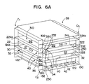
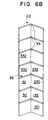
- leg portion of a first plate extends downwards, it is disposed at right angles to the leg portion of the immediately preceding plate. However, if it extends further downward, it will engage the leg portion of the second preceding plate. Thus, the lower end of leg portion 30 could be inserted into a slot between the riser-engaging tab and the leg portion of the second preceding plate (not shown) corresponding to slot 36 formed between the riser-engaging tab 32 and the leg portion 30 of plate 10'. Likewise, the downward extending leg portion of the second succeeding plate 310 to plate 10' can be inserted into slot 36, as shown in Figures 6A and 6B.
- Figure 6A shows a monolith assembled using a plurality of plates as shown in Figure 3 which are interconnected as shown in Figure 5.
- plates 10' and 110 of Figure 5 are disposed in the interior of monolith 38 and their respective baffle portions 12, 112, riser portions 22, 122, fold-over portions 24b, 124b are shown.
- Leg portions 30 of plate 10' are visible in corners C1 or C2 of monolith 38, while a small portion of riser-engaging tab 32 is visible at corner C3.
- riser-engaging tab 32 is seen in dotted outline folded over and around leg portion 30 and in engagement with riser portion 122.
- the monolith so constructed has a first plurality of open-ended gas flow conduits 34 and a second plurality of open-ended gas flow conduits 40 disposed in crosswise relation to first plurality 34.
- the supporting flanges of the top plate will, of course, not be used and may therefore be at least partially cut off from the plate.
- the riser portion of the top plate is retained and is not bent out of the plane of the baffle portion. If they are not removed, the landing portion and the attached fold-over portion can be folded flat against the plate.
- the edges of the top plate are square with the sides of the monolith.
- the anchor flanges of the bottom plate are of no use, and may be removed at the flange border (bend line 16) or may be folded upward in engagement with a succeeding plate.
- Monolith 38 may be mounted in a housing providing convenient inlet and outlet manifolds that will guide a first and second gas stream through the respective pluralities of conduits to achieve heat exchange.
- such a monolith may be coated with catalytic material and used as a catalytic converter.
- monolith 38 may be mounted in a housing having appropriate inlet and outlet manifolds and an appropriate transfer manifold so that the inlet gas enters through conduits 34, then through the transfer conduit and then through conduits 40, and then to the outlet manifold.
- monolith 38 may be coated with a catalytic material effective to treat gaseous components of the gas streams flowing therethrough. This may be accomplished by immersing monolith 38 in a slurry of the catalytic material, and then drying and calcining the monolith to leave a washcoat of catalytic material thereon.
- the plates may be coated with catalytic material before the monolith is assembled.
- the conduits e.g., conduits 34 and 40
- monolith 38 may be used in a particular embodiment as a catalytic heat exchange member capable of converting noxious components of an automotive exhaust gas stream such as NO X , CO and hydrocarbons to innocuous substances such as N 2 , CO 2 and H 2 O.
- the catalytic material comprises a conventional three-way catalyst, which is known in the art to comprise platinum group metals such as Pt, Pd and Rh dispersed on a refractory oxide support material.
- the slurry used to coat the monolith comprises particles of the support material onto which the platinum group metals have been dispersed.
- the catalytic process occurring in one set of gas flow passages can be accelerated by heat exchange with gas flowing through the second set of gas flow passages.
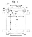
- Plate 410 is generally similar to plate 10' of Figure 4, so the structures thereon are accorded similar indicator numerals, the indicator numerals for plate 410 being preceeded by the number 4.
- plate 410 comprises riser-engaging tabs 432 which, when leg portions 30 are folded downward, can be manipulated to engage the riser portion of the immediately preceding plate that is supporting plate 410.
- the landing portion of plate 10' has the same length as the riser portion, the length L of landing portion 424a is less than riser portion 422 by an amount designated 2Y.
- R L + 2Y.
- the anchor flanges 420 of plate 410 unlike those of plate 10', comprise sub-riser-engaging tabs 450 which extend from leg portion 430 towards landing portion 424a from a point at a distance of at least H from the flange border (bend line 416) and for a length preferably sufficient to meet the end of landing portion 424a.
- the sub-riser-engaging tab 450 may be contiguous with both landing portion 424a and riser portion 422, along the slot 437 that separates them.
- the length of each sub-riser-engaging tab 450 is equal to Y and its width is equal to H.
- Plate 410 like other plates according to the present invention, can be formed by stamping or cutting sheet metal to establish the periphery and the slots that define the sides and flanges of the plate.
- sub-riser-engaging tabs 450 can be inserted into the conduit defined by the first preceding plate and the next preceding plate, where they will engage the riser portion of the second preceding plate.
- the anchor flanges of each plate will engage the riser portions of the two plates immediately beneath it.
- each riser portion (except for the top two) will be engaged by a riser-engaging tab of its first succeeding plate and a sub-riser-engaging tab of the next succeeding plate.
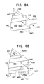
- anchor flange 420 is bent downward, and riser-engaging tab 432 is dimensioned and configured to be bent around leg portion 430 to engage riser portion 522 of the immediately preceding plate that supports plate 410 by being inserted into the conduit defined by baffle portion 412, the baffle portion 512 of the preceding plate and riser portions 522 (only one of which is shown).
- Sub-riser-engaging tab 450 is shown beneath the immediately preceding plate 510, the anchor flange of which is omitted from Figure 8A for clarity, but is shown in Figure 8B.
- Riser-engaging tab 532 shown in Figure 8B in dotted outline, is bent over and around leg portion 530, and is inserted into the conduit defined in part by riser portion 622 of the second preceding plate to plate 410, to engage both riser 622 and sub-riser-engaging tab 450.
- the anchor flange of plate 610 is not shown.
- the sub-riser-engaging tab 550 of first preceding plate 510 is seen extending beneath plate 610, in position to engage the riser portion together with the sub-riser-engaging tab of plate 610.
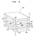
- FIG. 9 A monolith comprising plates as shown in Figure 7, linked together as shown in Figure 8B, is illustrated in Figure 9, wherein plate 410 is centrally disposed.
- the exterior portion of riser-engaging tab 432 is seen folded over leg portion 430 and is seen in dotted outline engaging riser portion 522 of the immediately preceding plate.
- the sub-riser-engaging tab attached to leg portion 430 engages riser portion 622, but is not visible.
- riser-engaging tab 432 is shown, entirely in dotted outline, folded over leg portion 430 to engage riser portion 522.
- sub-riser-engaging tab 450 is visible extending beneath baffle portion 512 and engaging riser portion 622 of the plate supporting plate 510.
Landscapes
- Chemical & Material Sciences (AREA)
- Engineering & Computer Science (AREA)
- Chemical Kinetics & Catalysis (AREA)
- Mechanical Engineering (AREA)
- General Engineering & Computer Science (AREA)
- Toxicology (AREA)
- Combustion & Propulsion (AREA)
- Health & Medical Sciences (AREA)
- Organic Chemistry (AREA)
- Physics & Mathematics (AREA)
- Thermal Sciences (AREA)
- Physical Or Chemical Processes And Apparatus (AREA)
- Laminated Bodies (AREA)
- Heat-Exchange Devices With Radiators And Conduit Assemblies (AREA)
- Catalysts (AREA)
Abstract
Description
R = L + 2Y. In addition, the
Claims (15)
- A plate (10 10', 410) used in the assembly of a monolith, the plate comprising;a central baffle portion (12) having two sides (14a, 14b) and two ends (16);a support flange (18) attached to each end (16) of the plate (10) for supporting a succeeding plate in parallel, spaced relation to the plate (10) the support flange having a riser portion (22); andanchor flanges (20), having a length equal to at least twice the height (H) of the riser portion (22) of the support flange (18), attached to each end (16) of the plate (10 10', 410) for closing off the comer of a monolith comprising the plate (10, 10', 410).
- The plate (10, 10', 410) of claim 1 wherein each support flange (18) comprises a riser portion (22) having two sides and being attached on one side to an end (16) of the baffle portion (12), and a landing portion (24a) attached to the other side of the riser portion (22); and
wherein each anchor flange (20) extends from the baffle portion (12) therefrom for a length equal to at least twice the width of the riser portion (22). - The plate (10, 10', 410) of claim 2 wherein the anchor flange (20) further comprises a leg portion (30) and a riser-engaging tab (32) extending from the leg portion in a direction perpendicular to the side (14a, 14b) of the plate (10, 10', 410) for engaging the riser portion (22) of a preceding plate support flange (18) on which the plate (10, 10', 410) may be mounted.
- The plate (10, 10', 410) of claim 3 further comprising a subriser-engaging tab (450) attached to the leg portion (30) and extending therefrom for engaging the riser portion (22) of the support flange (18) of a second preceding plate on which the preceding plate is mounted.
- The plate (10, 10', 410) of claim 1 comprising a catalytic material coated thereon.
- The plate (10, 10', 410) of claim 1 in its flat configuration, wherein the central baffle portion (12) is generally rectangular and has a width (W) defined by a pair of generally straight, parallel side edges (14a, 14b) and is mounted on the ends (16) by a flange border (14);the support flanges (18) are attached at either end of the baffle portion (12), each support flange (18) comprising a riser portion (22) and a landing portion (24a), the riser portion (22) having two sides and two ends and being attached on one side to the baffle portion (12) at the flange border (16), and being bendable to a substantially perpendicular relationship with the baffle portion (12), the landing portion (24a) being attached to the other side of the riser portion (22) and being bendable to be substantially parallel to the baffle portion (12), for supporting a succeeding plate configured like the first plate (10), the end-to-end length of the riser portion (22) being less than the width (W) of the baffle portion (12), and the riser portion (22) being disposed centrally between the side edges (14a, 14b) of the baffle portion; anda pair of anchor flanges (20) are attached to each end (16) of the baffle portion (12) beside each end of the riser portions (22), each anchor flange (20) being contiguous with the support flange (18) and being bendable to a substantially perpendicular relationship with the baffle portion (12) in a direction opposite to that of the riser portion (22) and having a width equal to about one-half the difference between the end-to-end length of the riser portion (22) and the width of the baffle portion (12) for at least partially closing off the comers of a monolith comprising the plate (10, 10', 410).
- The plate (10, 10', 410) of claim 6 wherein each anchor flange (20) comprises(i) a leg portion (30) for at least partially closing off the comer of a monolith comprising the plate, (10, 10', 410) and(ii) a riser-engaging tab (32) attached to and extending from the leg portion (30) away from the riser portion (22), the riser-engaging tab (32) having a width not greater than the width of the riser portion (22), the riser-engaging tab (32) having a length greater than the width of the leg portion (30), for engaging the riser portion (22) of a preceding plate configured like the first plate (10, 10', 410), on which the first plate (10, 10', 410) is mounted.
- The plate of claim 7 wherein the width W of the baffle portion (12) exceeds the length R of each riser portion (22) by an amount designated 2T, and wherein the width of each leg portion (30) equals T, and wherein the width W of the baffle portion (12) exceeds the length D of the baffle portion (12) by an amount designated 2S, and wherein the width of each riser portion (22) equals S.
- The plate of claim 7 wherein the leg portion (30) has a length greater than twice the width of the riser portion (22).
- The plate (10, 10', 410) of claim 7, claim 8 or claim 9 wherein each anchor flange (20) further comprises a sub-riser-engaging tab (450) connected to and extending from the leg portion (430) towards the landing portion (424a) from a point separated from the baffle portion (412) by at least the width of the riser portion (422), the sub-riser-engaging tab (450) having a width not greater than the width of the riser portion (422), for engaging the riser portion (422) of a second preceding plate configured like the first plate (10, 10', 410) on which a first preceding plate is mounted.
- The plate (10, 10', 410) of claim 7 further comprising a catalytic material coated thereon.
- A monolith (38) comprising at least a first plate (10, 10', 410), a succeeding plate and a preceding plate, at least the first plate (10, 10', 410) and the succeeding plate being described in any one of claim 1, claim 6 or claim 8, and the preceding plate comprising at least a support flange (18) wherein on the first plate (10, 10', 410), the riser portions (22) of the support flanges (18) are bent at right angles to the baffle portion and the landing portions (24a) of the support flanges (18) are bent at right angles to the riser portions (22), to support the succeeding plate in spaced, parallel, mounted relation to the first plate (10, 10', 410);the anchor flanges (20) of the succeeding plate being bent at right angles to the baffle portion (12) thereof towards the first plate (10, 10', 410); andthe first plate (10, 10', 410) being mounted on landing portions (24a) of the supporting flanges (518) of the preceding plate and having its anchor flanges (520) at right angles to its baffle portion (512);whereby the baffle portion (12) and riser portions (22) of the first plate (10, 10', 410) together with the baffle portion (12) of the succeeding plate define a first open-ended gas flow conduit (34) through the monolith (38); andwhereby the baffle portion (512) and riser portions (522) of the preceding plate together with the baffle portion (12) of the first plate (10, 10', 410) define a second, open-ended gas flow conduit (40) through the monolith (38), the second gas flow conduit (40) being disposed at right angles to the first gas flow conduit (34); andwhereby the corners of the monolith (38) defined by the first plate (10, 10', 410), the succeeding plate and the preceding plate are closed off by the anchor flanges (20) of the first plate (10, 10', 410) and the succeeding plate.
- The monolith (38) of claim 12 wherein each anchor flange (20) comprises a leg portion (30) and a riser-engaging tab (32) attached to the leg portion (30) and extending away from the support flange (18), for engaging the riser portion (22) of a preceding plate, the riser-engaging tab (32) having a width not greater than the width of the riser portion (22) of the support flange (18).
- The monolith (38) of claim 13 further comprising high surface area catalytic material-bearing inserts in the conduits (34, 40).
- The monolith (38) of claim 13 further comprising a catalytic material coated thereon.
Applications Claiming Priority (3)
| Application Number | Priority Date | Filing Date | Title |
|---|---|---|---|
| US08/381,804 US5681538A (en) | 1995-02-01 | 1995-02-01 | Metallic monolith and plates for the assembly thereof |
| US381804 | 1995-02-01 | ||
| PCT/US1996/001046 WO1996024020A1 (en) | 1995-02-01 | 1996-01-30 | Metallic monolith and plates for the assembly thereof |
Publications (2)
| Publication Number | Publication Date |
|---|---|
| EP0807236A1 EP0807236A1 (en) | 1997-11-19 |
| EP0807236B1 true EP0807236B1 (en) | 2001-08-22 |
Family
ID=23506435
Family Applications (1)
| Application Number | Title | Priority Date | Filing Date |
|---|---|---|---|
| EP96903686A Expired - Lifetime EP0807236B1 (en) | 1995-02-01 | 1996-01-30 | Metallic monolith and plates for the assembly thereof |
Country Status (6)
| Country | Link |
|---|---|
| US (1) | US5681538A (en) |
| EP (1) | EP0807236B1 (en) |
| JP (1) | JPH10513254A (en) |
| AT (1) | ATE204639T1 (en) |
| DE (1) | DE69614665T2 (en) |
| WO (1) | WO1996024020A1 (en) |
Families Citing this family (18)
| Publication number | Priority date | Publication date | Assignee | Title |
|---|---|---|---|---|
| SE521382C2 (en) * | 1998-09-01 | 2003-10-28 | Compact Plate Ab | Cross current type heat exchanger |
| AP1457A (en) * | 2000-01-11 | 2005-09-30 | Accentus Plc | Catalytic reactor for performing reactions between gases at elevated temperatures. |
| EP1236505A1 (en) * | 2001-02-27 | 2002-09-04 | Methanol Casale S.A. | Method for carrying out chemical reactions in pseudo-isothermal conditions |
| GB0116894D0 (en) * | 2001-07-11 | 2001-09-05 | Accentus Plc | Catalytic reactor |
| US20060260790A1 (en) * | 2005-05-18 | 2006-11-23 | Mark Theno | Heat exchanger core |
| US8047272B2 (en) * | 2005-09-13 | 2011-11-01 | Catacel Corp. | High-temperature heat exchanger |
| US7594326B2 (en) * | 2005-09-13 | 2009-09-29 | Catacel Corp. | Method for making a low-cost high-temperature heat exchanger |
| US7591301B2 (en) * | 2005-09-13 | 2009-09-22 | Catacel Corp. | Low-cost high-temperature heat exchanger |
| CN100561098C (en) * | 2006-04-29 | 2009-11-18 | 绍兴吉利尔科技发展有限公司 | A gas heat exchanger |
| US8646516B2 (en) * | 2006-08-17 | 2014-02-11 | Pana Canada Corporation | Alternating plate headerless heat exchangers |
| WO2010110833A2 (en) * | 2008-12-31 | 2010-09-30 | Frontline Aerospace, Inc. | Recuperator for gas turbine engines |
| WO2011148216A1 (en) * | 2010-05-26 | 2011-12-01 | Mircea Dinulescu | Plate-type heat exchanger |
| FR3003637B1 (en) * | 2013-03-21 | 2015-04-17 | Nexson Group | PLATE FOR THERMAL EXCHANGER AND THERMAL EXCHANGER INCORPORATING SUCH PLATE |
| US12352459B2 (en) * | 2015-11-23 | 2025-07-08 | Ffi Ionix Ip, Inc. | Advanced energy recovery ventilator |
| KR20190003137A (en) * | 2017-06-30 | 2019-01-09 | 현대자동차주식회사 | Fuel reforming system |
| PL3457067T3 (en) * | 2017-09-15 | 2023-06-19 | Alfa Laval Corporate Ab | Baffle support and baffle |
| US11022384B2 (en) * | 2018-02-19 | 2021-06-01 | Honeywell International Inc. | Framed heat exchanger core design-fabrication |
| FR3108714B1 (en) * | 2020-03-26 | 2022-12-23 | Axens | Plate heat exchanger |
Family Cites Families (11)
| Publication number | Priority date | Publication date | Assignee | Title |
|---|---|---|---|---|
| DE360058C (en) * | 1919-11-15 | 1922-09-29 | Camille Turquois | Device for automatic adjustment of the altitude correction apparatus for aircraft engines |
| US3067002A (en) * | 1960-03-23 | 1962-12-04 | Socony Mobil Oil Co Inc | Method of treating exhaust gases of internal combustion engines |
| DE2817990C2 (en) * | 1978-04-25 | 1982-04-01 | Süddeutsche Kühlerfabrik Julius Fr. Behr GmbH & Co KG, 7000 Stuttgart | Cross-flow heat exchanger unit in lightweight construction |
| DE3131091A1 (en) * | 1981-08-06 | 1983-02-24 | Klöckner-Humboldt-Deutz AG, 5000 Köln | RING-SHAPED RECUPERATIVE HEAT EXCHANGER |
| FR2562997B1 (en) * | 1984-04-19 | 1988-09-23 | Vicarb Sa | PLATE HEAT EXCHANGERS AND NEW TYPE OF PLATES FOR PROVIDING SUCH EXCHANGERS |
| US4848450A (en) * | 1988-02-09 | 1989-07-18 | C & J Jones (1985) Limited | Heat exchanger |
| FR2649192A1 (en) * | 1989-06-30 | 1991-01-04 | Inst Francais Du Petrole | METHOD AND DEVICE FOR SIMULTANEOUS TRANSFER OF MATERIAL AND HEAT |
| JPH0724575Y2 (en) * | 1989-12-12 | 1995-06-05 | ニチアス株式会社 | Exhaust gas purification device for internal combustion engine |
| US5072790A (en) * | 1990-07-30 | 1991-12-17 | Jones Environics Ltd. | Heat exchanger core construction |
| US5303547A (en) * | 1992-04-15 | 1994-04-19 | Amoco Corporation | Emissions control system and method |
| EP0592713A1 (en) * | 1992-10-15 | 1994-04-20 | Corning Incorporated | Engine exhaust system with reduced hydrocarbon emissions |
-
1995
- 1995-02-01 US US08/381,804 patent/US5681538A/en not_active Expired - Fee Related
-
1996
- 1996-01-30 JP JP8523633A patent/JPH10513254A/en not_active Ceased
- 1996-01-30 EP EP96903686A patent/EP0807236B1/en not_active Expired - Lifetime
- 1996-01-30 DE DE69614665T patent/DE69614665T2/en not_active Expired - Fee Related
- 1996-01-30 WO PCT/US1996/001046 patent/WO1996024020A1/en not_active Ceased
- 1996-01-30 AT AT96903686T patent/ATE204639T1/en not_active IP Right Cessation
Also Published As
| Publication number | Publication date |
|---|---|
| DE69614665T2 (en) | 2002-03-07 |
| ATE204639T1 (en) | 2001-09-15 |
| DE69614665D1 (en) | 2001-09-27 |
| JPH10513254A (en) | 1998-12-15 |
| EP0807236A1 (en) | 1997-11-19 |
| US5681538A (en) | 1997-10-28 |
| WO1996024020A1 (en) | 1996-08-08 |
Similar Documents
| Publication | Publication Date | Title |
|---|---|---|
| EP0807236B1 (en) | Metallic monolith and plates for the assembly thereof | |
| US4131159A (en) | Heat exchanger | |
| JPH0328913Y2 (en) | ||
| US5162288A (en) | Catalyst element for heterogeneous reactions | |
| US6318456B1 (en) | Heat exchanger of the crosscurrent type | |
| US20010038811A1 (en) | Structured packing and element therefor | |
| US4179781A (en) | Method for forming a heat exchanger core | |
| JPS6183881A (en) | Two fluid heat exchanger | |
| US5384100A (en) | Baffle assembly for catalytic converter | |
| EP0916400A1 (en) | Distillation column employing structured packing which reduces wall flow | |
| JPWO1999008789A1 (en) | Metallic thin plate for metallic catalyst carrier and metallic catalytic converter using the same | |
| US20030098146A1 (en) | Heat exchanger | |
| US20010051119A1 (en) | Structured packing and element therefor | |
| JPH0655258B2 (en) | Catalyst support for catalytic reactor for exhaust gas purification | |
| CN103228352A (en) | Catalytic reactor and catalyst structure | |
| JP2987999B2 (en) | Catalyst carrier for internal combustion engine | |
| JPH06254410A (en) | Catalyst carrier for exhaust emission control device | |
| JPH04271846A (en) | Catalyst carrier for exhaust gas purification device and manufacturing method thereof | |
| KR100313037B1 (en) | Catalytic Converter | |
| JPH08312339A (en) | Exhaust emission control device | |
| JPH0356253Y2 (en) | ||
| JPH08312338A (en) | Exhaust emission control device | |
| JP2008080214A (en) | Metal catalyst carrier | |
| CN117739719A (en) | Efficient plate heat exchanger | |
| JPS61116291A (en) | Horizontal lamination type heat exchanger |
Legal Events
| Date | Code | Title | Description |
|---|---|---|---|
| PUAI | Public reference made under article 153(3) epc to a published international application that has entered the european phase |
Free format text: ORIGINAL CODE: 0009012 |
|
| 17P | Request for examination filed |
Effective date: 19970711 |
|
| AK | Designated contracting states |
Kind code of ref document: A1 Designated state(s): AT BE CH DE DK ES FR GB GR IE IT LI LU MC NL PT SE |
|
| 17Q | First examination report despatched |
Effective date: 19990223 |
|
| GRAG | Despatch of communication of intention to grant |
Free format text: ORIGINAL CODE: EPIDOS AGRA |
|
| GRAG | Despatch of communication of intention to grant |
Free format text: ORIGINAL CODE: EPIDOS AGRA |
|
| GRAH | Despatch of communication of intention to grant a patent |
Free format text: ORIGINAL CODE: EPIDOS IGRA |
|
| GRAH | Despatch of communication of intention to grant a patent |
Free format text: ORIGINAL CODE: EPIDOS IGRA |
|
| GRAA | (expected) grant |
Free format text: ORIGINAL CODE: 0009210 |
|
| AK | Designated contracting states |
Kind code of ref document: B1 Designated state(s): AT BE CH DE DK ES FR GB GR IE IT LI LU MC NL PT SE |
|
| PG25 | Lapsed in a contracting state [announced via postgrant information from national office to epo] |
Ref country code: NL Free format text: LAPSE BECAUSE OF FAILURE TO SUBMIT A TRANSLATION OF THE DESCRIPTION OR TO PAY THE FEE WITHIN THE PRESCRIBED TIME-LIMIT Effective date: 20010822 Ref country code: LI Free format text: LAPSE BECAUSE OF FAILURE TO SUBMIT A TRANSLATION OF THE DESCRIPTION OR TO PAY THE FEE WITHIN THE PRESCRIBED TIME-LIMIT Effective date: 20010822 Ref country code: IT Free format text: LAPSE BECAUSE OF FAILURE TO SUBMIT A TRANSLATION OF THE DESCRIPTION OR TO PAY THE FEE WITHIN THE PRESCRIBED TIME-LIMIT;WARNING: LAPSES OF ITALIAN PATENTS WITH EFFECTIVE DATE BEFORE 2007 MAY HAVE OCCURRED AT ANY TIME BEFORE 2007. THE CORRECT EFFECTIVE DATE MAY BE DIFFERENT FROM THE ONE RECORDED. Effective date: 20010822 Ref country code: FR Free format text: LAPSE BECAUSE OF FAILURE TO SUBMIT A TRANSLATION OF THE DESCRIPTION OR TO PAY THE FEE WITHIN THE PRESCRIBED TIME-LIMIT Effective date: 20010822 Ref country code: CH Free format text: LAPSE BECAUSE OF FAILURE TO SUBMIT A TRANSLATION OF THE DESCRIPTION OR TO PAY THE FEE WITHIN THE PRESCRIBED TIME-LIMIT Effective date: 20010822 Ref country code: BE Free format text: LAPSE BECAUSE OF FAILURE TO SUBMIT A TRANSLATION OF THE DESCRIPTION OR TO PAY THE FEE WITHIN THE PRESCRIBED TIME-LIMIT Effective date: 20010822 Ref country code: AT Free format text: LAPSE BECAUSE OF FAILURE TO SUBMIT A TRANSLATION OF THE DESCRIPTION OR TO PAY THE FEE WITHIN THE PRESCRIBED TIME-LIMIT Effective date: 20010822 |
|
| REF | Corresponds to: |
Ref document number: 204639 Country of ref document: AT Date of ref document: 20010915 Kind code of ref document: T |
|
| REG | Reference to a national code |
Ref country code: CH Ref legal event code: EP |
|
| REF | Corresponds to: |
Ref document number: 69614665 Country of ref document: DE Date of ref document: 20010927 |
|
| REG | Reference to a national code |
Ref country code: IE Ref legal event code: FG4D |
|
| PG25 | Lapsed in a contracting state [announced via postgrant information from national office to epo] |
Ref country code: SE Free format text: LAPSE BECAUSE OF FAILURE TO SUBMIT A TRANSLATION OF THE DESCRIPTION OR TO PAY THE FEE WITHIN THE PRESCRIBED TIME-LIMIT Effective date: 20011122 Ref country code: PT Free format text: LAPSE BECAUSE OF FAILURE TO SUBMIT A TRANSLATION OF THE DESCRIPTION OR TO PAY THE FEE WITHIN THE PRESCRIBED TIME-LIMIT Effective date: 20011122 Ref country code: DK Free format text: LAPSE BECAUSE OF FAILURE TO SUBMIT A TRANSLATION OF THE DESCRIPTION OR TO PAY THE FEE WITHIN THE PRESCRIBED TIME-LIMIT Effective date: 20011122 |
|
| PG25 | Lapsed in a contracting state [announced via postgrant information from national office to epo] |
Ref country code: GR Free format text: LAPSE BECAUSE OF FAILURE TO SUBMIT A TRANSLATION OF THE DESCRIPTION OR TO PAY THE FEE WITHIN THE PRESCRIBED TIME-LIMIT Effective date: 20011123 |
|
| REG | Reference to a national code |
Ref country code: GB Ref legal event code: IF02 |
|
| PGFP | Annual fee paid to national office [announced via postgrant information from national office to epo] |
Ref country code: DE Payment date: 20020103 Year of fee payment: 7 |
|
| EN | Fr: translation not filed | ||
| PG25 | Lapsed in a contracting state [announced via postgrant information from national office to epo] |
Ref country code: LU Free format text: LAPSE BECAUSE OF NON-PAYMENT OF DUE FEES Effective date: 20020130 Ref country code: IE Free format text: LAPSE BECAUSE OF NON-PAYMENT OF DUE FEES Effective date: 20020130 |
|
| NLV1 | Nl: lapsed or annulled due to failure to fulfill the requirements of art. 29p and 29m of the patents act | ||
| PGFP | Annual fee paid to national office [announced via postgrant information from national office to epo] |
Ref country code: GB Payment date: 20020227 Year of fee payment: 7 |
|
| PG25 | Lapsed in a contracting state [announced via postgrant information from national office to epo] |
Ref country code: ES Free format text: LAPSE BECAUSE OF FAILURE TO SUBMIT A TRANSLATION OF THE DESCRIPTION OR TO PAY THE FEE WITHIN THE PRESCRIBED TIME-LIMIT Effective date: 20020228 |
|
| REG | Reference to a national code |
Ref country code: CH Ref legal event code: PL |
|
| PLBE | No opposition filed within time limit |
Free format text: ORIGINAL CODE: 0009261 |
|
| STAA | Information on the status of an ep patent application or granted ep patent |
Free format text: STATUS: NO OPPOSITION FILED WITHIN TIME LIMIT |
|
| PG25 | Lapsed in a contracting state [announced via postgrant information from national office to epo] |
Ref country code: MC Free format text: LAPSE BECAUSE OF NON-PAYMENT OF DUE FEES Effective date: 20020801 |
|
| 26N | No opposition filed | ||
| REG | Reference to a national code |
Ref country code: IE Ref legal event code: MM4A |
|
| PG25 | Lapsed in a contracting state [announced via postgrant information from national office to epo] |
Ref country code: GB Free format text: LAPSE BECAUSE OF NON-PAYMENT OF DUE FEES Effective date: 20030130 |
|
| PG25 | Lapsed in a contracting state [announced via postgrant information from national office to epo] |
Ref country code: DE Free format text: LAPSE BECAUSE OF NON-PAYMENT OF DUE FEES Effective date: 20030801 |
|
| GBPC | Gb: european patent ceased through non-payment of renewal fee |