EP0807195B1 - Leitplanke mit einer stossdämpfenden vorrichtung - Google Patents
Leitplanke mit einer stossdämpfenden vorrichtung Download PDFInfo
- Publication number
- EP0807195B1 EP0807195B1 EP96902326A EP96902326A EP0807195B1 EP 0807195 B1 EP0807195 B1 EP 0807195B1 EP 96902326 A EP96902326 A EP 96902326A EP 96902326 A EP96902326 A EP 96902326A EP 0807195 B1 EP0807195 B1 EP 0807195B1
- Authority
- EP
- European Patent Office
- Prior art keywords
- arms
- rail
- barrier
- crash barrier
- shock
- Prior art date
- Legal status (The legal status is an assumption and is not a legal conclusion. Google has not performed a legal analysis and makes no representation as to the accuracy of the status listed.)
- Expired - Lifetime
Links
- 230000004888 barrier function Effects 0.000 title claims abstract description 19
- 230000035939 shock Effects 0.000 claims description 18
- 238000010521 absorption reaction Methods 0.000 claims description 15
- 239000006096 absorbing agent Substances 0.000 claims description 12
- 230000005489 elastic deformation Effects 0.000 claims description 3
- 230000000694 effects Effects 0.000 description 9
- 230000000750 progressive effect Effects 0.000 description 4
- 230000004048 modification Effects 0.000 description 3
- 238000012986 modification Methods 0.000 description 3
- 238000005452 bending Methods 0.000 description 2
- 230000007423 decrease Effects 0.000 description 2
- 238000006073 displacement reaction Methods 0.000 description 2
- 230000000712 assembly Effects 0.000 description 1
- 238000000429 assembly Methods 0.000 description 1
- 238000006243 chemical reaction Methods 0.000 description 1
- 230000000295 complement effect Effects 0.000 description 1
- 238000013016 damping Methods 0.000 description 1
- 230000003247 decreasing effect Effects 0.000 description 1
- 238000005259 measurement Methods 0.000 description 1
- 230000001681 protective effect Effects 0.000 description 1
Images
Classifications
-
- E—FIXED CONSTRUCTIONS
- E01—CONSTRUCTION OF ROADS, RAILWAYS, OR BRIDGES
- E01F—ADDITIONAL WORK, SUCH AS EQUIPPING ROADS OR THE CONSTRUCTION OF PLATFORMS, HELICOPTER LANDING STAGES, SIGNS, SNOW FENCES, OR THE LIKE
- E01F15/00—Safety arrangements for slowing, redirecting or stopping errant vehicles, e.g. guard posts or bollards; Arrangements for reducing damage to roadside structures due to vehicular impact
- E01F15/02—Continuous barriers extending along roads or between traffic lanes
- E01F15/04—Continuous barriers extending along roads or between traffic lanes essentially made of longitudinal beams or rigid strips supported above ground at spaced points
- E01F15/0407—Metal rails
- E01F15/0438—Spacers between rails and posts, e.g. energy-absorbing means
Definitions
- the present invention relates to the field of slide rails security, which generally consists of a profiled rail mounted on supports vertical stuck in the ground, are arranged on either side of a road.
- These can be slides protecting a conventional road, a motorway, or more specifically, a racing circuit.
- the rail of such a slide has a section in W lying, and its vertical supports are U or C section profiles.
- a device shock absorber comprising between a slide rail and supports vertical V-shaped deformable elements having both other of a central support area on a vertical support of the V-shaped arms each ending with a fixing zone with freedom of sliding on the slide rail.
- shock absorbers thus known still do not avoid the disadvantages mentioned above of the geometry modifications resulting from the inevitable plastic deformations in the event of large shocks, all the less that attachment zones of neighboring elements can then come into rigid abutment between them.
- the present invention relates to a shock absorber device, interposed between each vertical support and the rail, adapted to deform with absorption of energy allowing a sufficiently soft damping of said shock, while not giving rise to a tilting or sinking of the rail.
- the slide when a vehicle hits the rail at an angle of incidence not too important, the slide will keep, to a certain extent, its deflector function. Indeed, and as will be better understood by the next, the rail, which, not being strictly subject to its supports vertical, can deform steadily, first bends so as to extend parallel to the direction of incidence of the vehicle, then gradually returns to a position parallel to its initial position. This, allowing sliding against the vehicle rail, allows this last in line with the road.
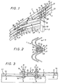
- Figures 1 to 5 show a first example of a slide road safety according to the present invention.
- This slide comprises, in known manner, a rail 1, in practice consisting of two coated W profiles arranged one above the other.
- This rail is carried by vertical supports 2 stuck in the ground, here posts of rectangular section, as seen in Figure 1.
- shock energy absorber comprising two arms 3A and 3B which, starting from the post 2, are arranged substantially in a V, in a horizontal plane, their free ends carrying the rail.
- the arms 3A and 3B are profiles of the same section as the slide rail, here a pair of coated W profiles arranged one above the other.
- these arms may have different sections of those of rail 1, provided that they have good resistance to vertical stresses, so that they can only deform in the horizontal plane in which they extend.
- Such a device 3 must be able to absorb most of the energy of the impact of a motor vehicle on the rail, so that the latter is not, at least, not bent by bending between two posts or tilted by deformation of the posts 2.
- this energy absorption is done by opening arms 3A and 3B, so that the slide only deforms by approximation of rail 1 towards posts 2.
- the arms 3A and 3B are formed by the two ends of the same profile curved, at least part of the absorption of shock energy being by plastic deformation at the elbow of said profile.
- the initial opening angle of the arms 3A and 3B is of the order of 45 °.
- the withdrawal of the rail 1 towards the post 2, in this case, is substantially proportional, at least initially, to the variation of the angle arms opening.
- the resistance to deformation of the slide remains constant during movement, and, therefore, energy absorption takes place regularly or gradually during arm opening movement.
- longitudinal slots 9 and 8 are provided on the flat central parts, 20 and 21 respectively, of the rail 1 and of the arms 3A and 3B.
- Two slots 9 are arranged, one above the other, on the free ends of the arms 3A and 3B, each of these slots being aligned with a slot 8 of the rail 1.
- Two attachment devices 11 are associated with each pair of aligned slots 8 and 9.
- Each of these devices includes, as seen in FIGS. 2 and 3, a threaded rod 5 at the two ends of which are installed bolts 6, said threaded rod passing through the slot of one of the parts of the sliding assembly as well as a bore of the other part formed in the alignment of its own slot.
- one of the attachment devices 11 is integral with the rail 1 and slides in a slot 9 of the curved profile 3, while the other device 11 is integral with the end of the arm of the section 3 in which is formed said slot 9, and slides in the corresponding slot 8 of the rail 1.
- the devices attachment 11 are each in abutment against one end of the slot corresponding, the slot 9 extending from the device 11 which passes through it, towards the post 2, while the slot 8 moves away, from the device 11 which la cross, of this post 2.
- each of the arms 3A and 3B cannot therefore slide on rail 1 than moving away from post 2.
- the freedom of sliding of the arms relative to the rail is limited to the freedom that arms 3A and 3B have to move away from each other.
- the arms 3A and 3B actually carry the rail 1 while being able to move away from each other freely, without exerting any constraint on the latter.
- the absorption of the impact energy is made, at least in part, thanks to the interposition of means friction or braking between the sliding mounted parts one by relation to the other, that is to say, in the embodiment shown in Figures 1 to 5, the free ends of the arms 3A and 3B and the rail 1.
- this means of absorbing the impact energy is associated with the one described above.
- This association is to be preferred because it presents good efficiency / cost ratio, it facilitates adjustment of the coefficient braking of the slide, and, finally, it makes it possible to avoid any unwanted elastic deformation.
- Figures 2 and 3 show an example of arrangement using such a means of friction between two parts sliding relative to each other.
- Friction plates 12 and 14 are fixed on, respectively, one and the other of parts 1 and 3 of the sliding assembly, at the respective flat central parts 21 and 20 of the latter, so as to be in contact with one another, between said parts 1 and 3 of the sliding assembly, as can be seen in FIG. 2.
- a pair of plates 12 and 14 is associated with each pair of aligned slots 8 and 9.
- the plates 12 and 14 of such a pair are aligned with the slots 8 and 9 corresponding, an end portion of the plate 12 being located view of an end portion of the plate 14.
- slots 13 and 15 are formed in the plates, respectively, 12 and 14, in the extension slots, respectively, 8 and 9.
- the bolts 6 of the hooking devices 11, to which are associated with axial action elastic washers 16, are tightened with a determined couple.
- the fastening devices 11 then play a role of means adapted to clamp against each other, with an adjustable force, both parts of the sliding assembly.
- the means of friction 12 and 14 interposed between the two parts of the assembly sliding progressively brake the relative movement of these parts sliding.
- the plates 12 and 14 have a wedge shape, the thickness of each of them increasing with the as we move away from the end opposite the other room.
- the slope of the active surfaces of the plates 12 and 14 is, well heard, chosen so as to compensate for the degressive braking effect, to that energy absorption takes place regularly, or even in a way progressive, during the opening movement of the arms.
- the shapes of these plates 12 and 14 are chosen to be complementary, so that that they extend against each other throughout the movement.
- FIG. 1 to 3 corresponds to the specific case rails formed by the association of two coated W profiles arranged one above each other.
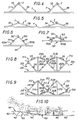
- the arms 103A and 103B are telescopic. Each of these arms therefore comprises two parts 111 sliding relative to one another.
- the opening of the arms 103A and 103B is therefore possible, without modification of the interval separating the attachment points with the rail 101, by reducing the length of these arms, as can be seen in the figures 6 and 7.
- the ends of the arms 103A and 103B will be mounted on vertical axes integral with rail 101, so that these arms can freely rotate in the horizontal plane in which they extend.
- friction means such as those described previously will be interposed between the two sliding parts of each arms, in order to absorb, at least in part, the energy of the shock.
- Figures 8 and 9 show a second alternative embodiment of the present invention.
- This variant corresponds, in fact, to the variant of FIGS. 6 and 7, an additional absorbing device 213, comprising two arms 213A and 213B, being associated with the absorber device 203, each of said additional arms comprising two parts 211 sliding relative to each other.
- Additional arms 213A and 213B starting from the vertical support 202, are arranged substantially in a V, open in the other direction than that formed by arms 203A and 203B, the free ends of these arms additional being connected to the rail by crosspieces 210, perpendicular to the latter.
- Friction means such as those described above, are interposed between the two sliding parts of each of the arms 213A and 213B, as well as each of the arms 203A and 203B.
- the initial openings of the respective arms of these devices absorbers 203 and 213 will therefore be chosen so that braking decreasing on the one is compensated by the progressive braking on the other.
- This alternative embodiment therefore avoids having to implement progressive braking means, such as those described in the first example of implementation.
- each arm 213A, 213B being stressed only in traction during energy absorption impact, we can therefore replace each arm 213A, 213B with a cable associated with braking means equivalent to friction means 12, 14 of Figures 2 and 3.
- Figure 10 shows, schematically, the deformation of a slide according to the second variant described, when a motor vehicle hits rail 101 with a not too large angle of incidence.
- Rail 101 not being strictly subject to its supports vertical 102, can deform regularly, without effect sinking due to the reaction of the posts. It therefore bends, at the place of the impact, so as to extend parallel to the direction of incidence of the vehicle, then, as one moves away from the point of impact, returns gradually in a position parallel to its initial position. Of course, this deformation of the rail is done by always approaching the posts 102, which allows the absorption of shock energy.
- the regular deformation of the rail 101 allows the vehicle to slide against it, making it possible to bring this last in line with the road.
- V-shaped arrangement of the arms of the shock energy absorption devices to best combat the risk of longitudinal drive of the rail relative to its supports, when vehicle, in particular a Formula 1 sports car, runs against said rail.
- Another advantage provided by the present invention comes from the fact that only shock energy absorption devices and, to a lesser extent measurement, the rail, undergo deformations following an impact. The posts of support, they are spared. This replaces much more easily the slides having suffered a significant shock.
Landscapes
- Engineering & Computer Science (AREA)
- Architecture (AREA)
- Civil Engineering (AREA)
- Structural Engineering (AREA)
- Vibration Dampers (AREA)
- Refuge Islands, Traffic Blockers, Or Guard Fence (AREA)
- Road Signs Or Road Markings (AREA)
- Platform Screen Doors And Railroad Systems (AREA)
Claims (7)
- Leitplanke, die zwischen einer Leitschiene (1) und vertikalen Trägern (2) stoßdämpfende Vorrichtungen (3) aufweist, die aus verformbaren V-förmigen Elementen bestehen, die zu beiden Seiten eines zentralen Bereichs der Anlage an den vertikalen Trägern (2) Arme aufweisen, an deren Enden auf der Leitschiene (1) gleitende Anlagebereiche vorgesehen sind, dadurch gekennzeichnet, daß die von den verformbaren Elementen gebildeten Arme (3A, 3B) Abschnitte (3A, 3B) eines gekrümmten Profils zu beiden Seiten eines Biegungsbereichs sind, die in ihren Bereichen der Anlage an der Leitschiene (1) mit Reibmitteln (12, 14) ausgerüstet sind, die zwischen diese Arme und die Leitschiene eingesetzt sind und dazu ausgelegt sind, die Absorption der Aufprallenergie mindestens konstant zu halten, die innerhalb einer Grenze der elastischen Verformung durch Reibung vor sich geht und bei Überschreiten dieser Grenze durch plastische Verformung dieses Biegungsbereichs weiter stattfindet.
- Leitplanke nach Anspruch 1, dadurch gekennzeichnet, daß die Reibmittel (12, 14) zwischen die Auflageendbereiche und die Leitschiene (1) eingesetzt sind und keilförmige Teile aufweisen, die dazu ausgelegt sind, die Aufprallenergie allmählich zu absorbieren.
- Leitplanke nach Anspruch 2, dadurch gekennzeichnet, daß den Anlageendbereichen und der Leitschiene (1) Mittel (11) zugeordnet sind, die diese mit einer einstellbaren Kraft gegeneinanderpressen können.
- Leitplanke nach einem der Ansprüche 1 bis 3, dadurch gekennzeichnet, daß die Arme (3A, 3B) der dämpfenden Vorrichtung (3) aus einem gekrümmten Profil mit demselben Querschnitt wie die Leitschiene bestehen.
- Leitplanke nach Anspruch 1, gekennzeichnet durch verformbare Elemente (103) mit Teleskoparmen (103A, 103B), wobei die Reibmittel zwischen die gleitenden Teile jedes Arms eingesetzt sind.
- Leitplanke nach Anspruch 5, dadurch gekennzeichnet, daß jede dämpfende Vorrichtung zwei zusätzliche Arme (213A, 213B) aufweist, die von dem vertikalen Träger ausgehen und im wesentlichen in einem V angeordnet sind, das in der anderen Richtung als der von den beiden anderen Armen (203A, 203B) definierten Richtung offen ist, wobei die freien Enden dieser zusätzlichen Arme mit der Schiene (201) durch zu dieser senkrechte Streben (210) verbunden sind.
- Leitplanke nach Anspruch 6, dadurch gekennzeichnet, daß jeder zusätzliche Arm (213A, 213B) durch ein Seil ersetzt ist, dem eine Bremseinrichtung zugeordnet ist.
Applications Claiming Priority (3)
| Application Number | Priority Date | Filing Date | Title |
|---|---|---|---|
| FR9501157 | 1995-02-01 | ||
| FR9501157A FR2729980B1 (fr) | 1995-02-01 | 1995-02-01 | Glissiere de securite routiere a dispositif absorbeur de chocs |
| PCT/FR1996/000173 WO1996023933A1 (fr) | 1995-02-01 | 1996-02-01 | Glissiere de securite routiere a dispositif absorbeur de chocs |
Publications (2)
| Publication Number | Publication Date |
|---|---|
| EP0807195A1 EP0807195A1 (de) | 1997-11-19 |
| EP0807195B1 true EP0807195B1 (de) | 1999-04-28 |
Family
ID=9475730
Family Applications (1)
| Application Number | Title | Priority Date | Filing Date |
|---|---|---|---|
| EP96902326A Expired - Lifetime EP0807195B1 (de) | 1995-02-01 | 1996-02-01 | Leitplanke mit einer stossdämpfenden vorrichtung |
Country Status (6)
| Country | Link |
|---|---|
| EP (1) | EP0807195B1 (de) |
| AT (1) | ATE179476T1 (de) |
| DE (1) | DE69602253T2 (de) |
| ES (1) | ES2130792T3 (de) |
| FR (1) | FR2729980B1 (de) |
| WO (1) | WO1996023933A1 (de) |
Families Citing this family (9)
| Publication number | Priority date | Publication date | Assignee | Title |
|---|---|---|---|---|
| ITTO980044A1 (it) * | 1998-01-19 | 1999-07-19 | Ilva Pali Dalmine S R L | Perfezionamenti ad una barriera stradale semirigida a dissipazione del l'energia d'urto con correzione d'assetto. |
| IT1305149B1 (it) * | 1998-10-30 | 2001-04-10 | Ilva Pali Dalmine S R L | Barriera stradale semirigida ad elevata capacita' di contenimento edassorbimento di energia d'urto, in particolare per ponti e simili |
| IT1305167B1 (it) * | 1998-11-06 | 2001-04-10 | Ilva Pali Dalmine S R L | Perfezionamenti ad una barriera stradale semirigida a dissipazionedell'energia d'urto con correzione d'assetto |
| DE20016163U1 (de) | 2000-09-12 | 2000-11-23 | Outimex Bautechnik GmbH, 10779 Berlin | Halteelement für Schutzplanken |
| WO2006002680A1 (de) | 2004-07-06 | 2006-01-12 | Markus Kaiser | Rückhaltesystem für fahrbahnen |
| ES2292372B1 (es) * | 2007-08-03 | 2008-12-01 | Sistemas Seguridad Vial Motoprotec, S.L. | Dispositivo de proteccion de motociclistas. |
| ES2332681B1 (es) * | 2007-10-09 | 2011-01-10 | Enrique Martinez Garcia | Dispositivo de proteccion sobre barreras de seguridad en carreteras. |
| WO2015017992A1 (en) | 2013-08-07 | 2015-02-12 | Covidien Lp | Surgical forceps |
| CN105780690B (zh) * | 2016-04-20 | 2018-05-18 | 北京中交华安科技有限公司 | 护栏端头和护栏 |
Family Cites Families (4)
| Publication number | Priority date | Publication date | Assignee | Title |
|---|---|---|---|---|
| CH414715A (de) * | 1964-08-24 | 1966-06-15 | Wartmann & Cie Ag | Abstützeinrichtung für Leitplanken |
| CH443386A (de) * | 1965-03-25 | 1967-09-15 | Moschettini Gennaro Ing Dr | Leitplanke für Autostrassen und -bahnen |
| DE3705485C2 (de) * | 1987-02-20 | 1993-11-11 | Sps Schutzplanken Gmbh | Anpralldämpfer für Verkehrswege |
| IL97832A0 (en) * | 1991-04-11 | 1992-06-21 | Sintram Ltd | Multidirectional energy absorbing device |
-
1995
- 1995-02-01 FR FR9501157A patent/FR2729980B1/fr not_active Expired - Fee Related
-
1996
- 1996-02-01 WO PCT/FR1996/000173 patent/WO1996023933A1/fr not_active Ceased
- 1996-02-01 AT AT96902326T patent/ATE179476T1/de active
- 1996-02-01 EP EP96902326A patent/EP0807195B1/de not_active Expired - Lifetime
- 1996-02-01 DE DE69602253T patent/DE69602253T2/de not_active Expired - Fee Related
- 1996-02-01 ES ES96902326T patent/ES2130792T3/es not_active Expired - Lifetime
Also Published As
| Publication number | Publication date |
|---|---|
| WO1996023933A1 (fr) | 1996-08-08 |
| DE69602253D1 (de) | 1999-06-02 |
| ATE179476T1 (de) | 1999-05-15 |
| FR2729980A1 (fr) | 1996-08-02 |
| ES2130792T3 (es) | 1999-07-01 |
| EP0807195A1 (de) | 1997-11-19 |
| FR2729980B1 (fr) | 1997-04-04 |
| DE69602253T2 (de) | 1999-08-19 |
Similar Documents
| Publication | Publication Date | Title |
|---|---|---|
| EP1893469B1 (de) | Geführter unterbereich der front eines automobils | |
| EP0755844B1 (de) | Energieaufnehmende und führende Einrichtung für die Lenksäule eines Kraftfahrzeugs | |
| FR2747633A1 (fr) | Vehicule ferroviaire a cabine de conduite comportant une structure absorbeuse d'energie a deformation progressive | |
| FR2736312A1 (fr) | Armature de dossier pour siege de vehicule et siege comportant une telle armature de dossier | |
| WO2008017794A2 (fr) | Dispositif d'absorption d'energie en cas de choc pour siege de vehicule automobile, siege et vehicule automobile comprenant le dispositif | |
| EP0807195B1 (de) | Leitplanke mit einer stossdämpfenden vorrichtung | |
| EP1176082A1 (de) | Pyrotechnisch einstellbare Energieabsorptionseinrichtung längs der Achse eines Kraftfahrzeuglenksäules | |
| EP3558758B1 (de) | Stossdämpfer für kraftfahrzueg fahrzeug und stossfängerträger mit einem solchen stossdämpfer | |
| FR2531392A1 (fr) | Dispositif intercale en arriere d'un attelage central a amortisseur, pour absorber les chocs excessifs sur un vehicule ferroviaire | |
| EP0581707B1 (de) | Struktur zur Energieaufnahme, insbesondere für Eisenbahnfahrzeuge | |
| EP4077105A1 (de) | Aufbau eines kraftfahrzeug-hinterteils, das mit seitenelementen und längselementen ausgerüstet ist | |
| EP0662413B1 (de) | Energieabsorbierende Einrichtung für eine Kraftfahrzeuglenksäule | |
| EP3077274B2 (de) | Aufprallschutzstruktur für ein kraftfahrzeug | |
| FR2864811A1 (fr) | Dispositif de protection contre les chocs pour un vehicule automobile | |
| EP1947245A1 (de) | Leitplanke für Fahrbahnen, Installationsverfahren und Verfahren zur Dämpfung eines Aufpralls gegen eine solche Leitplanke | |
| EP0588719B1 (de) | Ausschwenkbarer Stossfänger für Fahrzeuge | |
| FR2796013A1 (fr) | Mecanisme de reglage de glissiere de siege de vehicule automobile et siege equipe d'un tel mecanisme | |
| EP0800978A1 (de) | Stossenergieaufnehmende Lenksäuleneinrichtung,insbesondere für ein Kraftfahrzeug | |
| WO2014188098A1 (fr) | Interface de fixation entre un plancher de vehicule et un berceau moteur pour l'attenuation de la loi de deceleration lors d'un choc frontal | |
| FR2855141A1 (fr) | Dispositif a capsules metalliques deformables d'un systeme d'absorption d'energie d'une colonne de direction de vehicule automobile | |
| EP1566486A1 (de) | Halter für Leitplanken | |
| FR2690937A1 (fr) | Glissière de sécurité à ossature bois renforcée. | |
| FR2810940A1 (fr) | Bloc avant comprenant des elements d'absorption d'energie de choc et vehicule automobile correspondant | |
| EP0827888B1 (de) | Energieaufnehmende Einrichtung, Fahrzeug und Zug mit solch einer Einrichtung | |
| FR2930755A3 (fr) | Structure de vehicule automobile comportant un dispositif d'amortissement des chocs frontaux |
Legal Events
| Date | Code | Title | Description |
|---|---|---|---|
| PUAI | Public reference made under article 153(3) epc to a published international application that has entered the european phase |
Free format text: ORIGINAL CODE: 0009012 |
|
| 17P | Request for examination filed |
Effective date: 19970724 |
|
| AK | Designated contracting states |
Kind code of ref document: A1 Designated state(s): AT BE DE ES GB IT MC PT |
|
| GRAG | Despatch of communication of intention to grant |
Free format text: ORIGINAL CODE: EPIDOS AGRA |
|
| 17Q | First examination report despatched |
Effective date: 19980715 |
|
| GRAG | Despatch of communication of intention to grant |
Free format text: ORIGINAL CODE: EPIDOS AGRA |
|
| GRAH | Despatch of communication of intention to grant a patent |
Free format text: ORIGINAL CODE: EPIDOS IGRA |
|
| GRAH | Despatch of communication of intention to grant a patent |
Free format text: ORIGINAL CODE: EPIDOS IGRA |
|
| GRAA | (expected) grant |
Free format text: ORIGINAL CODE: 0009210 |
|
| AK | Designated contracting states |
Kind code of ref document: B1 Designated state(s): AT BE DE ES GB IT MC PT |
|
| PG25 | Lapsed in a contracting state [announced via postgrant information from national office to epo] |
Ref country code: AT Free format text: LAPSE BECAUSE OF FAILURE TO SUBMIT A TRANSLATION OF THE DESCRIPTION OR TO PAY THE FEE WITHIN THE PRESCRIBED TIME-LIMIT Effective date: 19990428 |
|
| REF | Corresponds to: |
Ref document number: 179476 Country of ref document: AT Date of ref document: 19990515 Kind code of ref document: T |
|
| REF | Corresponds to: |
Ref document number: 69602253 Country of ref document: DE Date of ref document: 19990602 |
|
| REG | Reference to a national code |
Ref country code: ES Ref legal event code: FG2A Ref document number: 2130792 Country of ref document: ES Kind code of ref document: T3 |
|
| PG25 | Lapsed in a contracting state [announced via postgrant information from national office to epo] |
Ref country code: PT Free format text: LAPSE BECAUSE OF FAILURE TO SUBMIT A TRANSLATION OF THE DESCRIPTION OR TO PAY THE FEE WITHIN THE PRESCRIBED TIME-LIMIT Effective date: 19990730 |
|
| GBT | Gb: translation of ep patent filed (gb section 77(6)(a)/1977) |
Effective date: 19990709 |
|
| PLBE | No opposition filed within time limit |
Free format text: ORIGINAL CODE: 0009261 |
|
| STAA | Information on the status of an ep patent application or granted ep patent |
Free format text: STATUS: NO OPPOSITION FILED WITHIN TIME LIMIT |
|
| 26N | No opposition filed | ||
| REG | Reference to a national code |
Ref country code: GB Ref legal event code: IF02 |
|
| PGFP | Annual fee paid to national office [announced via postgrant information from national office to epo] |
Ref country code: MC Payment date: 20030227 Year of fee payment: 8 |
|
| PGFP | Annual fee paid to national office [announced via postgrant information from national office to epo] |
Ref country code: BE Payment date: 20030328 Year of fee payment: 8 |
|
| PG25 | Lapsed in a contracting state [announced via postgrant information from national office to epo] |
Ref country code: MC Free format text: LAPSE BECAUSE OF NON-PAYMENT OF DUE FEES Effective date: 20040228 Ref country code: BE Free format text: LAPSE BECAUSE OF NON-PAYMENT OF DUE FEES Effective date: 20040228 |
|
| BERE | Be: lapsed |
Owner name: *RAMBAUD PASCAL Effective date: 20040228 |
|
| PGFP | Annual fee paid to national office [announced via postgrant information from national office to epo] |
Ref country code: DE Payment date: 20050208 Year of fee payment: 10 |
|
| PGFP | Annual fee paid to national office [announced via postgrant information from national office to epo] |
Ref country code: IT Payment date: 20060228 Year of fee payment: 11 Ref country code: ES Payment date: 20060228 Year of fee payment: 11 |
|
| PG25 | Lapsed in a contracting state [announced via postgrant information from national office to epo] |
Ref country code: DE Free format text: LAPSE BECAUSE OF NON-PAYMENT OF DUE FEES Effective date: 20060901 |
|
| GBPC | Gb: european patent ceased through non-payment of renewal fee |
Effective date: 20070201 |
|
| PG25 | Lapsed in a contracting state [announced via postgrant information from national office to epo] |
Ref country code: GB Free format text: LAPSE BECAUSE OF NON-PAYMENT OF DUE FEES Effective date: 20070201 |
|
| REG | Reference to a national code |
Ref country code: ES Ref legal event code: FD2A Effective date: 20070202 |
|
| PG25 | Lapsed in a contracting state [announced via postgrant information from national office to epo] |
Ref country code: ES Free format text: LAPSE BECAUSE OF NON-PAYMENT OF DUE FEES Effective date: 20070202 |
|
| PGFP | Annual fee paid to national office [announced via postgrant information from national office to epo] |
Ref country code: GB Payment date: 20060324 Year of fee payment: 11 |
|
| PG25 | Lapsed in a contracting state [announced via postgrant information from national office to epo] |
Ref country code: IT Free format text: LAPSE BECAUSE OF NON-PAYMENT OF DUE FEES Effective date: 20070201 |