EP0807090B1 - Procede et dispositif de calcination continue de gypse, sans structure refractaire - Google Patents
Procede et dispositif de calcination continue de gypse, sans structure refractaire Download PDFInfo
- Publication number
- EP0807090B1 EP0807090B1 EP96904580A EP96904580A EP0807090B1 EP 0807090 B1 EP0807090 B1 EP 0807090B1 EP 96904580 A EP96904580 A EP 96904580A EP 96904580 A EP96904580 A EP 96904580A EP 0807090 B1 EP0807090 B1 EP 0807090B1
- Authority
- EP
- European Patent Office
- Prior art keywords
- kettle
- calcining
- gypsum
- burner tube
- burner
- Prior art date
- Legal status (The legal status is an assumption and is not a legal conclusion. Google has not performed a legal analysis and makes no representation as to the accuracy of the status listed.)
- Expired - Lifetime
Links
- 238000001354 calcination Methods 0.000 title claims abstract description 110
- 229910052602 gypsum Inorganic materials 0.000 title claims abstract description 66
- 239000010440 gypsum Substances 0.000 title claims abstract description 66
- 238000000034 method Methods 0.000 title claims abstract description 31
- 239000000463 material Substances 0.000 claims abstract description 59
- 238000007654 immersion Methods 0.000 claims abstract description 42
- 238000013461 design Methods 0.000 claims abstract description 36
- 239000007789 gas Substances 0.000 claims abstract description 21
- 238000010438 heat treatment Methods 0.000 claims abstract description 18
- 238000005273 aeration Methods 0.000 claims abstract description 15
- 238000012546 transfer Methods 0.000 claims abstract description 12
- 238000004064 recycling Methods 0.000 claims abstract description 8
- 238000002156 mixing Methods 0.000 claims description 8
- 239000000567 combustion gas Substances 0.000 claims description 4
- 238000011084 recovery Methods 0.000 claims description 4
- 230000003134 recirculating effect Effects 0.000 claims 2
- 238000010276 construction Methods 0.000 abstract description 15
- 238000012986 modification Methods 0.000 abstract description 8
- 230000004048 modification Effects 0.000 abstract description 8
- 239000000428 dust Substances 0.000 description 15
- 230000000712 assembly Effects 0.000 description 11
- 238000000429 assembly Methods 0.000 description 11
- 238000002485 combustion reaction Methods 0.000 description 8
- 239000003546 flue gas Substances 0.000 description 8
- 230000002829 reductive effect Effects 0.000 description 8
- 230000008569 process Effects 0.000 description 7
- 230000008901 benefit Effects 0.000 description 5
- 238000012423 maintenance Methods 0.000 description 5
- UGFAIRIUMAVXCW-UHFFFAOYSA-N Carbon monoxide Chemical compound [O+]#[C-] UGFAIRIUMAVXCW-UHFFFAOYSA-N 0.000 description 4
- 229910000831 Steel Inorganic materials 0.000 description 3
- 230000003466 anti-cipated effect Effects 0.000 description 3
- 238000013459 approach Methods 0.000 description 3
- 239000011449 brick Substances 0.000 description 3
- 229910001220 stainless steel Inorganic materials 0.000 description 3
- 239000010935 stainless steel Substances 0.000 description 3
- 239000010959 steel Substances 0.000 description 3
- 230000000153 supplemental effect Effects 0.000 description 3
- OSGAYBCDTDRGGQ-UHFFFAOYSA-L calcium sulfate Chemical compound [Ca+2].[O-]S([O-])(=O)=O OSGAYBCDTDRGGQ-UHFFFAOYSA-L 0.000 description 2
- 230000008859 change Effects 0.000 description 2
- 230000006872 improvement Effects 0.000 description 2
- VNWKTOKETHGBQD-UHFFFAOYSA-N methane Chemical compound C VNWKTOKETHGBQD-UHFFFAOYSA-N 0.000 description 2
- MFRCZYUUKMFJQJ-UHFFFAOYSA-N 1,4-dioxane-2,5-dione;1,3-dioxan-2-one Chemical compound O=C1OCCCO1.O=C1COC(=O)CO1 MFRCZYUUKMFJQJ-UHFFFAOYSA-N 0.000 description 1
- 229910001209 Low-carbon steel Inorganic materials 0.000 description 1
- 230000015572 biosynthetic process Effects 0.000 description 1
- PASHVRUKOFIRIK-UHFFFAOYSA-L calcium sulfate dihydrate Chemical compound O.O.[Ca+2].[O-]S([O-])(=O)=O PASHVRUKOFIRIK-UHFFFAOYSA-L 0.000 description 1
- ZOMBKNNSYQHRCA-UHFFFAOYSA-J calcium sulfate hemihydrate Chemical compound O.[Ca+2].[Ca+2].[O-]S([O-])(=O)=O.[O-]S([O-])(=O)=O ZOMBKNNSYQHRCA-UHFFFAOYSA-J 0.000 description 1
- 238000006243 chemical reaction Methods 0.000 description 1
- 239000003638 chemical reducing agent Substances 0.000 description 1
- 238000005253 cladding Methods 0.000 description 1
- 239000003245 coal Substances 0.000 description 1
- 238000000576 coating method Methods 0.000 description 1
- 230000007423 decrease Effects 0.000 description 1
- 230000006866 deterioration Effects 0.000 description 1
- 239000006185 dispersion Substances 0.000 description 1
- 238000011049 filling Methods 0.000 description 1
- 238000005243 fluidization Methods 0.000 description 1
- 239000000446 fuel Substances 0.000 description 1
- 238000009434 installation Methods 0.000 description 1
- 238000009413 insulation Methods 0.000 description 1
- 230000000670 limiting effect Effects 0.000 description 1
- 230000014759 maintenance of location Effects 0.000 description 1
- 238000004519 manufacturing process Methods 0.000 description 1
- 239000000203 mixture Substances 0.000 description 1
- 239000003345 natural gas Substances 0.000 description 1
- 230000036961 partial effect Effects 0.000 description 1
- 239000003208 petroleum Substances 0.000 description 1
- 239000011505 plaster Substances 0.000 description 1
- 238000012545 processing Methods 0.000 description 1
- 230000001681 protective effect Effects 0.000 description 1
- 230000008439 repair process Effects 0.000 description 1
- 230000000717 retained effect Effects 0.000 description 1
- 238000006467 substitution reaction Methods 0.000 description 1
- 239000002699 waste material Substances 0.000 description 1
Images



Classifications
-
- F—MECHANICAL ENGINEERING; LIGHTING; HEATING; WEAPONS; BLASTING
- F28—HEAT EXCHANGE IN GENERAL
- F28D—HEAT-EXCHANGE APPARATUS, NOT PROVIDED FOR IN ANOTHER SUBCLASS, IN WHICH THE HEAT-EXCHANGE MEDIA DO NOT COME INTO DIRECT CONTACT
- F28D7/00—Heat-exchange apparatus having stationary tubular conduit assemblies for both heat-exchange media, the media being in contact with different sides of a conduit wall
- F28D7/02—Heat-exchange apparatus having stationary tubular conduit assemblies for both heat-exchange media, the media being in contact with different sides of a conduit wall the conduits being helically coiled
- F28D7/024—Heat-exchange apparatus having stationary tubular conduit assemblies for both heat-exchange media, the media being in contact with different sides of a conduit wall the conduits being helically coiled the conduits of only one medium being helically coiled tubes, the coils having a cylindrical configuration
-
- B—PERFORMING OPERATIONS; TRANSPORTING
- B01—PHYSICAL OR CHEMICAL PROCESSES OR APPARATUS IN GENERAL
- B01J—CHEMICAL OR PHYSICAL PROCESSES, e.g. CATALYSIS OR COLLOID CHEMISTRY; THEIR RELEVANT APPARATUS
- B01J19/00—Chemical, physical or physico-chemical processes in general; Their relevant apparatus
- B01J19/18—Stationary reactors having moving elements inside
-
- B—PERFORMING OPERATIONS; TRANSPORTING
- B01—PHYSICAL OR CHEMICAL PROCESSES OR APPARATUS IN GENERAL
- B01J—CHEMICAL OR PHYSICAL PROCESSES, e.g. CATALYSIS OR COLLOID CHEMISTRY; THEIR RELEVANT APPARATUS
- B01J6/00—Heat treatments such as Calcining; Fusing ; Pyrolysis
- B01J6/001—Calcining
-
- C—CHEMISTRY; METALLURGY
- C04—CEMENTS; CONCRETE; ARTIFICIAL STONE; CERAMICS; REFRACTORIES
- C04B—LIME, MAGNESIA; SLAG; CEMENTS; COMPOSITIONS THEREOF, e.g. MORTARS, CONCRETE OR LIKE BUILDING MATERIALS; ARTIFICIAL STONE; CERAMICS; REFRACTORIES; TREATMENT OF NATURAL STONE
- C04B11/00—Calcium sulfate cements
- C04B11/02—Methods and apparatus for dehydrating gypsum
- C04B11/028—Devices therefor characterised by the type of calcining devices used therefor or by the type of hemihydrate obtained
- C04B11/0281—Kettles; Marmites; Autoclaves
-
- B—PERFORMING OPERATIONS; TRANSPORTING
- B01—PHYSICAL OR CHEMICAL PROCESSES OR APPARATUS IN GENERAL
- B01J—CHEMICAL OR PHYSICAL PROCESSES, e.g. CATALYSIS OR COLLOID CHEMISTRY; THEIR RELEVANT APPARATUS
- B01J2219/00—Chemical, physical or physico-chemical processes in general; Their relevant apparatus
- B01J2219/00049—Controlling or regulating processes
- B01J2219/00051—Controlling the temperature
- B01J2219/00054—Controlling or regulating the heat exchange system
- B01J2219/00056—Controlling or regulating the heat exchange system involving measured parameters
- B01J2219/00058—Temperature measurement
- B01J2219/00063—Temperature measurement of the reactants
-
- B—PERFORMING OPERATIONS; TRANSPORTING
- B01—PHYSICAL OR CHEMICAL PROCESSES OR APPARATUS IN GENERAL
- B01J—CHEMICAL OR PHYSICAL PROCESSES, e.g. CATALYSIS OR COLLOID CHEMISTRY; THEIR RELEVANT APPARATUS
- B01J2219/00—Chemical, physical or physico-chemical processes in general; Their relevant apparatus
- B01J2219/00049—Controlling or regulating processes
- B01J2219/00051—Controlling the temperature
- B01J2219/00074—Controlling the temperature by indirect heating or cooling employing heat exchange fluids
- B01J2219/00076—Controlling the temperature by indirect heating or cooling employing heat exchange fluids with heat exchange elements inside the reactor
- B01J2219/00083—Coils
-
- B—PERFORMING OPERATIONS; TRANSPORTING
- B01—PHYSICAL OR CHEMICAL PROCESSES OR APPARATUS IN GENERAL
- B01J—CHEMICAL OR PHYSICAL PROCESSES, e.g. CATALYSIS OR COLLOID CHEMISTRY; THEIR RELEVANT APPARATUS
- B01J2219/00—Chemical, physical or physico-chemical processes in general; Their relevant apparatus
- B01J2219/00049—Controlling or regulating processes
- B01J2219/00051—Controlling the temperature
- B01J2219/0015—Controlling the temperature by thermal insulation means
- B01J2219/00155—Controlling the temperature by thermal insulation means using insulating materials or refractories
-
- B—PERFORMING OPERATIONS; TRANSPORTING
- B01—PHYSICAL OR CHEMICAL PROCESSES OR APPARATUS IN GENERAL
- B01J—CHEMICAL OR PHYSICAL PROCESSES, e.g. CATALYSIS OR COLLOID CHEMISTRY; THEIR RELEVANT APPARATUS
- B01J2219/00—Chemical, physical or physico-chemical processes in general; Their relevant apparatus
- B01J2219/00049—Controlling or regulating processes
- B01J2219/00051—Controlling the temperature
- B01J2219/00157—Controlling the temperature by means of a burner
Definitions
- Calcining of crushed gypsum comprises converting calcium sulfate dihydrate by heating into calcium sulfate hemihydrate, better known as stucco.
- Prior calcining apparatus and methods have taken various forms. Traditionally, the calcining of gypsum has occurred in a large kettle, having a thickened dome-shaped bottom, against which a gas-fired flame is directed, with the kettle and burner flame being enclosed in a suitable refractory structure. There is usually an associated hot pit into which the calcined material is fed.
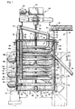
- kettle design substantially teardrop-shaped in cross section which permits an elongated initial straight section for the respective immersion burner tube assemblies.
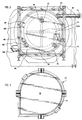
- the kettle design could instead be of a circular cross section design, with exteriorly-mounted burner boxes.
- overflow discharge tube 38 connects with a suitable outlet tube 44.
- a kettle discharge connector or dump gate 46 is mounted at the lower edge of kettle shell 24 (see right lower section thereof in FIG. 1) to permit, when desired, discharge of the entire contents of the kettle 22. This can be either through a material discharge tube or into an associated existing hot pit structure (neither shown).
- the kettle apparatus 20 of the present invention operates at a substantially reduced external temperature compared to those of prior art designs.
- prior art refractory-type kettle structures had to withstand significant elevated operating temperatures, such as 1093° C - 1316° C (2,000°-2,400° F).
- the kettle apparatus 20 of the present invention since the calcining heat is applied internally within the contents via the immersion tube burner coils 74, 92, and 108, the kettle 22 need only retain, not heat, the gypsum 42 being calcined. That is, all of the heat generated by the immersion tube burners is directed via the burner tube coils to the kettle's contents, rather than against the kettle itself.
- Gas-fired immersion tube burners are readily commercially available, such as those made by the following companies: Pillard Combustion (Procedair), of Montreal, Quebec; Eclipse Combustion, of Rockford Illinois; Maxon corporation, of Muncie, Indiana; and Hauck Manufacturing Co., of Lebanon, Pennsylvania.
- the highest capacity gas-fired immersion tube burner is selected, which currently has a capacity limitation of 5.274 x 10 9 joules (5,000,000 BTU).
- Even larger immersion tube burners could be used if commercially available, such as 10.548 x 10 9 joules (10,000,000 BTU) capacity units, however none are presently known.
- the fuel for the burners 70, 90, and 106 could be liquefied petroleum, i.e., LP gas, or natural gas. They are not intended for use with coal or oil, since that type flame would create unwanted interior coatings to the burner tubes 44, 92, 108.
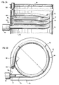
- Each burner tube coil such as the cylindrically-shaped, horizontally-aligned multi-level upper burner tube coil 156, is mounted interiorly of round kettle 152, yet exhausts exteriorly of the kettle 152 and its cover 160 via an exhaust riser tube 162.
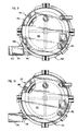
- An initial straight burner tube section 164 connects the upper burner tube coil 156 through the sidewall of the round kettle 152 to the immersion tube burner 154; similarly, straight sections of the remaining ones of the series of underlying burner tube coils (not shown) connect to their respective exteriorly-mounted burners (not shown, except for a partial depiction of the next lower immersion tube burner 155 in FIG. 9).
- the straight sections 164 are formed of stainless steel tubing. Otherwise the remaining structure, components, and cycle operation of the alternate embodiment's kettle apparatus 150 of FIG. 8 are the same as that of the preferred embodiment's kettle apparatus 20.
- the burners 70, 90, and 106 are turned off.
- the empty kettle 22 is then partially filled, i.e., charged, with gypsum 34 via feed screw conveyor 36 until it covers burner tube coil 74.
- the gypsum 34 being introduced into kettle 22 is at ambient temperature, i.e., 16° C - 24° C (60°-75° F), for example. Due to the preferably low profile design of the lowest burner tube assembly 64, the initial calcining zone A of kettle 22 is relatively squat, and thus can be quickly filled for start-up purposes.
- the final charge of material 34 is introduced to allow calcining zone C to fill up and cover over upper burner tube coil 108, which is then energized.
- the three burners 70, 90, and 106 all preferably being run at full capacity, cause the entire contents 42 of kettle 22 to be maintained in the calcining temperature range of approximately 143° C to 154° C (290° to 310° F) and preferably at the preferred calcining process temperature of approximately 149° C (300° F). That temperature can be sensed by well known heat-sensing means, such as thermocouples 146 mounted in each of zones A, B, and C (see FIGS. 1 and 8) of kettle 22.
- the temperature of the calcined material, i.e., stucco, exiting the kettle 22 via discharge cone 40 is approximately 149° C (300° F), while the exhaust gases exiting the riser tubes 80, 92, and 114 is approximately 260° C-316° C (500-600° F).
- a significant advantage of the present method is that more calcined gypsum tonnage output can be achieved in a given kettle space, in contrast to prior art designs. That is, the currently used, refractory-type kettle design of the prior art normally produces approximately 11 tons of stucco per hour. In actuality, the limiting factor in most prior art designs was not how much heat could be applied to the kettle, but what amount of heat the refractory kettle bottom could stand without unwanted, rapid deterioration.
- the residence time is expected to be only 40-45 minutes, i.e., only half the current residence time. It is further believed that the present invention's kettle and burner design could even be operated to result in a material residence time of only 30 minutes, yet still result in a stucco product of sufficient high uniformity and homogeneity, i.e., minimum of under- or over-calcined material.
- a dust collector (not shown) must be used, as connected to dust collector supply pipe 39 (FIG. 1).
- the present invention it works with substantially cleaner exhaust gases. That is, the dust and steam exhaust produced by the present calcining apparatus and method is much cleaner than that of known prior art kettles.
- a dust collector for a kettle made in accordance with the present invention need only handle about 3775.6 x 10 3 cubic cm/second (8,000 CFM) of dust.
- the associated dust collector must be sized to handle approximately 1887.8 x 10 4 cubic cm/second (40,000 CFM) of dust. That improvement alone in the present invention can result in significant energy savings, because of the smaller dust collector. Plus there is less initial capital cost in installing the same, as well as reduced ongoing maintenance costs.
- the present invention's low profile for the initial, lowest burner tube coil permits a shallow material charge during cycle start-up. That, in turn, keeps the load on the agitator motor at a minimum during cycle start-up.
- substantially reduced initial capital costs in constructing the present improved calcining process are anticipated, particularly since no heavily-clad, domed-bottom kettle is required, or any surrounding refractory structure. Further, a shorter building, i.e., kettle housing structure, can be built, due to the lack of any of the prior art's exterior burner structure underlying the kettle.
Landscapes
- Chemical & Material Sciences (AREA)
- Engineering & Computer Science (AREA)
- Organic Chemistry (AREA)
- Chemical Kinetics & Catalysis (AREA)
- Thermal Sciences (AREA)
- Ceramic Engineering (AREA)
- Physics & Mathematics (AREA)
- General Engineering & Computer Science (AREA)
- Mechanical Engineering (AREA)
- Materials Engineering (AREA)
- Structural Engineering (AREA)
- Feeding, Discharge, Calcimining, Fusing, And Gas-Generation Devices (AREA)
- Compounds Of Alkaline-Earth Elements, Aluminum Or Rare-Earth Metals (AREA)
- Compositions Of Oxide Ceramics (AREA)
- Coating By Spraying Or Casting (AREA)
- Heat-Exchange Devices With Radiators And Conduit Assemblies (AREA)
- Combustion Of Fluid Fuel (AREA)
- Furnace Housings, Linings, Walls, And Ceilings (AREA)
Claims (26)
- Procédé de calcination de gypse, comprenant les étapes suivantes :la disposition d'une chaudière de calcination qui comprend au moins un dispositif de chauffage placé à l'intérieur et destiné à faire circuler un fluide chauffé dans une chambre interne de la chaudière sans que le fluide chauffé puisse être au contact du contenu de la chaudière, et que le fluide chauffé soit évacué à l'extérieur de la chaudière et donne pratiquement la totalité de la chaleur nécessaire à la calcination du contenu de la chaudière,l'alimentation de la chaudière en matériau broyé à base de gypse jusqu'à ce que le dispositif de chauffage soit recouvert, puisla circulation du fluide chauffé dans le dispositif de chauffage afin que le matériau de gypse placé dans la chaudière soit chauffé à une température de calcination comprise entre environ 143 et 154 °C (290 à 310 °F), puisl'introduction d'une plus grande quantité du matériau de gypse dans la chaudière afin que le gypse totalement calciné présent dans la chaudière déborde vers un dispositif de récupération destiné à recevoir le gypse totalement calciné provenant de la chaudière.
- Procédé selon la revendication 1, dans lequel l'étape de disposition d'une chaudière de calcination comprend la disposition de plusieurs zones de calcination, chaque zone ayant son propre dispositif de chauffage placé à l'intérieur.
- Procédé selon la revendication 1, comprenant en outre les étapes suivantes :la disposition d'une chaudière de calcination comprenant plusieurs zones de calcination qui comprennent au moins une zone inférieure de calcination et une zone supérieure de calcination, les zones de calcination comprenant respectivement un serpentin de tube de brûleur inférieur et un serpentin de tube de brûleur supérieur,l'alimentation de la chaudière en une charge initiale de matériau broyé de gypse jusqu'à ce que le serpentin de tube de brûleur inférieur soit pratiquement couvert, puisla circulation d'un fluide chauffé dans le serpentin de tube de brûleur inférieur afin que la charge initiale de gypse soit chauffée, puislorsque la charge initiale de gypse atteint une température comprise entre environ 143 et 154 °C (290 à 310 °F), la transmission d'une seconde charge de matériau broyé de gypse dans la chaudière jusqu'à ce que le serpentin de tube de brûleur supérieur soit pratiquement recouvert, puisla circulation d'un fluide de chauffage dans le serpentin de tube de brûleur supérieur afin que toute la charge de gypse atteigne une température comprise entre environ 143 et 149 °C (290 à 300 °F), puisle maintien de la température du gypse dans la chaudière à une valeur comprise entre environ 143 et 154 °C (290 à 310 °F), avec introduction d'une plus grande quantité de matériau de gypse dans la chaudière afin que le gypse totalement calciné dans la chaudière déborde dans un dispositif de récupération destiné à recevoir le gypse totalement calciné de la chaudière, avec création d'une opération continue de calcination.
- Procédé selon la revendication 3, dans lequel les étapes de circulation d'un fluide chauffé dans les serpentins de tube de brûleur comprennent la circulation de gaz chauds dans les serpentins de tube de brûleur.
- Procédé selon la revendication 4, comprenant en outre une étape d'évacuation des gaz chauds des serpentins respectifs de tube de brûleur à l'extérieur de la chaudière.
- Procédé selon la revendication 5, comprenant l'étape supplémentaire de recyclage d'une partie des gaz évacués par la cheminée commune d'évacuation, et la recirculation des gaz d'échappement retirés dans le gypse à l'intérieur de la chaudière afin que le gypse subisse un chauffage supplémentaire.
- Procédé selon la revendication 6, dans lequel l'étape de recirculation des gaz d'échappement évacués comprend l'introduction des gaz d'échappement évacués en position pratiquement adjacente au fond de la chaudière.
- Procédé selon la revendication 3, dans lequel le fluide chaud comprend des gaz chauds de combustion ou une huile ou de la vapeur d'eau chauffée.
- Procédé selon la revendication 3, comprenant l'étape supplémentaire de mélange du gypse à l'intérieur de la chaudière pendant l'étape de maintien de la température du gypse à une valeur comprise entre environ 143 et 154 °C (290 à 310 °F).
- Procédé selon la revendication 9, dans lequel l'étape de mélange comprend en outre le mélange du gypse par aération du gypse à l'intérieur de la chaudière.
- Appareil destiné à la calcination continue du gypse sans double enveloppe réfractaire ni caisson ou revêtement réfractaire, l'appareil comprenant :une chaudière possédant une enveloppe et un fond qui délimitent ensemble une chambre intérieure destinée à contenir le matériau de gypse placé à l'intérieur, etun dispositif de chauffage placé pratiquement à l'intérieur de la chaudière et destiné à faire circuler un fluide chaud dans la chambre interne de la chaudière sans permettre le contact du fluide chaud avec le matériau de gypse contenu dans la chaudière, le dispositif de chauffage assurant l'évacuation vers l'extérieur de la chaudière et étant destiné à chauffer pratiquement l'ensemble du contenu de la chaudière à une température prédéterminée de calcination,un dispositif de récupération du matériau calciné de gypse, etun dispositif de charge continue du gypse broyé dans la chaudière.
- Appareil selon la revendication 11, dans lequel la température prédéterminée de calcination est comprise entre environ 143 et 154 °C (290 à 310 °F) et de préférence est de l'ordre de 149 °C (300 °F).
- Appareil selon la revendication 11, dans lequel le dispositif de chauffage comporte au moins un serpentin de tube de brûleur disposé dans la chambre interne de la chaudière et ayant une sortie disposée à l'extérieur de la chaudière afin que le fluide chaud soit évacué à l'extérieur de la chaudière.
- Appareil selon la revendication 13, comprenant au moins un serpentin supplémentaire de tube de brûleur, si bien que les serpentins respectifs de tube de brûleur assurent un transfert de chaleur étagé au matériau de gypse qui circule dans la chaudière.
- Appareil selon la revendication 11, dans lequel la chaudière contient plusieurs zones de calcination qui comportent chacune un serpentin de tube de brûleur placé dans la chambre interne de la chaudière et une source de chaleur disposée à l'extérieur de l'enveloppe de la chaudière et destinée à transmettre un fluide chaud aux serpentins de tube de brûleur.
- Appareil selon la revendication 15, dans lequel les zones de calcination comprennent une zone inférieure, une zone intermédiaire et une zone supérieure de calcination qui contiennent respectivement un serpentin inférieur, un serpentin intermédiaire et un serpentin supérieur de tube de brûleur.
- Appareil selon la revendication 16, dans lequel le serpentin inférieur de tube de brûleur est réalisé avec une faible hauteur afin qu'il permette un démarrage rapide de la chaudière.
- Appareil selon la revendication 11, dans lequel la source de chaleur comprend plusieurs brûleurs à tube d'immersion raccordés respectivement à chacun des serpentins de tube de brûleur.
- Appareil selon la revendication 11, dans lequel l'enveloppe de la chaudière a une configuration de forme pratiquement cylindrique.
- Appareil selon la revendication 18, dans lequel les brûleurs à tube d'immersion sont raccordés respectivement à des parties rectilignes initiales de tube de chacun des serpentins inférieur, intermédiaire et supérieur de tube de brûleur, les tronçons rectilignes initiaux de tube dépassant à l'extérieur de l'enveloppe de la chaudière.
- Appareil selon la revendication 11, dans lequel le fluide chauffé est choisi parmi de l'huile chaude, de la vapeur d'eau chaude et des gaz chauds de combustion.
- Appareil selon la revendication 16, dans lequel chacun des serpentins inférieur, intermédiaire et supérieur de tube de brûleur est raccordé respectivement à des conduites d'échappement qui s'étendent respectivement à l'extérieur de la chambre de la chaudière et qui sont toutes raccordées à une cheminée commune d'évacuation.
- Appareil selon la revendication 22, dans lequel un dispositif de recyclage est raccordé à la cheminée commune d'évacuation pour l'extraction d'une partie du fluide chauffé de la cheminée commune d'évacuation et la recirculation du fluide chaud dans la chambre de la chaudière.
- Appareil selon la revendication 11, dans lequel le dispositif de mélange est placé dans la chambre de la chaudière et est destiné à mélanger le matériau de gypse placé à l'intérieur.
- Appareil selon la revendication 24, dans lequel le dispositif de mélange comporte en outre un dispositif d'aération placé près du fond de la chaudière et destiné à aérer le matériau de gypse placé dans la chambre de la chaudière.
- Appareil selon la revendication 15, dans lequel chacun des serpentins respectifs de tube de brûleur est aligné en direction pratiquement horizontale par rapport à la chaudière.
Applications Claiming Priority (3)
| Application Number | Priority Date | Filing Date | Title |
|---|---|---|---|
| US08/382,612 US5743954A (en) | 1995-02-02 | 1995-02-02 | Method for continuous refractoryless calcining of gypsum |
| US382612 | 1995-02-02 | ||
| PCT/US1996/001631 WO1996023741A1 (fr) | 1995-02-02 | 1996-02-01 | Procede et dispositif de calcination continue de gypse, sans structure refractaire |
Publications (2)
| Publication Number | Publication Date |
|---|---|
| EP0807090A1 EP0807090A1 (fr) | 1997-11-19 |
| EP0807090B1 true EP0807090B1 (fr) | 1999-08-18 |
Family
ID=23509725
Family Applications (1)
| Application Number | Title | Priority Date | Filing Date |
|---|---|---|---|
| EP96904580A Expired - Lifetime EP0807090B1 (fr) | 1995-02-02 | 1996-02-01 | Procede et dispositif de calcination continue de gypse, sans structure refractaire |
Country Status (11)
| Country | Link |
|---|---|
| US (2) | US5743954A (fr) |
| EP (1) | EP0807090B1 (fr) |
| JP (1) | JP4280303B2 (fr) |
| AT (1) | ATE183485T1 (fr) |
| CA (1) | CA2212208C (fr) |
| DE (1) | DE69603832T2 (fr) |
| DK (1) | DK0807090T3 (fr) |
| ES (1) | ES2134594T3 (fr) |
| GR (1) | GR3031689T3 (fr) |
| PL (1) | PL181194B1 (fr) |
| WO (1) | WO1996023741A1 (fr) |
Families Citing this family (14)
| Publication number | Priority date | Publication date | Assignee | Title |
|---|---|---|---|---|
| US5743728A (en) * | 1995-08-15 | 1998-04-28 | Usg Corporation | Method and system for multi-stage calcining of gypsum to produce an anhydrite product |
| US20050083173A1 (en) * | 2003-10-20 | 2005-04-21 | Konupek Ingrid H. | Locking remote control |
| ES2619124T3 (es) * | 2004-02-27 | 2017-06-23 | United States Gypsum Company | Horno sin refractariedad de alta eficiencia para calcinar yeso y método para ello |
| US7434980B2 (en) * | 2004-02-27 | 2008-10-14 | United States Gypsum Company | Swinging agitator for a gypsum calcining apparatus and the like |
| US7121713B2 (en) * | 2004-02-27 | 2006-10-17 | United States Gypsum Company | Swinging agitator for a gypsum calcining apparatus and the like |
| US7175426B2 (en) * | 2004-02-27 | 2007-02-13 | United States Gypsum Company | High efficiency refractoryless kettle |
| US7100427B2 (en) * | 2004-05-07 | 2006-09-05 | Sensicore, Inc. | Multi-sensor system for fluid monitoring with selective exposure of sensors |
| US8388926B2 (en) | 2006-01-13 | 2013-03-05 | Certainteed Gypsum, Inc. | System and method for the production of gypsum using heat recovery |
| HUE029576T2 (en) * | 2006-01-13 | 2017-03-28 | Certainteed Gypsum Inc | System and method for producing alpha-type gypsum using heat recovery |
| US7933852B2 (en) * | 2006-06-09 | 2011-04-26 | Scientific Learning Corporation | Method and apparatus for developing cognitive skills |
| US7588634B2 (en) * | 2006-09-20 | 2009-09-15 | United States Gypsum Company | Process for manufacturing ultra low consistency alpha- and beta- blend stucco |
| US20090208392A1 (en) * | 2008-02-14 | 2009-08-20 | Georgia-Pacific Gypsum, Llc | Process for producing alpha-hemihydrate gypsum |
| US20140113241A1 (en) * | 2012-10-22 | 2014-04-24 | United States Gypsum Company | Calcining kettle |
| US11046611B2 (en) * | 2018-04-10 | 2021-06-29 | Tru-Flow Systems, Inc. | Calcining kettle, calcining system, and method |
Family Cites Families (42)
| Publication number | Priority date | Publication date | Assignee | Title |
|---|---|---|---|---|
| DE169737C (fr) * | ||||
| US1446863A (en) * | 1921-05-26 | 1923-02-27 | Sheldon E Townley | Gypsum calcining apparatus |
| US2261872A (en) * | 1938-06-08 | 1941-11-04 | Anna W Choate | Continuous process for making reacted plaster |
| US2274256A (en) * | 1939-08-24 | 1942-02-24 | Alcorn Comb Co | Fluid heater |
| US3236509A (en) * | 1961-11-13 | 1966-02-22 | British Plaster Board Holdings | Process and apparatus for continuous calcining of powdered gypsum rock |
| NL285104A (fr) * | 1961-11-13 | |||
| GB1198807A (en) * | 1963-12-03 | 1970-07-15 | Ici Ltd | Continuous process for the production of calcium sulphate alpha-hemihydrate from gypsum |
| US3307840A (en) * | 1964-01-14 | 1967-03-07 | Georgia Pacific Corp | Continuous calcination of gypsum |
| US3307915A (en) * | 1964-01-22 | 1967-03-07 | Georgia Pacific Corp | Apparatus for continuous calcination of gypsum |
| US3479143A (en) * | 1964-07-13 | 1969-11-18 | Girdler Corp | Means for conducting endothermic catalytic reactions,including electrical heating means |
| GB1087549A (en) * | 1964-12-29 | 1967-10-18 | Bpb Industries Ltd | Process of calcining gypsum |
| DE1285936B (de) * | 1965-01-12 | 1968-12-19 | Bpb Ind | Verfahren zum kontinuierlichen Brennen von Gips |
| US3376599A (en) * | 1965-10-15 | 1968-04-09 | Singer Safety Products Inc | Mounting arrangement for insulated bulkhead or the like |
| US3378246A (en) * | 1965-11-15 | 1968-04-16 | United States Gypsum Co | Calcining kettle discharge apparatus |
| US3669435A (en) * | 1970-02-26 | 1972-06-13 | American Optical Corp | All-ceramic glass making system |
| US3901645A (en) * | 1971-04-07 | 1975-08-26 | Universal Kettle Company Inc | Calcining kettle and system |
| US3871829A (en) * | 1972-10-20 | 1975-03-18 | Gen Electric | Calciner with baffle means |
| GB1488665A (en) * | 1973-11-27 | 1977-10-12 | Bpb Industries Ltd | Calcining calcium sulphate dihydrate |
| US4176157A (en) * | 1974-11-14 | 1979-11-27 | Bpb Industries Limited | Calcining calcium sulphate dihydrate |
| US4113836A (en) * | 1976-10-29 | 1978-09-12 | National Gypsum Company | Continuous gypsum calcination process and kettle therefor |
| DE2705710C3 (de) * | 1977-02-11 | 1980-06-04 | Kloeckner-Humboldt-Deutz Ag, 5000 Koeln | Gegenstrombrennverfahren zur Erzeugung von Branntkalk und Schachtofen zur Durchfuhrung des Verfahrens |
| US4117070A (en) * | 1977-03-14 | 1978-09-26 | United States Gypsum Company | Process for preparing calcined gypsum |
| US4161390A (en) * | 1977-06-16 | 1979-07-17 | United States Gypsum Company | Calcining kettle having multi-pass heating system |
| DE2754844A1 (de) * | 1977-12-09 | 1979-06-13 | Kloeckner Humboldt Deutz Ag | Etagenofen |
| US4238283A (en) * | 1978-04-24 | 1980-12-09 | Philip Morris Incorporated | Post-treatment of humic acid-dyed paper |
| US4188186A (en) * | 1978-06-22 | 1980-02-12 | Combustion Engineering, Inc. | Automatic calcining kettle |
| US4215981A (en) * | 1978-10-12 | 1980-08-05 | Nichols Engineering & Research Corp. | Heating or combustion apparatus and method |
| NL185896C (nl) * | 1979-01-08 | 1990-08-16 | Bpb Industries Ltd | Inrichting voor het met warmte behandelen van een korrelvormig materiaal. |
| US4238238A (en) * | 1979-08-15 | 1980-12-09 | United States Gypsum Company | Calcining kettle having means for returning stack exhaust gas to calcining mixture |
| EP0044005B1 (fr) * | 1980-07-14 | 1984-09-26 | HIS Handels- und Industriebedarf GmbH | Préparation de gypse hémihydraté par usage de chaleur d'échappement, d'acide sulfurique aqueux et de sels sulfuriques |
| DE3248502A1 (de) * | 1982-12-29 | 1984-07-05 | Basf Ag, 6700 Ludwigshafen | Verfahren zur temperierung einer in einem rohrreaktor in form eines festbettes angeordneten schuettung und eine anordnung zur durchfuehrung des verfahrens |
| US4533528A (en) * | 1983-07-15 | 1985-08-06 | United States Gypsum Company | Process for continuously calcining gypsum to low dispersed consistency stucco |
| US4522587A (en) * | 1984-01-23 | 1985-06-11 | Hy-Way Heat Systems, Inc. | Rotating melter |
| US4569831A (en) * | 1985-04-01 | 1986-02-11 | Fuller Company | Process and apparatus for calcining gypsum |
| US4744961A (en) * | 1985-04-25 | 1988-05-17 | United States Gypsum Company | Submerged combustion calcination |
| GB2185419B (en) * | 1986-01-07 | 1990-04-18 | Bpb Industries Plc | Improvements in calcination apparatus |
| US5169444A (en) * | 1986-02-20 | 1992-12-08 | Gebruder Knauf Westdeutsche Gipswerke Kg | Process for preparing calcium sulfate anhydrite |
| US4744963A (en) * | 1986-08-14 | 1988-05-17 | United States Gypsum Company | Highly efficient calcination of gypsum to hemihydrate |
| GB8625964D0 (en) * | 1986-10-30 | 1986-12-03 | Bpb Industries Plc | Calcination apparatus |
| US5007825A (en) * | 1990-05-21 | 1991-04-16 | Williams Robert M | Heat reclamation apparatus |
| US5139749A (en) * | 1990-06-22 | 1992-08-18 | Tas, Inc. | Fluidized calcining process |
| DE9319041U1 (de) * | 1993-12-11 | 1994-02-24 | Babcock-BSH AG vormals Büttner-Schilde-Haas AG, 47829 Krefeld | Drehtrommel |
-
1995
- 1995-02-02 US US08/382,612 patent/US5743954A/en not_active Expired - Lifetime
-
1996
- 1996-02-01 ES ES96904580T patent/ES2134594T3/es not_active Expired - Lifetime
- 1996-02-01 JP JP52378796A patent/JP4280303B2/ja not_active Expired - Fee Related
- 1996-02-01 WO PCT/US1996/001631 patent/WO1996023741A1/fr not_active Ceased
- 1996-02-01 EP EP96904580A patent/EP0807090B1/fr not_active Expired - Lifetime
- 1996-02-01 DK DK96904580T patent/DK0807090T3/da active
- 1996-02-01 AT AT96904580T patent/ATE183485T1/de active
- 1996-02-01 DE DE69603832T patent/DE69603832T2/de not_active Expired - Lifetime
- 1996-02-01 CA CA002212208A patent/CA2212208C/fr not_active Expired - Lifetime
- 1996-02-01 PL PL96321760A patent/PL181194B1/pl not_active IP Right Cessation
-
1997
- 1997-12-23 US US08/997,205 patent/US5927968A/en not_active Expired - Lifetime
-
1999
- 1999-10-29 GR GR990402780T patent/GR3031689T3/el unknown
Also Published As
| Publication number | Publication date |
|---|---|
| JPH10513428A (ja) | 1998-12-22 |
| ES2134594T3 (es) | 1999-10-01 |
| JP4280303B2 (ja) | 2009-06-17 |
| GR3031689T3 (en) | 2000-02-29 |
| US5743954A (en) | 1998-04-28 |
| PL181194B1 (pl) | 2001-06-29 |
| CA2212208C (fr) | 2004-12-14 |
| MX9705903A (es) | 1998-06-30 |
| US5927968A (en) | 1999-07-27 |
| EP0807090A1 (fr) | 1997-11-19 |
| DE69603832T2 (de) | 2000-03-09 |
| DE69603832D1 (de) | 1999-09-23 |
| ATE183485T1 (de) | 1999-09-15 |
| CA2212208A1 (fr) | 1996-08-08 |
| DK0807090T3 (da) | 1999-12-06 |
| PL321760A1 (en) | 1997-12-22 |
| WO1996023741A1 (fr) | 1996-08-08 |
Similar Documents
| Publication | Publication Date | Title |
|---|---|---|
| US5743954A (en) | Method for continuous refractoryless calcining of gypsum | |
| US5954497A (en) | Method for multi-stage calcining of gypsum to produce an anhydrite product | |
| US5606965A (en) | Submerged combustion system | |
| CA1141157A (fr) | Methode et installation de calcination | |
| US4672899A (en) | Preburning plant for burning solid fuel materials having a high ash contents | |
| US4744963A (en) | Highly efficient calcination of gypsum to hemihydrate | |
| US4188186A (en) | Automatic calcining kettle | |
| US3357377A (en) | Combustion of organic waste material | |
| KR100283682B1 (ko) | 열풍건조장치 | |
| US5097773A (en) | Multi-sided watercooled rotary combustor | |
| US3218995A (en) | Sludge drying and incineration apparatus for industrial waste-water treatment | |
| MXPA97005903A (en) | Method and apparatus for the calcination of sinrefractar gypsum | |
| CN2434305Y (zh) | 活性炭立式活化炉 | |
| US11046611B2 (en) | Calcining kettle, calcining system, and method | |
| US647432A (en) | Apparatus for burning garbage or other refuse matter. | |
| US3561347A (en) | Cooker for grain or the like having preheater | |
| EP0953628B1 (fr) | Composition de combustible qui brûle instantanément et méthode de brûler | |
| RU2145696C1 (ru) | Шахтный теплообменник вращающейся печи | |
| US3939784A (en) | Fuel conduit | |
| CN107101367A (zh) | 一种热水锅炉 | |
| EP0434172B1 (fr) | Procédé et dispositif pour la fabrication de produits enrobés bitumineux | |
| PL204961B1 (pl) | Zespół stabilizatora do ciągłej transformacji termokatalitycznej odpadów z tworzyw sztucznych poliolefinowych | |
| AU2252400A (en) | Installation for thermolysis processing of waste with fumes that have a low freeoxygen content | |
| Fisher et al. | SOME NEW DEVELOPMENTS IN FLUIDISED-BED SHELL BOILERS | |
| PL227065B1 (pl) | Sposób fermentacji frakcji organicznej odpadów komunalnych oraz reaktor kompaktowy dofermentacji tych odpadów |
Legal Events
| Date | Code | Title | Description |
|---|---|---|---|
| PUAI | Public reference made under article 153(3) epc to a published international application that has entered the european phase |
Free format text: ORIGINAL CODE: 0009012 |
|
| 17P | Request for examination filed |
Effective date: 19970827 |
|
| AK | Designated contracting states |
Kind code of ref document: A1 Designated state(s): AT BE DE DK ES FR GB GR IE IT LU NL SE |
|
| 17Q | First examination report despatched |
Effective date: 19971222 |
|
| GRAG | Despatch of communication of intention to grant |
Free format text: ORIGINAL CODE: EPIDOS AGRA |
|
| GRAG | Despatch of communication of intention to grant |
Free format text: ORIGINAL CODE: EPIDOS AGRA |
|
| GRAH | Despatch of communication of intention to grant a patent |
Free format text: ORIGINAL CODE: EPIDOS IGRA |
|
| GRAG | Despatch of communication of intention to grant |
Free format text: ORIGINAL CODE: EPIDOS AGRA |
|
| GRAH | Despatch of communication of intention to grant a patent |
Free format text: ORIGINAL CODE: EPIDOS IGRA |
|
| GRAA | (expected) grant |
Free format text: ORIGINAL CODE: 0009210 |
|
| AK | Designated contracting states |
Kind code of ref document: B1 Designated state(s): AT BE DE DK ES FR GB GR IE IT LU NL SE |
|
| REF | Corresponds to: |
Ref document number: 183485 Country of ref document: AT Date of ref document: 19990915 Kind code of ref document: T |
|
| REF | Corresponds to: |
Ref document number: 69603832 Country of ref document: DE Date of ref document: 19990923 |
|
| REG | Reference to a national code |
Ref country code: ES Ref legal event code: FG2A Ref document number: 2134594 Country of ref document: ES Kind code of ref document: T3 |
|
| REG | Reference to a national code |
Ref country code: IE Ref legal event code: FG4D |
|
| ITF | It: translation for a ep patent filed | ||
| ET | Fr: translation filed | ||
| REG | Reference to a national code |
Ref country code: DK Ref legal event code: T3 |
|
| PLBE | No opposition filed within time limit |
Free format text: ORIGINAL CODE: 0009261 |
|
| STAA | Information on the status of an ep patent application or granted ep patent |
Free format text: STATUS: NO OPPOSITION FILED WITHIN TIME LIMIT |
|
| 26N | No opposition filed | ||
| REG | Reference to a national code |
Ref country code: GB Ref legal event code: IF02 |
|
| PGFP | Annual fee paid to national office [announced via postgrant information from national office to epo] |
Ref country code: LU Payment date: 20100312 Year of fee payment: 15 Ref country code: IE Payment date: 20100224 Year of fee payment: 15 |
|
| PGFP | Annual fee paid to national office [announced via postgrant information from national office to epo] |
Ref country code: DK Payment date: 20110224 Year of fee payment: 16 |
|
| PGFP | Annual fee paid to national office [announced via postgrant information from national office to epo] |
Ref country code: SE Payment date: 20110225 Year of fee payment: 16 Ref country code: AT Payment date: 20110119 Year of fee payment: 16 Ref country code: NL Payment date: 20110228 Year of fee payment: 16 |
|
| PGFP | Annual fee paid to national office [announced via postgrant information from national office to epo] |
Ref country code: GR Payment date: 20110228 Year of fee payment: 16 |
|
| PGFP | Annual fee paid to national office [announced via postgrant information from national office to epo] |
Ref country code: ES Payment date: 20110224 Year of fee payment: 16 Ref country code: BE Payment date: 20110224 Year of fee payment: 16 |
|
| REG | Reference to a national code |
Ref country code: IE Ref legal event code: MM4A |
|
| PG25 | Lapsed in a contracting state [announced via postgrant information from national office to epo] |
Ref country code: IE Free format text: LAPSE BECAUSE OF NON-PAYMENT OF DUE FEES Effective date: 20110201 |
|
| BERE | Be: lapsed |
Owner name: *UNITED STATES GYPSUM CY Effective date: 20120228 |
|
| REG | Reference to a national code |
Ref country code: NL Ref legal event code: V1 Effective date: 20120901 |
|
| REG | Reference to a national code |
Ref country code: GR Ref legal event code: ML Ref document number: 990402780 Country of ref document: GR Effective date: 20120905 |
|
| PG25 | Lapsed in a contracting state [announced via postgrant information from national office to epo] |
Ref country code: SE Free format text: LAPSE BECAUSE OF NON-PAYMENT OF DUE FEES Effective date: 20120202 |
|
| REG | Reference to a national code |
Ref country code: DK Ref legal event code: EBP |
|
| PG25 | Lapsed in a contracting state [announced via postgrant information from national office to epo] |
Ref country code: GR Free format text: LAPSE BECAUSE OF NON-PAYMENT OF DUE FEES Effective date: 20120905 |
|
| REG | Reference to a national code |
Ref country code: AT Ref legal event code: MM01 Ref document number: 183485 Country of ref document: AT Kind code of ref document: T Effective date: 20120201 |
|
| PG25 | Lapsed in a contracting state [announced via postgrant information from national office to epo] |
Ref country code: BE Free format text: LAPSE BECAUSE OF NON-PAYMENT OF DUE FEES Effective date: 20120228 |
|
| PG25 | Lapsed in a contracting state [announced via postgrant information from national office to epo] |
Ref country code: AT Free format text: LAPSE BECAUSE OF NON-PAYMENT OF DUE FEES Effective date: 20120201 Ref country code: NL Free format text: LAPSE BECAUSE OF NON-PAYMENT OF DUE FEES Effective date: 20120901 |
|
| PG25 | Lapsed in a contracting state [announced via postgrant information from national office to epo] |
Ref country code: LU Free format text: LAPSE BECAUSE OF NON-PAYMENT OF DUE FEES Effective date: 20110201 |
|
| REG | Reference to a national code |
Ref country code: ES Ref legal event code: FD2A Effective date: 20130708 |
|
| PG25 | Lapsed in a contracting state [announced via postgrant information from national office to epo] |
Ref country code: ES Free format text: LAPSE BECAUSE OF NON-PAYMENT OF DUE FEES Effective date: 20120202 |
|
| PG25 | Lapsed in a contracting state [announced via postgrant information from national office to epo] |
Ref country code: DK Free format text: LAPSE BECAUSE OF NON-PAYMENT OF DUE FEES Effective date: 20120229 |
|
| REG | Reference to a national code |
Ref country code: FR Ref legal event code: PLFP Year of fee payment: 20 |
|
| PGFP | Annual fee paid to national office [announced via postgrant information from national office to epo] |
Ref country code: IT Payment date: 20150225 Year of fee payment: 20 Ref country code: DE Payment date: 20150226 Year of fee payment: 20 |
|
| PGFP | Annual fee paid to national office [announced via postgrant information from national office to epo] |
Ref country code: GB Payment date: 20150226 Year of fee payment: 20 Ref country code: FR Payment date: 20150217 Year of fee payment: 20 |
|
| REG | Reference to a national code |
Ref country code: DE Ref legal event code: R071 Ref document number: 69603832 Country of ref document: DE |
|
| REG | Reference to a national code |
Ref country code: GB Ref legal event code: PE20 Expiry date: 20160131 |
|
| PG25 | Lapsed in a contracting state [announced via postgrant information from national office to epo] |
Ref country code: GB Free format text: LAPSE BECAUSE OF EXPIRATION OF PROTECTION Effective date: 20160131 |