EP0807000B1 - Gasverteilungsvorrichtung für flämmgeräte - Google Patents
Gasverteilungsvorrichtung für flämmgeräte Download PDFInfo
- Publication number
- EP0807000B1 EP0807000B1 EP96904476A EP96904476A EP0807000B1 EP 0807000 B1 EP0807000 B1 EP 0807000B1 EP 96904476 A EP96904476 A EP 96904476A EP 96904476 A EP96904476 A EP 96904476A EP 0807000 B1 EP0807000 B1 EP 0807000B1
- Authority
- EP
- European Patent Office
- Prior art keywords
- bore
- gas
- piston
- scarfing
- chamber
- Prior art date
- Legal status (The legal status is an assumption and is not a legal conclusion. Google has not performed a legal analysis and makes no representation as to the accuracy of the status listed.)
- Expired - Lifetime
Links
Images


Classifications
-
- B—PERFORMING OPERATIONS; TRANSPORTING
- B23—MACHINE TOOLS; METAL-WORKING NOT OTHERWISE PROVIDED FOR
- B23K—SOLDERING OR UNSOLDERING; WELDING; CLADDING OR PLATING BY SOLDERING OR WELDING; CUTTING BY APPLYING HEAT LOCALLY, e.g. FLAME CUTTING; WORKING BY LASER BEAM
- B23K7/00—Cutting, scarfing, or desurfacing by applying flames
- B23K7/06—Machines, apparatus, or equipment specially designed for scarfing or desurfacing
Definitions
- This invention relates to an apparatus for thermochemically scarfing a metal workpiece, and more particularly, to a gas distribution manifold for a scarfing apparatus and which is able to achieve a uniformly scarfed surface on metal workpieces of non-uniform temperature and/or metallurgical quality.
- Hot steel slabs are commonly conditioned by positioning scarfing units along the top, bottom, and side surfaces of an advancing slab to eliminate surface defects such as cracks, seams, and slag intrusions.
- One conventional scarfing apparatus includes top, bottom, and opposite side scarfing units that are mounted across the width and end portions of a support, to concurrently scarf all sides of the slab as the slab is passed therebetween.
- the top, side, and bottom scarfing units each include a gas distribution manifold, which receives and distributes oxygen, fuel gas, and cooling water to a number of scarfing units which are positioned in a side by side arrangement along the front of the manifold.
- each scarfing unit comprises upper and lower preheat blocks which are spaced from each other to define an oxygen scarfing slot between the two blocks and through which a quantity of oxygen is discharged onto the slab surface to enable scarfing.
- the workpiece has a temperature variation, or a variation in metallurgical quality, across its width. More particularly, the temperature near one or both edges of the advancing workpiece is often lower than the temperature in the middle of the workpiece, and in this event the metal removal is reduced near the low temperature edges. Such a result is also possible where there is a variation in the metallurgical quality adjacent the side edges of the workpiece.
- An apparatus according to the preamble of claim 1 and a manifold according to the preamble of claim 4 are known for example, from the closest prior art documents US-A-5 333 841 and US-A-5 358 221.
- an apparatus according to claim 1 and a gas distribution manifold according to claim 4 for a scarfing apparatus which comprises a block of metallic material including an elongate mounting surface formed on one face thereof and which defines a longitudinal direction. At least one gas distribution bore is formed in the block which extends parallel to the longitudinal direction and which defines a first end and an opposite second end, and a plurality of longitudinally spaced apart drillings extending radially from the bore to the mounting surface.
- a partition is fixed in the bore at a location adjacent but spaced from the first end so as to define a first chamber in the bore between the first end and the partition.
- a piston is slidably mounted in the bore at a location between partition and second end so as to define a second chamber in the bore between the partition and piston.
- the piston includes a pair of longitudinally spaced apart piston heads defining a third chamber in the bore between the piston heads.
- a first gas inlet communicates with the first chamber
- a second gas inlet communicates with the second chamber
- a third gas inlet communicates with the third chamber.
- the third gas inlet comprises a tubular piston rod connected to the piston heads, and a plurality of openings in the tubular piston rod between said piston heads.
- the metal scarfing apparatus of the present invention further comprises control means operatively connected to each of the three gas inlets for permitting the pressure of the gas delivered to each of the gas inlets to be separately controlled.
- control means operatively connected to each of the three gas inlets for permitting the pressure of the gas delivered to each of the gas inlets to be separately controlled.
- the apparatus of the invention further comprises a plurality of scarfing units mounted in a side by side arrangement along the mounting surface of the manifold, the scarfing units each including a rear face contiguous to the mounting surface and a forwardly facing front face. Also, a plurality of ducts extend through each of scarfing units from the rear face to the front face thereof, with the ducts communicating with respective ones of the drillings at the interface of the mounting surface and the rear face.
- a gas may be delivered from the three chambers of the bore to the ducts of the scarfing units and discharged from the front faces thereof along a variable longitudinal length dimension by control of the longitudinal position of piston.
- Figure 1 illustrates a scarfing apparatus 10 which is adapted to embody the features of the present invention and which is positioned to scarf the upper surface of a workpiece, which typically comprises a steel slab S .
- a workpiece typically comprises a steel slab S .
- an overall scarfing system typically comprises similar scarfing apparatuses positioned above and below the plane of the steel slab S to be scarfed, with the upper and lower scarfing apparatuses extending across the full width of the slab S .
- side scarfing apparatuses of like design are positioned so as to scarf the sides of a slab S .
- the slab S normally is positioned on a movable roll table (not shown) so as to be fed through the rectangular configuration defined by the several scarfing apparatuses, and in the direction of the arrow 11 .
- the apparatus 10 includes a gas distribution manifold 12 , typically formed from a block of bronze or copper material, and the block defines a generally planar front mounting surface 13 which defines a longitudinal direction which is perpendicular to the plane of Figure 1.
- a plurality of scarfing units 14 are mounted in a side by side arrangement along the longitudinal direction of the mounting surface 13 as seen in Figures 2-5.
- Each scarfing unit 14 comprises an upper preheat block assembly 15 and a lower preheat block assembly 16 .
- the block of the manifold 12 also includes a pair of internal fuel gas lines 18 and 19 , a pair of oxygen lines 20 and 21 , inlet and outlet water lines 22 and 23 respectively leading to the upper block assembly, and inlet and outlet water lines 22' and 23' respectively, leading to the lower block assembly 16 . All of these lines communicate with the front surface 13 for the purposes described below.
- a riding shoe 30 is mounted to the manifold and head assembly 12 along the underside of the lower preheat block 16 .
- the riding shoe 30 includes a lower surface 31 having slab engaging skids 32 adapted to contact the slab to position the scarfing apparatus 10 a predetermined distance from the steel slabs as further described below.
- the scarfing apparatus 10 is above the slab S , and it will be understood that similar apparatuses are arranged below and at the opposite sides of the slab S .
- the upper preheat block assembly 15 and the lower preheat block assembly 16 are spaced from each other to define an oxygen slot 34 and discharge orifice 35 of predetermined size for receiving a flow of scarfing oxygen from the oxygen line 20 of the manifold and head assembly and discharging the scarfing oxygen through the discharge orifice 35 onto the steel slab S during the scarfing operation.
- the upper preheat block assembly 15 includes a base member 40 , and an extension 41 secured to the base member by bolts 42 and extending forwardly therefrom.
- the base member 40 comprises a block of metallic material, preferably copper, and the rear face of the base member is releasably secured to the front surface 13 of the manifold 12 by means of bolts 43 .
- the extension 41 of the upper preheat block assembly also comprises a block of metallic material, preferably copper, and it includes a plurality of discharge openings 45 which are positioned adjacent to each other in a longitudinal row along the front face and extending rearwardly into the block. Also, a longitudinally extending row of discharge outlets 46 is provided in the front face of the extension, with the row of outlets 46 extending parallel to and above the row of openings 45 .
- a plurality of ducts, generally indicated at 47 communicate with respective ones of the gas and water supply lines 19 , 21-23 at the mounting surface 13 , and extend through the block assembly 15 to the openings 45 and outlets 46 in the front face of the assembly.
- the lower preheat block assembly 16 includes a base member 50 , and an extension 52 secured to the base member 50 and extending forwardly therefrom.
- the base member 50 includes a plurality of parallel ducts 54 , which communicate with a slot 56 which extends longitudinally across the front face of the extension 52 .
- the ducts 54 also communicate with the fuel gas supply line 18 in the gas distribution manifold 12 .
- a plurality of ducts 58 extend through the assembly 16 and communicate with the water lines 22' and 23' for circulating cooling water through the assembly.
- the table (not shown) on which the steel slab S rests is moved into a position in which the scarfing apparatus 10 is positioned over and adjacent an end of the slab.
- the scarfing apparatus preheat fuel gas is then ignited at a low flow rate, and the preheat oxygen is also discharged at a low flow rate.
- the preheat fuel gas flow rate is then increased, and just after the preheat fuel gas flow rate is increased, the oxygen preheat flow is increased, and this flow includes a stabilizing oxygen stream immediately above the preheating gas stream emanating from the discharge outlets.
- the preheated oxygen flow is substantially reduced and the flow of scarfing oxygen is generated through the slot 34 .
- the preheating fuel gas is reduced, and the table holding the steel slab is moved toward the scarfing apparatus.
- the table is initially moved forward at a first relatively slow speed, which is typically about 3 to 4 meters per minute, and after a predetermined period, its speed is increased to the normal scarfing speed, which is about four times as fast as the first speed.
- the flow rate of the oxygen is decreased slightly at the time when the table speed reaches the normal scarfing speed.
- Scarfing then continues, and preferably a stream of fuel gas is concurrently discharged from the slot 56 of the lower block assembly 16 , to facilitate maintenance of the oxidizing reaction. Also, the manifold 12 and its associated upper block assembly 15 , lower preheat block 16 and shoe 30 move so that the skids 32 come into contact with the moving slab S , and the entire apparatus 10 "floats" with the riding skids 32 in contact with the moving slab.
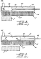
- FIGS 2 and 3 illustrate the prior art system for controlling the operation of the scarfing units 14 as described above, to accommodate workpieces S of varying width. While the illustrated embodiment relates to the delivery of only one of the gases to the scarfing units, it will be understood that similar arrangements may be provided for the second gas and water.
- the gas distribution manifold 12 includes a gas distribution bore 60 in the manifold 12 which extends parallel to the longitudinal direction defined by the mounting surface 13 .
- a plurality of longitudinally spaced apart drillings 62 extend radially from the bore 60 to the mounting surface 13 .
- a gas inlet 64 is connected to the bore 60 adjacent its left end as illustrated, for introducing a gas into the bore 60
- a longitudinally movable piston 66 is mounted in the bore 60 to define a distribution chamber 68 of variable longitudinal length between the left end of the bore and the piston 66 .
- a plurality of scarfing units 14 as described above are mounted in a side-by-side arrangement along the mounting surface 13 , and the scarfing units 14 each include a rear face which is contiguous to the mounting surface and a forwardly facing front face.
- the above described ducts 34 , 47 , 58 extend through each of the scarfing units from the rear face to the front face thereof, and these ducts communicate with respective ones of the drillings 62 at the interface of the mounting surface 13 and the rear faces of the scarfing units.
- a gas may be delivered from the distribution chamber 68 of the bore 60 to the ducts of the scarfing units 14 and discharged from the front faces thereof along a variable longitudinal dimension which is controlled by the longitudinal position of the piston 66 .
- FIG. 3 illustrates that a number of additional scarfing units 14 may be brought into operation by withdrawal of the piston 66 which serves to open additional ones of the drillings 62 to the distribution chamber 68 of the bore 60 , and to thereby accommodate a workpiece of longer width.
- Figures 4 and 5 are similar to Figures 2 and 3 respectively, but illustrate the modifications provided by the present invention.
- the distribution bore 60 includes a fixed partition 70 dividing the same into a first distribution chamber 71 between the left end and the partition, with the chamber 71 being aligned with a first side edge portion or band A of the workpiece, which is of fixed dimension.
- a second or main distribution chamber 72 is defined between the partition 70 and the piston 66' , which is aligned with a central width portion or band B of the workpiece, which is of adjustable dimension.
- the piston 66' includes a pair of longitudinally spaced apart piston heads 74 , 75 which define a third distribution chamber 76 therebetween, which is aligned with the opposite side edge portion or band C of the workpiece, and which is of fixed dimension.
- a first gas inlet 78 communicates with the first distribution chamber 71
- a second gas inlet 79 communicates with the main distribution chamber 72
- a third gas inlet is provided for the third distribution chamber 76 defined between the piston heads 74 , 75 which comprises a tubular piston rod 80 connected to the piston heads and a plurality of openings 81 in the tubular piston rod positioned between the piston heads 74 , 75 .
- the gas supply system includes a gas supply 90 , having a first line 91 leading to a gas flow rate control 92 and then to the first gas inlet 78 .
- a second line 94 leads from the supply 90 to a second separate control 95 , which then leads to the second gas inlet 79 .
- a third line 97 leads to a third separate control 98 , and then to the tubular piston rod 80 and then to the third distribution chamber 76 .
- the depth of scarfing cut may be separately controlled for each of the three width segments of the workpiece which correspond to the three distribution chambers 71 , 72 , 76 , it being understood that a higher gas flow rate onto the surface of the workpiece will result in a deeper scarfing cut.
- the depth of cut for each width segment may be determined by the operator and set by appropriate adjustment of the flow rate controls.
- the settings of the controls are based upon the grade of the steel, its temperature, and metallurgical quality.
- the settings may be adjusted after visually or otherwise monitoring the operation of the apparatus, to tune the overall operation of the process and achieve the desired surface conditions in accordance with the end product quality requirements of the user.
Landscapes
- Engineering & Computer Science (AREA)
- Mechanical Engineering (AREA)
- Gas Burners (AREA)
- Pre-Mixing And Non-Premixing Gas Burner (AREA)
- Crystals, And After-Treatments Of Crystals (AREA)
- Catalysts (AREA)
- Manufacture, Treatment Of Glass Fibers (AREA)
- Waste-Gas Treatment And Other Accessory Devices For Furnaces (AREA)
- Pipeline Systems (AREA)
Claims (8)
- Vorrichtung zum Leiten eines Gasstromes quer über die Breite eines sich bewegenden Metallwerkstückes (S) während eines Flämmvorganges, mit:einer Gasverteilungseinrichtung (12), die ausbildet eine längliche, eine Längsrichtung festlegende Befestigungsfläche (13), in der Einrichtung wenigstens eine parallel zur Längsrichtung verlaufende Gasverteilungsbohrung (60), eine Mehrzahl von in Längsrichtung mit Abstand zueinander angeordnete, radial von der Bohrung zu der Befestigungsfläche verlaufende Durchbohrungen (62), einen Gaseinlaß (80), der in der Nähe eines Endes der Bohrung mit dieser verbunden ist, um Gas in die Bohrung einzuführen, und einen längsbeweglichen Kolben (66'), der in der Bohrung (60) montiert ist, um deren gegenüberliegendes Ende zu schließen und eine Verteilungskammer (68) von variabler Längserstreckung zwischen dem besagten einen Ende und dem Kolben (66') zu bilden,einer Mehrzahl von Flämmeinheiten (14), die in einer Seite-an-Seite-Anordnung längs der Befestigungsfläche befestigt sind, jeweils (14) eine Rückseite nahe der Befestigungsfläche und eine nach vorne gewandte Vorderseite sowie eine Mehrzahl von Kanälen aufweisen, die jede der Flämmeinheiten von der Rückseite bis zu deren Vorderseite durchlaufen und mit jeweils einer der Durchbohrungen (62) an der Grenzfläche der Befestigungsfläche und der Rückseiten in Verbindung stehen, wobei ein Gas aus der Verteilungskammer der Bohrung den Kanälen der Flämmeinheiten zugeführt werden und aus deren Vorderseiten längs einer variablen Längserstreckungsabmessung durch Steuerung der Längsposition des Kolbens ausströmen kann,
dadurch gekennzeichnet, daß die Verteilungsbohrung (60) in eine Mehrzahl von getrennten Verteilungskammern (70-72) unterteilt ist, wobei jede der Kammern einen separaten Gaseinlaß aufweist und die Längserstreckung wenigstens einer der Kammern abhängig von der Längspositionierung des Kolbens (66) ist, so daß das Gas den separaten Kammern unter variierenden Bedingungen zugeführt werden kann, um dadurch ein Variieren der Menge des den Flämmeinheiten zugeführten Gases an ausgewählten Stellen längs der Längsrichtung und quer über die Breite des Werkstückes zu ermöglichen,
wobei in der Verteilungsbohrung (60) eine feststehende Trennwand (70) befestigt ist, die die Bohrung in eine erste Seitenrand-Verteilungskammer (71) zwischen dem besagten einen Ende und der Trennwand sowie in eine Hauptverteilungskammer (72) zwischen der Trennwand und dem Kolben unterteilt, wobei die Bohrung ferner einen ersten Gaseinlaß, der mit der ersten Seitenrand-Verteilungskammer in Verbindung steht, und einen zweiten Gaseinlaß aufweist, der mit der Hauptverteilungskammer in Verbindung steht, und
wobei der Kolben (66') ein Paar in Längsrichtung mit Abstand voneinander angeordnete Kolbenkopfe (74, 75), die eine gegenüberliegende Seitenrand-Verteilungskammer zwischen sich ausbilden, und einen dritten Gaseinlaß aufweist, der min der gegenüberliegenden Seitenrand-Verteilungskammer in Verbindung steht. - Verfahren nach Anspruch 1, bei dem der dritte Gaseinlaß eine rohrförmige Kolbenstange (80), die mit den Kolbenköpfen verbunden ist, und eine Mehrzahl von Öffnungen (81) in der rohrförmigen Kolbenstange zwischen den Kolbenköpfen aufweist.
- Vorrichtung nach Anspruch 2, ferner mit Steuereinrichtungen (92, 95, 98), die betriebsmäßig an jeden der Gaseinlässe angeschlossen sind, um zu ermöglichen, daß der Druck des jedem der Gaseinlässe zugeführten Gases separat gesteuert wird.
- Gasverteilungseinrichtung (12) für eine Metall-Flämmvorrichtung, mit:einem Block aus metallischem Material, der eine längliche Befestigungsfläche, die an einer seiner Seiten gebildet ist und die eine Längsrichtung festlegt, ferner wenigstens eine Gasverteilungsbohrung (60) in dem Block, die parallel zur Längsrichtung verläuft und ein erstes Ende und ein gegenüberliegendes zweites Ende festlegt, sowie eine Mehrzahl von in Längsrichtung mit Abstand zueinander angeordneten Durchbohrungen (62) aufweist, die radial von der Bohrung aus zu der Befestigungsfläche verlaufen,einem Kolben (66'), der in der Bohrung (60) verschieblich montiert ist,einem ersten Gaseinlaß (78), der mit der Bohrung (60) in Verbindung steht, dadurch gekennzeichnet, daß:eine Trennwand (70) in der Bohrung (60) an einer Stelle nahe, jedoch mit Abstand von dem ersten Ende befestigt ist, um eine erste Kammer (71) in der Bohrung (60) zwischen dem ersten Ende und der Trennwand (70) festzulegen,daß der Kolben (66') in der Bohrung an einer Stelle zwischen der Trennwand (70) und dem zweiten Ende verschieblich montiert ist, um eine zweite Kammer (72) in der Bohrung (60) zwischen der Trennwand und dem Kolben festzulegen, wobei der Kolben ein Paar in Längsrichtung mit Abstand zueinander angeordnete Kolbenköpfe (74, 75) aufweist, die eine dritte Kammer (76) in der Bohrung (60) zwischen den Kolbenköpfen festlegen,daß der erste Gaseinlaß (78) mit der ersten Kammer (71) in Verbindung steht, ein zweiter Gaseinlaß (79) mit der zweiten Kammer (72) in Verbindung steht und ein dritter Gaseinlaß mit der dritten Kammer (76) in Verbindung steht,
wobei die axiale Ausdehnung der zweiten Kammer (72) variabel ist durch ein Bewegen des Kolbens (66') in Längsrichtung, um dadurch die Längserstreckung der Durchbohrungen (62), die in eine der Kammern öffnen, zu variieren. - Verteilungseinrichtung nach Anspruch 4, bei der der dritte Gaseinlaß eine rohrförmige Kolbenstange (80), die mit den Kolbenköpfen verbunden ist, und eine Mehrzahl von Öffnungen (81) in der rohrförmigen Kolbenstange zwischen den Kolbenköpfen aufweist.
- Verteilungseinrichtung nach Anspruch 5, ferner mit Steuereinrichtungen (92, 95, 98), die an jeden der Gaseinlässe betriebsmäßig angeschlossen sind, um zu ermöglichen, daß der Druck des jedem der Gaseinlässe zugeführten Gases separat zu kontrollieren ist.
- Verteilungseinrichtung nach Anspruch 6, ferner mit einer Mehrzahl von Flämmeinheiten (14), die in einer Seite-an-Seite-Anordnung längs der Befestigungsfläche befestigt sind und jeweils eine Rückseite nahe der Befestigungsfläche und eine nach vorne gewandte Vorderseite sowie eine Mehrzahl von Kanälen aufweisen, die jede der Flämmeinheiten von der Rückseite bis zu deren Vorderseite durchlaufen und mit jeweils einer der Durchbohrungen (62) an der Grenzfläche der Befestigungsfläche und der Rückseiten in Verbindung stehen, wodurch ein Gas aus den Verteilungskammern der Bohrung den Kanälen der Flämmeinheiten zugeführt werden und aus deren Vorderseiten längs einer variablen Längserstreckungsabmessung durch Steuerung der Längsposition des Kolbens ausströmen kann.
- Verteilungseinrichtung nach Anspruch 7, bei der die Durchbohrungen (62) längs im wesentlichen der gesamten Längserstreckung der Bohrung verlaufen.
Applications Claiming Priority (3)
| Application Number | Priority Date | Filing Date | Title |
|---|---|---|---|
| US08/381,730 US5520370A (en) | 1995-02-01 | 1995-02-01 | Gas distribution manifold for metal scarfing apparatus |
| US381730 | 1995-02-01 | ||
| PCT/US1996/000686 WO1996023617A1 (en) | 1995-02-01 | 1996-01-17 | Gas distribution manifold for metal scarfing apparatus |
Publications (2)
| Publication Number | Publication Date |
|---|---|
| EP0807000A1 EP0807000A1 (de) | 1997-11-19 |
| EP0807000B1 true EP0807000B1 (de) | 1998-12-30 |
Family
ID=23506158
Family Applications (1)
| Application Number | Title | Priority Date | Filing Date |
|---|---|---|---|
| EP96904476A Expired - Lifetime EP0807000B1 (de) | 1995-02-01 | 1996-01-17 | Gasverteilungsvorrichtung für flämmgeräte |
Country Status (10)
| Country | Link |
|---|---|
| US (1) | US5520370A (de) |
| EP (1) | EP0807000B1 (de) |
| KR (1) | KR100248371B1 (de) |
| CN (1) | CN1045067C (de) |
| AT (1) | ATE175141T1 (de) |
| AU (1) | AU4857396A (de) |
| BR (1) | BR9606995A (de) |
| DE (1) | DE69601259T2 (de) |
| IN (1) | IN188352B (de) |
| WO (1) | WO1996023617A1 (de) |
Cited By (1)
| Publication number | Priority date | Publication date | Assignee | Title |
|---|---|---|---|---|
| CN106825734A (zh) * | 2017-02-16 | 2017-06-13 | 高佳 | 一种电机驱动式衬塑管旋切装置 |
Families Citing this family (3)
| Publication number | Priority date | Publication date | Assignee | Title |
|---|---|---|---|---|
| US6174491B1 (en) | 1998-09-18 | 2001-01-16 | The Esab Group, Inc. | Lower pre-heat block for use in metal scarfing apparatus |
| BRPI0920999B1 (pt) * | 2008-11-25 | 2021-05-04 | Nippon Speng Co., Ltd. | Aparelho e método de escarfagem de peça de aço |
| CN118287654B (zh) * | 2024-04-03 | 2024-10-29 | 铜陵航华科技有限公司 | 一种半固态铝合金加工用薄壁铸件成型机 |
Family Cites Families (8)
| Publication number | Priority date | Publication date | Assignee | Title |
|---|---|---|---|---|
| US2515301A (en) * | 1945-08-10 | 1950-07-18 | Air Reduction | Gas torch |
| DE1185898B (de) * | 1961-04-12 | 1965-01-21 | Knapsack Ag | Schaeleinrichtung mit mindestens einem Brenner und einem seine Austrittsbreite regelnden Steuerventil |
| US3764122A (en) * | 1971-02-23 | 1973-10-09 | Union Carbide Corp | Apparatus for selectively scarfing metal bodies |
| DE2508681A1 (de) * | 1975-02-28 | 1976-09-09 | Lotz Kg Gastechnik | Gasversorgungseinrichtung zum flaemmen |
| US4115154A (en) * | 1977-09-26 | 1978-09-19 | Union Carbide Corporation | Method and apparatus for producing a post-mixed, stabilized scarfing pre-heating flame |
| US5234658A (en) * | 1991-12-09 | 1993-08-10 | Esab Welding Products, Inc. | Scarfing apparatus |
| US5358221A (en) * | 1991-12-09 | 1994-10-25 | The Esab Group, Inc. | Block assembly for use in metal scarfing apparatus |
| US5304256A (en) * | 1991-12-09 | 1994-04-19 | Esab Welding Products, Inc. | Scarfing method |
-
1995
- 1995-02-01 US US08/381,730 patent/US5520370A/en not_active Expired - Lifetime
-
1996
- 1996-01-17 EP EP96904476A patent/EP0807000B1/de not_active Expired - Lifetime
- 1996-01-17 AU AU48573/96A patent/AU4857396A/en not_active Abandoned
- 1996-01-17 BR BR9606995A patent/BR9606995A/pt not_active IP Right Cessation
- 1996-01-17 KR KR1019970705284A patent/KR100248371B1/ko not_active Expired - Lifetime
- 1996-01-17 CN CN96191709A patent/CN1045067C/zh not_active Expired - Lifetime
- 1996-01-17 DE DE69601259T patent/DE69601259T2/de not_active Expired - Lifetime
- 1996-01-17 WO PCT/US1996/000686 patent/WO1996023617A1/en not_active Ceased
- 1996-01-17 AT AT96904476T patent/ATE175141T1/de active
- 1996-01-22 IN IN107CA1996 patent/IN188352B/en unknown
Cited By (1)
| Publication number | Priority date | Publication date | Assignee | Title |
|---|---|---|---|---|
| CN106825734A (zh) * | 2017-02-16 | 2017-06-13 | 高佳 | 一种电机驱动式衬塑管旋切装置 |
Also Published As
| Publication number | Publication date |
|---|---|
| US5520370A (en) | 1996-05-28 |
| ATE175141T1 (de) | 1999-01-15 |
| EP0807000A1 (de) | 1997-11-19 |
| BR9606995A (pt) | 1997-10-28 |
| IN188352B (de) | 2002-09-14 |
| AU4857396A (en) | 1996-08-21 |
| KR100248371B1 (ko) | 2000-04-01 |
| DE69601259D1 (de) | 1999-02-11 |
| DE69601259T2 (de) | 1999-08-05 |
| CN1045067C (zh) | 1999-09-15 |
| WO1996023617A1 (en) | 1996-08-08 |
| CN1172449A (zh) | 1998-02-04 |
Similar Documents
| Publication | Publication Date | Title |
|---|---|---|
| US4658882A (en) | Machine for direct rolling of steel casting and producing steel product therefrom | |
| US5304256A (en) | Scarfing method | |
| US4336078A (en) | Process and apparatus for the separation of metallurgical products | |
| EP0807000B1 (de) | Gasverteilungsvorrichtung für flämmgeräte | |
| CA2101822C (en) | Block assembly for use in scarfing apparatus | |
| CA1323828C (en) | Scarfing nozzles | |
| EP0987078B1 (de) | Niedrige Vorwärmeinrichtung zur Verwendung mit einem Metall-Entgratgerät | |
| CA1103576A (en) | Flame cutting steel slabs or the like | |
| US4955429A (en) | Apparatus for and process of direct casting of metal strip | |
| CA1311678C (en) | Band casting-setting-burn-cutting machine in a line-like layout | |
| EP0722803B1 (de) | Untere Blockanordnung für ein metallisches Entgratergerät | |
| CA1320122C (en) | Process and device for the longitudinal cutting of continuous castings | |
| US5234658A (en) | Scarfing apparatus | |
| JPH05220550A (ja) | 連続鋳造用2次冷却装置 | |
| US4243436A (en) | Instantaneous scarfing by means of a pilot puddle | |
| US6783605B2 (en) | High speed oxyacetylene cutting of a thick steel part and device therefor | |
| US2794755A (en) | Flat powder stream forming process | |
| WO1999061192A1 (en) | Surface treatment of hot metal articles | |
| JPH09168862A (ja) | 鋼材の部分溶削方法および溶削装置 |
Legal Events
| Date | Code | Title | Description |
|---|---|---|---|
| PUAI | Public reference made under article 153(3) epc to a published international application that has entered the european phase |
Free format text: ORIGINAL CODE: 0009012 |
|
| 17P | Request for examination filed |
Effective date: 19970724 |
|
| AK | Designated contracting states |
Kind code of ref document: A1 Designated state(s): AT DE ES FR GB |
|
| GRAG | Despatch of communication of intention to grant |
Free format text: ORIGINAL CODE: EPIDOS AGRA |
|
| 17Q | First examination report despatched |
Effective date: 19971222 |
|
| GRAG | Despatch of communication of intention to grant |
Free format text: ORIGINAL CODE: EPIDOS AGRA |
|
| GRAG | Despatch of communication of intention to grant |
Free format text: ORIGINAL CODE: EPIDOS AGRA |
|
| GRAG | Despatch of communication of intention to grant |
Free format text: ORIGINAL CODE: EPIDOS AGRA |
|
| GRAG | Despatch of communication of intention to grant |
Free format text: ORIGINAL CODE: EPIDOS AGRA |
|
| GRAH | Despatch of communication of intention to grant a patent |
Free format text: ORIGINAL CODE: EPIDOS IGRA |
|
| GRAH | Despatch of communication of intention to grant a patent |
Free format text: ORIGINAL CODE: EPIDOS IGRA |
|
| GRAA | (expected) grant |
Free format text: ORIGINAL CODE: 0009210 |
|
| AK | Designated contracting states |
Kind code of ref document: B1 Designated state(s): AT DE ES FR GB |
|
| PG25 | Lapsed in a contracting state [announced via postgrant information from national office to epo] |
Ref country code: ES Free format text: THE PATENT HAS BEEN ANNULLED BY A DECISION OF A NATIONAL AUTHORITY Effective date: 19981230 |
|
| REF | Corresponds to: |
Ref document number: 175141 Country of ref document: AT Date of ref document: 19990115 Kind code of ref document: T |
|
| REF | Corresponds to: |
Ref document number: 69601259 Country of ref document: DE Date of ref document: 19990211 |
|
| ET | Fr: translation filed | ||
| PLBE | No opposition filed within time limit |
Free format text: ORIGINAL CODE: 0009261 |
|
| STAA | Information on the status of an ep patent application or granted ep patent |
Free format text: STATUS: NO OPPOSITION FILED WITHIN TIME LIMIT |
|
| 26N | No opposition filed | ||
| REG | Reference to a national code |
Ref country code: GB Ref legal event code: IF02 |
|
| REG | Reference to a national code |
Ref country code: FR Ref legal event code: PLFP Year of fee payment: 20 |
|
| PGFP | Annual fee paid to national office [announced via postgrant information from national office to epo] |
Ref country code: DE Payment date: 20150128 Year of fee payment: 20 |
|
| PGFP | Annual fee paid to national office [announced via postgrant information from national office to epo] |
Ref country code: GB Payment date: 20150127 Year of fee payment: 20 Ref country code: FR Payment date: 20150119 Year of fee payment: 20 Ref country code: AT Payment date: 20150102 Year of fee payment: 20 |
|
| REG | Reference to a national code |
Ref country code: DE Ref legal event code: R071 Ref document number: 69601259 Country of ref document: DE |
|
| REG | Reference to a national code |
Ref country code: GB Ref legal event code: PE20 Expiry date: 20160116 |
|
| REG | Reference to a national code |
Ref country code: AT Ref legal event code: MK07 Ref document number: 175141 Country of ref document: AT Kind code of ref document: T Effective date: 20160117 |
|
| PG25 | Lapsed in a contracting state [announced via postgrant information from national office to epo] |
Ref country code: GB Free format text: LAPSE BECAUSE OF EXPIRATION OF PROTECTION Effective date: 20160116 |