US4243436A - Instantaneous scarfing by means of a pilot puddle - Google Patents
Instantaneous scarfing by means of a pilot puddle Download PDFInfo
- Publication number
- US4243436A US4243436A US06/091,162 US9116279A US4243436A US 4243436 A US4243436 A US 4243436A US 9116279 A US9116279 A US 9116279A US 4243436 A US4243436 A US 4243436A
- Authority
- US
- United States
- Prior art keywords
- stream
- oxygen
- pilot
- scarfing
- workpiece
- Prior art date
- Legal status (The legal status is an assumption and is not a legal conclusion. Google has not performed a legal analysis and makes no representation as to the accuracy of the status listed.)
- Expired - Lifetime
Links
Images


Classifications
-
- B—PERFORMING OPERATIONS; TRANSPORTING
- B23—MACHINE TOOLS; METAL-WORKING NOT OTHERWISE PROVIDED FOR
- B23K—SOLDERING OR UNSOLDERING; WELDING; CLADDING OR PLATING BY SOLDERING OR WELDING; CUTTING BY APPLYING HEAT LOCALLY, e.g. FLAME CUTTING; WORKING BY LASER BEAM
- B23K7/00—Cutting, scarfing, or desurfacing by applying flames
- B23K7/06—Machines, apparatus, or equipment specially designed for scarfing or desurfacing
Definitions
- This invention relates to the scarfing of metal workpieces wherein defects on the surface of a workpiece are removed by a stream of scarfing oxygen gas. More specifically, this invention relates to a method and apparatus for spot scarfing one or more areas of the workpiece surface while the scarfing apparatus and workpiece are in motion relative to each other at normal scarfing speed.
- Scarfing cuts are conventionally started by first preheating a band of metal on the surface of a workpiece to its oxygen-ignition temperature.
- the width of the band is normally equal to the width of the desired scarfing cut.
- a stream of scarfing oxygen is then impinged upon the preheated band and relative movement is provided between the scarfing oxygen stream and the workpiece, thereby producing the desired scarfing cut.
- the preheating step of such a conventional process which may take as long as 20 seconds or more, there can be no relative motion between the workpiece and the scarfing apparatus, since relative motion would prevent the band from becoming preheated to the required temperature.
- U.S. Pat. Nos. 3,991,985 and 3,996,503, as well as 4,038,108 describe methods and apparatus for instantaneously starting a scarfing reaction without stopping for preheating. While these inventions represent significant advances in the art, they both have the disadvantage of requiring relatively expensive and complicated equipment.
- the apparatus of U.S. Pat. Nos. 3,991,985 and 3,996,503 requires a wire feeding mechanism, and that of U.S. Pat. No. 4,038,108 requires a laser.
- both of the inventions require starting a new reaction each time a scarfing cut is to be made, thereby necessitating frequent use of the wire feeder or laser.
- a process for spot scarfing the surface of a metal workpiece comprising:
- the portion of the workpiece upon which the stream of pilot oxygen gas is impinged is preferably at its melting temperature.
- a second aspect of the invention comprises:
- spot scarfing apparatus comprising in combination:
- This invention is predicated on the discovery that a very narrow pilot puddle can be sustained on the surface of a workpiece moving at normal scarfing speed with a low-intensity stream of oxygen gas, and that the size of the pilot puddle can be expanded suddenly to the full width of a desired scarfing cut by directing a high intensity stream of oxygen at the pilot puddle.
- the area of the workpiece sought to be spot scarfed is scarfed with a stream of scarfing oxygen gas.
- a very narrow and shallow cut will be made on the surface of the workpiece.
- this "pilot cut" is so small that very little metal is wasted, and the pilot cut itself will not become an undesirable surface defect.
- high intensity stream of oxygen is intended to mean a stream of oxygen having an intensity higher than that of the stream of scarfing oxygen. Contacting the pilot puddle with such a stream will abruptly broaden the width of the puddle to a preselected width; preferably, that of the desired scarfing cut.
- stream of pilot oxygen as used in the specification and claims is intended to mean a stream of oxygen gas whose width is substantially narrower than the width of a desired scarfing cut.
- the stream of pilot oxygen will preferably have an intensity lower than that of the scarfing oxygen stream.
- stream of scarfing oxygen is intended to mean a stream of oxygen gas directed at an acute angle to the workpiece for the purpose of thermochemically removing defects from said surface.
- FIG. 1 is a side view illustrating scarfing apparatus in accordance with the present invention capable of sustaining a pilot puddle and of suddenly expanding same to a preselected width.
- FIG. 2 is a partial front view of the apparatus of FIG. 1, taken along line 2--2.
- FIG. 3 illustrates the manner in which spot scarfing cuts can be made on the surface of a workpiece utilizing the apparatus of FIGS. 1 and 2.
- FIGS. 4-6 illustrate alternative embodiments of the pilot oxygen nozzle used in the present invention.
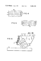
- FIG. 7 illustrates spot scarfing cuts made in accordance with the present invention when using several scarfing units mounted side-by-side in a "gang pass" arrangement.
- FIG. 8 illustrates "gang pass” scarfing cuts made by a scarfing machine in accordance with the invention that has been programmed to minimize oxygen and fuel gas consumption.
- FIG. 9 illustrates a sub-assembly useful for converting conventional scarfing apparatus to enable it to carry out the method of the present invention.
- FIGS. 1 and 2 illustrate a preferred embodiment of the invention.
- a scarfing unit U is comprised of a head 1, a shoe 2, an upper preheat block 3, and a lower preheat block 4.
- Shoe 2 rides on the surface of workpiece W, maintaining constant distances between the work surface and the scarfing unit U.
- Oxygen and fuel gas are supplied to the unit U by pipes 5 and 6, respectively, and thereafter to the various appropriate nozzles by conventional passages and flow control means (not completely shown) well known to those skilled in the art.
- Rows of ports 10 and 16 (see FIG. 2) in upper preheat block 3 discharge fuel gas and oxygen, respectively.
- a row of ports 11 in lower preheat block 4 discharge fuel gas.
- Conduit C P supplies oxygen to pilot oxygen nozzle 14 (see FIG. 2), which discharges a narrow stream of pilot oxygen gas to sustain the pilot puddle. Pilot oxygen nozzle 14 is located within scarfing oxygen slot nozzle 9. Conduit C s supplies oxygen to the parts of scarfing oxygen slot nozzle 9 located outside of pilot oxygen nozzle 14, and valves V 3 and V 4 control the flow of pilot oxygen and scarfing oxygen respectively. There may be more than one oxygen supply conduit conveying oxygen to the scarfing unit, and valves V 3 and V 4 may be located external to the scarfing unit.
- High intensity blowpipe 12 is mounted to discharge a high intensity stream of oxygen to spread out the pilot puddle sustained by nozzle 14 to the width desired for a scarfing cut.
- upper preheat block 3 be designed to produce a post-mixed preheating flame in accordance with Fuhrhop, U.S. Pat. No. 4,115,154, the entire disclosure of which is incorporated herein by reference.
- FIG. 3 illustrates typical spot scarfing cuts made on the surface of a workpiece by the apparatus described in FIGS. 1 and 2.
- scarfing cuts 23 and 25 would be made as follows.
- the end 20 of workpiece W is moved into register with scarfing unit U, (at the opposite end of the workpiece from that shown in the drawing) and relative motion between the workpiece and scarfing unit is stopped for the first and only time during the spot scarfing process.
- Fuel and oxygen gas are discharged from ports 10 and 16 and ignited, forming a preheat flame that impinges upon the small area 21 on the end 20 of the workpiece.
- the flame preheats portion 21 (P in FIG. 1) to at least its oxygen ignition temperature, preferably to its melting temperature.
- a narrow stream of pilot oxygen, directed at the heated portion 21, is then caused to be discharged from pilot nozzle 14 by partially opening valve V 3 .
- the pilot oxygen reacts exothermically with the heated portion 21 of the workpiece forming a molten puddle. Relative motion at normal scarfing speed is commenced between the scarfing unit U and the workpiece W. The scarfing unit passes over the workpiece in the general direction of arrow A. The pilot oxygen stream continuously produces a pilot puddle of molten metal along chosen path 22 on the surface of workpiece W. Flames formed by igniting gases discharged from nozzles 16, 10 and 11 can be used to help sustain the pilot puddle, although such flames are not necessary.
- Blowpipe 12 is caused to discharge a high intensity stream of oxygen which impinges upon pilot puddle 22.
- the pilot puddle is abruptly spread to width X, a preselected width equal to that of the desired scarfing cut.
- a stream of scarfing oxygen is simultaneously discharged from slot nozzle 9 onto the spread puddle by opening valve V 4 , and fully opening valve V 3 so that the oxygen flow from nozzle 14 is increased from the pilot oxygen intensity to scarfing intensity.
- area 23 is scarfed out. Preheat flames discharged from ports 11 help sustain the scarfing reaction.
- the scarfing oxygen of nozzle 9 is turned off by closing valve V 4 and partially closing valve V 3 so that the flow of oxygen from nozzle 14 is reduced to pilot oxygen stream intensity.
- Hot or molten metal remains at edge 23A of cut 23.
- Pilot oxygen from nozzle 14 impinges upon the hot or molten edge 23A and a pilot puddle is sustained along chosen path 24, in the same manner as for path 22.
- the path along which the pilot puddle is continuously produced does not have to be a straight line, but may follow any chosen path on the work surface.
- area 25, containing another defect is reached, the pilot puddle is spread suddenly by a high intensity stream of oxygen discharged from blowpipe 12, and area 25 is scarfed by again fully opening valves V 3 and V 4 .
- the pilot puddle 26 may be sustained by oxygen from nozzle 14 until the scarfing unit has passed over the workpiece.
- FIGS. 1 and 2 may be mounted to individually spot scarf defects located anywhere on the surface of a workpiece.
- An example of such mounting appears in FIG. 7 of U.S. Pat. No. 3,991,985.
- the scarfing method disclosed in U.S. Pat. No. 4,040,871, may be used.
- the intensity and width of the stream of pilot oxygen gas discharged from nozzle 14 should be just sufficient to sustain the pilot puddle. In this manner, very little metal will be removed from the path followed by the pilot puddle.
- the discharge opening of pilot oxygen nozzle 14 be a square measuring about 6 mm per side.
- the pilot oxygen stream intensity should be within the range of 40 to 70 SCMH/cm 2 of nozzle discharge area; preferably, it should be about 65 SCMH/cm 2 . If the workpiece temperature is above 760° C., the pilot oxygen stream intensity should be from 30 to 45 SCMH/cm 2 of nozzle discharge area; preferably, about 40 SCMH/cm 2 . At these intensities, a 6 mm square pilot nozzle arranged as shown in FIGS. 1 and 2 will produce a pilot puddle about 10 to 20 mm wide. The greater the distance between the workpiece and the mouth of the pilot oxygen nozzle, the greater the pilot oxygen stream intensity required. Different arrangements for the pilot oxygen nozzle are discussed later with regard to FIGS. 4, 5, 6 and 9.
- the high intensity stream of oxygen should preferably have an intensity of from 100 to 200 SCMH/cm 2 of nozzle discharge area, with about 115 SCMH/cm 2 being most preferred. It has been found in this instance, i.e., when initial workpiece temperature is less than 760° C., that an intensity of 115 SCMH/cm 2 discharged from a blowpipe of 20 mm diameter will spread a pilot puddle to a width of about 100 mm.
- a spot scarfing cut of this width may be sufficient; however, if a wider cut is desired, a 35 mm diameter blowpipe discharging at 115 SCMH/cm 2 will spread a pilot puddle to a width of about 200 mm or; a 45 mm diameter blowpipe will spread it to a width of about 300 mm.
- the intensity of the high intensity stream of oxygen should preferably be from 70 to 150 SCMH/cm 2 of nozzle discharge area when the workpiece temperature is above 760° C. with 95 SCMH/cm 2 being most preferred.
- said intensity of 95 SCMH/cm 2 discharged from a 20 mm diameter blowpipe will spread a pilot puddle to a width of about 100 mm, and if discharged from a 35 mm or 45 mm diameter blowpipe it will spread a pilot puddle to a width of about 200 mm or 300 mm, respectively.
- Scarfing oxygen stream intensity should preferably be from 40 to 100 SCMH/cm 2 of nozzle discharge area when scarfing workpieces having an initial temperature below 760° C., with about 85 SCMH/cm 2 being most preferred.
- scarfing oxygen stream intensity should preferably be from 45 to 70 SCMH/cm 2 , with 55 SCMH/cm 2 being most preferred.
- All the preheat ports 10 and 16 may be used to perform the preheating, or the scarfing unit may be provided with control means (not shown) so that only the preheat ports located near nozzle 14 are used for preheating.
- a pre-mixed flame that is, a flame formed by igniting oxygen and fuel gas that have been mixed within the scarfing unit may be used.
- Acceptable post-mixed preheating methods and apparatus are disclosed by Allmang and Lytle in U.S. Pat. Nos. 3,231,431 and 3,752,460.
- the method of Fuhrhop's U.S. Pat. No. 4,115,154 is preferred for producing a post-mixed flame.
- any method of heating a portion of the surface of the workpiece to its oxygen ignition temperature or melting temperature can be used, be it an electrical arc, or any other energy concentrating system.
- FIGS. 4 to 6 illustrate alternate preferred arrangements for supplying pilot oxygen gas to the surface of the workpiece.
- pilot oxygen nozzle 14A is located within upper preheat block 3.
- the apparatus illustrated in FIG. 5 has the pilot oxygen nozzle 14B located within lower preheat block 4.
- FIG. 6 is a side view illustrating still another arrangement for providing pilot oxygen.
- the pilot oxygen nozzle is a pipe 14C, located external to the scarfing unit above upper preheat block 3. Any nozzle arrangement capable of supplying pilot oxygen to a suitably located heated portion on the surface of the workpiece may be used.
- Two or more scarfing units constructed in accordance with the present invention may be mounted parallel to each other to make a "gang pass", i.e. simultaneous parallel passes by several scarfing units, over the workpiece.
- Nozzles so arranged may be mounted on a gantry as illustrated in FIG. 9 of U.S. Pat. No. 3,991,985. If fin-free cuts are desired, the gang-pass-mounted nozzles may be of the type disclosed in U.S. Pat. No. 4,013,486.
- FIG. 7 illustrates scarfing cuts made by apparatus comprising 3 units (31, 32 and 33) mounted side-by-side for a gang-pass over workpiece W.
- Scarfing units 31, 32 and 33 are constructed like those illustrated in FIGS. 1 and 2 and function in the same manner.
- FIG. 7 illustrates the position of the apparatus after the scarfing operation has been completed. The scarfing takes place as follows: edge 34 of workpiece W is positioned in register with the three scarfing units. Portions 35 and 36 of edge 34 are heated to at least oxygen ignition temperature by units 31 and 32 respectively, as described previously.
- unit 31 When area 41 is reached, unit 31 is turned on and suddenly spreads its pilot puddle with its high intensity blowpipe to the width of the desired scarfing cut and scarfs area 41. After area 41 has been scarfed, the scarfing oxygen stream of unit 31 is turned off, but the pilot oxygen stream is left on, sustaining a pilot puddle along path 42. After area 37 has been scarfed, the scarfing oxygen of unit 33 is turned off, leaving the pilot oxygen on to sustain the pilot puddle along path 43. When area 44 is reached, unit 33 suddenly spreads its pilot puddle to the desired width and area 44 is scarfed. Since there is no defect in the surface passed over by unit 32, that unit performs no scarfing during the entire pass.
- Relative motion between the workpiece and the scarfing apparatus may be along any chosen path, and may be provided by any desired means; either may move while the other is stationary, or both may move simultaneously.
- the means for producing said motion may be an integral part of the scarfing machinery, for example, as shown in FIGS. 7 and 9 of U.S. Pat. No. 3,991,985, mentioned previously.
- relative motion means external to the scarfing machine may be employed, for example, a steel mill's roll table which moves a workpiece in relation to a scarfing apparatus.
- FIG. 8 illustrates a workpiece scarfed by apparatus of the present invention that is programmed to conserve oxygen and fuel gas.
- the scarfing apparatus may be positioned at the edge of the first area to be scarfed, area 56, a distance "d" from edge 50 and halted there. While the apparatus is halted, units 31 and 33 preheat portions 51 and 52 and each unit's pilot oxygen is turned on. Simultaneously, a conventional scarfing start is made by unit 32 by preheating area 53 and turning on the scarfing oxygen. Relative motion between the gang pass apparatus and the workpiece is then immediately commenced, sustaining pilot puddles along paths 54 and 55 and making a scarfing cut over area 56.
- the scarfing oxygen on unit 32 is turned off, leaving pilot oxygen on to sustain a pilot puddle along path 58.
- unit 31 spreads its pilot puddle and scarfs the defect.
- unit 33 scarfs area 60 when that area is encountered.
- unit 31 is turned off completely, since that unit has no further defects to scarf.
- area 59 is encountered it is scarfed by unit 32.
- the programming method used to control the flows of gases from the various nozzles forms no part of this invention.
- Such programming could be accomplished manually by an operator who starts and stops gas flow from the appropriate nozzles at the appropriate times.
- the sequences for starting and sustaining the pilot puddle, and for spreading the puddle and scarfing a defect will be carried out automatically by sequencing apparatus.
- Defect detection apparatus could be used to detect defects and send signals to sequencing apparatus which could cause the defects to be automatically scarfed out of the workpiece.
- Programming apparatus into which the pattern of defects on a workpiece is pre-recorded before actual scarfing occurs may also be used.
- a first scarfing cut may be started by either the wire or laser method disclosed by said patents. After a cut has been made, a pilot puddle is sustained in the same way as that which was sustained along path 24 of FIG. 3, for example. Subsequent scarfing cuts are made by spreading the pilot puddle with a high intensity stream of oxygen and scarfing the desired area as described previously. This method has the advantage of not requiring a delay for preheating prior to the first scarfing cut, yet not requiring use of the wire feeder or laser to start subsequent cuts.
- FIG. 9 illustrates a sub-assembly useful for enabling conventional scarfing apparatus to carry out the method of the invention.
- U 1 represents any conventional scarfing unit having means (not shown) for preheating a portion of the surface of the workpiece to its oxygen ignition temperature and a scarfing nozzle 9.
- Sub-assembly S is connected to oxygen supply pipe or source 130. Oxygen is conducted from pipe 130 to pilot oxygen nozzle 14d and high intensity blowpipe 12d.
- the sub-assembly is shown mounted on scarfing unit U 1 , such that the oxygen streams discharged from nozzles 12d and 14d impinge upon the spot on the workpiece preheated by unit U 1 .
- unit U 1 preheats spot P on the surface of the workpiece to its oxygen ignition temperature.
- Valve V 2 has only a small flow opening that allows only a low-intensity stream of oxygen to flow from pilot oxygen nozzle 14d. A small pilot puddle is sustained along a chosen path. A high-intensity stream of oxygen is impinged upon the pilot puddle by opening valve V 1 spreading the puddle to a preselected width.
- Valve V 1 has a large flow opening that allows a high-intensity stream of oxygen to flow from nozzle 12d. The defective area is scarfed with a stream of scarfing oxygen discharged from nozzle 9.
- nozzles 12d and 14d may have separate supply pipes, and valves V 1 and V 2 or other means for controlling the flow of oxygen may be located external to the subassembly.
Abstract
Description
Claims (16)
Priority Applications (17)
| Application Number | Priority Date | Filing Date | Title |
|---|---|---|---|
| US06/091,162 US4243436A (en) | 1979-11-05 | 1979-11-05 | Instantaneous scarfing by means of a pilot puddle |
| US06/121,606 US4287005A (en) | 1979-11-05 | 1980-03-04 | Instantaneous scarfing by means of a pilot puddle |
| ES489930A ES8102873A1 (en) | 1979-03-28 | 1980-03-26 | Method and apparatus for instantaneous scarfing of a workpiece surface |
| DE3011648A DE3011648C2 (en) | 1979-03-28 | 1980-03-26 | Method and device for flame scarfing |
| BR8001845A BR8001845A (en) | 1979-03-28 | 1980-03-27 | PROCESS AND APPARATUS FOR POINT SCARFING, SUB-ASSEMBLY FOR USE IN COMBINATION WITH SCARFING EQUIPMENT AND PILOT SCARFING EQUIPMENT |
| AU56883/80A AU533950B2 (en) | 1979-03-28 | 1980-03-27 | Spot scarfing a metal workpiece |
| FR8006857A FR2452348B1 (en) | 1979-03-28 | 1980-03-27 | LOCAL SCREENING METHOD AND APPARATUS |
| MX181751A MX150221A (en) | 1979-03-28 | 1980-03-27 | IMPROVEMENTS IN PROCESS AND APPARATUS TO CHECK A METALLIC SURFACE BY POINTS |
| AR280466A AR222379A1 (en) | 1979-03-28 | 1980-03-27 | PROCEDURE FOR ESCAPING A METALLIC WORKPIECE |
| IT48274/80A IT1127016B (en) | 1979-03-28 | 1980-03-27 | INSTANTANEOUS DRYING PROCESS AND APPARATUS BY MEANS OF PILOT PELDING |
| GB8010343A GB2045143B (en) | 1979-03-28 | 1980-03-27 | Method and apparatus for instantaneous scarfing of a workpiece surface |
| NL8001818A NL8001818A (en) | 1979-03-28 | 1980-03-27 | METHOD AND APPARATUS FOR BURNING A METAL WORKPIECE |
| CA000348717A CA1142067A (en) | 1979-03-28 | 1980-03-28 | Instantaneous scarfing by means of a pilot puddle |
| TR21139A TR21139A (en) | 1979-03-28 | 1980-03-28 | Instant scraping with a pilot finder |
| SU802904348A SU1170961A3 (en) | 1979-11-05 | 1980-04-08 | Method of flame cleaning of metal blank surfaces and device for effecting same |
| ES494708A ES494708A0 (en) | 1979-03-28 | 1980-09-02 | A DEVICE TO ESCAPE BY POINTS OR ZONES |
| ES494709A ES494709A0 (en) | 1979-03-28 | 1980-09-02 | A SUBASSY, FOR USE IN COMBINATION WITH A THERMOCHEMICAL SPRAYING APPARATUS, CAPABLE OF PRODUCING A PILOT Puddle |
Applications Claiming Priority (1)
| Application Number | Priority Date | Filing Date | Title |
|---|---|---|---|
| US06/091,162 US4243436A (en) | 1979-11-05 | 1979-11-05 | Instantaneous scarfing by means of a pilot puddle |
Related Parent Applications (1)
| Application Number | Title | Priority Date | Filing Date |
|---|---|---|---|
| US2459779A Continuation | 1979-03-28 | 1979-03-28 |
Related Child Applications (1)
| Application Number | Title | Priority Date | Filing Date |
|---|---|---|---|
| US06/121,606 Continuation-In-Part US4287005A (en) | 1979-03-28 | 1980-03-04 | Instantaneous scarfing by means of a pilot puddle |
Publications (1)
| Publication Number | Publication Date |
|---|---|
| US4243436A true US4243436A (en) | 1981-01-06 |
Family
ID=22226381
Family Applications (1)
| Application Number | Title | Priority Date | Filing Date |
|---|---|---|---|
| US06/091,162 Expired - Lifetime US4243436A (en) | 1979-03-28 | 1979-11-05 | Instantaneous scarfing by means of a pilot puddle |
Country Status (1)
| Country | Link |
|---|---|
| US (1) | US4243436A (en) |
Cited By (4)
| Publication number | Priority date | Publication date | Assignee | Title |
|---|---|---|---|---|
| US4287005A (en) * | 1979-11-05 | 1981-09-01 | Union Carbide Corporation | Instantaneous scarfing by means of a pilot puddle |
| US4336923A (en) * | 1980-04-10 | 1982-06-29 | Sumitomo Metal Industries, Ltd. | Steel surface inspection apparatus |
| US4615377A (en) * | 1984-12-05 | 1986-10-07 | National Steel Corporation | Method of striping hot steel slabs |
| US20050129562A1 (en) * | 2003-10-17 | 2005-06-16 | Hoganas Ab | Method for the manufacturing of sintered metal parts |
Citations (10)
| Publication number | Priority date | Publication date | Assignee | Title |
|---|---|---|---|---|
| US3231431A (en) * | 1964-06-24 | 1966-01-25 | Union Carbide Corp | Post-mixed fuel gas preheat scarfing |
| US3455747A (en) * | 1966-09-14 | 1969-07-15 | Union Carbide Corp | Thermochemical scarfing method and apparatus |
| US3752460A (en) * | 1969-06-25 | 1973-08-14 | Union Carbide Corp | Oxygen trap scarfing apparatus |
| US3966503A (en) * | 1975-01-13 | 1976-06-29 | Union Carbide Corporation | Method for making instantaneous scarfing starts |
| US3991985A (en) * | 1975-01-13 | 1976-11-16 | Union Carbide Corporation | Apparatus for making an instantaneous scarfing start |
| US4013486A (en) * | 1975-08-26 | 1977-03-22 | Union Carbide Corporation | Spot scarfing nozzle for use in gang arrangement |
| US4038108A (en) * | 1976-05-10 | 1977-07-26 | Union Carbide Corporation | Method and apparatus for making an instantaneous thermochemical start |
| US4040871A (en) * | 1975-08-26 | 1977-08-09 | Union Carbide Corporation | Method for producing an individual fin-free spot scarfing cut |
| US4103877A (en) * | 1975-11-08 | 1978-08-01 | Messer Griesheim Gmbh. | Device for the flame treatment of a work-piece |
| US4115154A (en) * | 1977-09-26 | 1978-09-19 | Union Carbide Corporation | Method and apparatus for producing a post-mixed, stabilized scarfing pre-heating flame |
-
1979
- 1979-11-05 US US06/091,162 patent/US4243436A/en not_active Expired - Lifetime
Patent Citations (10)
| Publication number | Priority date | Publication date | Assignee | Title |
|---|---|---|---|---|
| US3231431A (en) * | 1964-06-24 | 1966-01-25 | Union Carbide Corp | Post-mixed fuel gas preheat scarfing |
| US3455747A (en) * | 1966-09-14 | 1969-07-15 | Union Carbide Corp | Thermochemical scarfing method and apparatus |
| US3752460A (en) * | 1969-06-25 | 1973-08-14 | Union Carbide Corp | Oxygen trap scarfing apparatus |
| US3966503A (en) * | 1975-01-13 | 1976-06-29 | Union Carbide Corporation | Method for making instantaneous scarfing starts |
| US3991985A (en) * | 1975-01-13 | 1976-11-16 | Union Carbide Corporation | Apparatus for making an instantaneous scarfing start |
| US4013486A (en) * | 1975-08-26 | 1977-03-22 | Union Carbide Corporation | Spot scarfing nozzle for use in gang arrangement |
| US4040871A (en) * | 1975-08-26 | 1977-08-09 | Union Carbide Corporation | Method for producing an individual fin-free spot scarfing cut |
| US4103877A (en) * | 1975-11-08 | 1978-08-01 | Messer Griesheim Gmbh. | Device for the flame treatment of a work-piece |
| US4038108A (en) * | 1976-05-10 | 1977-07-26 | Union Carbide Corporation | Method and apparatus for making an instantaneous thermochemical start |
| US4115154A (en) * | 1977-09-26 | 1978-09-19 | Union Carbide Corporation | Method and apparatus for producing a post-mixed, stabilized scarfing pre-heating flame |
Cited By (4)
| Publication number | Priority date | Publication date | Assignee | Title |
|---|---|---|---|---|
| US4287005A (en) * | 1979-11-05 | 1981-09-01 | Union Carbide Corporation | Instantaneous scarfing by means of a pilot puddle |
| US4336923A (en) * | 1980-04-10 | 1982-06-29 | Sumitomo Metal Industries, Ltd. | Steel surface inspection apparatus |
| US4615377A (en) * | 1984-12-05 | 1986-10-07 | National Steel Corporation | Method of striping hot steel slabs |
| US20050129562A1 (en) * | 2003-10-17 | 2005-06-16 | Hoganas Ab | Method for the manufacturing of sintered metal parts |
Similar Documents
| Publication | Publication Date | Title |
|---|---|---|
| US4084988A (en) | Method and apparatus for making instantaneous scarfing cuts | |
| US5304256A (en) | Scarfing method | |
| US2177276A (en) | Heating, welding, desurfacing, or cutting process and apparatus | |
| US4115154A (en) | Method and apparatus for producing a post-mixed, stabilized scarfing pre-heating flame | |
| US2288026A (en) | Method of and apparatus for initiating metal-removing operations | |
| US4243436A (en) | Instantaneous scarfing by means of a pilot puddle | |
| AU602730B2 (en) | Improved scarfing nozzle | |
| JPS621545Y2 (en) | ||
| CA1079181A (en) | Method and apparatus for producing a post-mixed, stabilized scarfing preheating flame | |
| US3966503A (en) | Method for making instantaneous scarfing starts | |
| US4287005A (en) | Instantaneous scarfing by means of a pilot puddle | |
| US3455747A (en) | Thermochemical scarfing method and apparatus | |
| US2208121A (en) | Apparatus for and method of controlling distortion | |
| US2510210A (en) | Method of thermochemically cutting metal bodies | |
| US3647570A (en) | Oxygen trap scarfing method and apparatus | |
| CA1091557A (en) | Method and apparatus for making an instantaneous thermochemical start | |
| US3991985A (en) | Apparatus for making an instantaneous scarfing start | |
| US2125179A (en) | Method of and apparatus for removing metal from the surfaces of metallic bodies | |
| US3608879A (en) | Device for trimming flash from metal which has been worked with a machining torch | |
| US3216867A (en) | Thermochemical scarfing process | |
| US2184560A (en) | Method of and apparatus for forming shaped edge on metal members | |
| CA1142067A (en) | Instantaneous scarfing by means of a pilot puddle | |
| KR840002339B1 (en) | Instantaneous scarfing by meaus of a pilot puddle | |
| USRE32511E (en) | Method and apparatus for making instantaneous scarfing cuts | |
| JP2896352B2 (en) | Gas processing torch ignition method and gas processing torch |
Legal Events
| Date | Code | Title | Description |
|---|---|---|---|
| AS | Assignment |
Owner name: L-TEC COMPANY, 666 THIRD AVENUE, NEW YORK, NY 100 Free format text: ASSIGNMENT OF ASSIGNORS INTEREST.;ASSIGNOR:UNION CARBIDE CORPORATION;REEL/FRAME:004436/0460 Effective date: 19850712 Owner name: L-TEC COMPANY, NEW YORK Free format text: ASSIGNMENT OF ASSIGNORS INTEREST;ASSIGNOR:UNION CARBIDE CORPORATION;REEL/FRAME:004436/0460 Effective date: 19850712 |
|
| AS | Assignment |
Owner name: SECURITY PACIFIC BUSINESS CREDIT INC., A DE CORP. Free format text: SECURITY INTEREST;ASSIGNOR:L-TEC COMPANY A NY LIMITED PARTNERSHIP;REEL/FRAME:004445/0860 Effective date: 19850716 |
|
| AS | Assignment |
Owner name: L-TEC COMPANY, EBENEEZER ROAD, POST OFFICE BOX F-6 Free format text: ASSIGNMENT OF ASSIGNORS INTEREST.;ASSIGNOR:UNION CARBIDE CORPORATION, A CORP OF NY.;REEL/FRAME:004610/0384 Effective date: 19860828 Owner name: L-TEC COMPANY, SOUTH CAROLINA Free format text: ASSIGNMENT OF ASSIGNORS INTEREST;ASSIGNOR:UNION CARBIDE CORPORATION, A CORP OF NY.;REEL/FRAME:004610/0384 Effective date: 19860828 |
|
| AS | Assignment |
Owner name: ESAB AB, A SWEDISH CORP., SWEDEN Free format text: ASSIGNMENT OF ASSIGNORS INTEREST.;ASSIGNOR:L-TEC COMPANY;REEL/FRAME:005491/0029 Effective date: 19901030 |