EP0806885B1 - Holding device for accessories mountable on a hearing aid - Google Patents
Holding device for accessories mountable on a hearing aid Download PDFInfo
- Publication number
- EP0806885B1 EP0806885B1 EP97103319A EP97103319A EP0806885B1 EP 0806885 B1 EP0806885 B1 EP 0806885B1 EP 97103319 A EP97103319 A EP 97103319A EP 97103319 A EP97103319 A EP 97103319A EP 0806885 B1 EP0806885 B1 EP 0806885B1
- Authority
- EP
- European Patent Office
- Prior art keywords
- hearing aid
- interface
- holding device
- holder
- accessories
- Prior art date
- Legal status (The legal status is an assumption and is not a legal conclusion. Google has not performed a legal analysis and makes no representation as to the accuracy of the status listed.)
- Expired - Lifetime
Links
Images

Classifications
-
- H—ELECTRICITY
- H04—ELECTRIC COMMUNICATION TECHNIQUE
- H04R—LOUDSPEAKERS, MICROPHONES, GRAMOPHONE PICK-UPS OR LIKE ACOUSTIC ELECTROMECHANICAL TRANSDUCERS; ELECTRIC HEARING AIDS; PUBLIC ADDRESS SYSTEMS
- H04R25/00—Electric hearing aids
- H04R25/55—Electric hearing aids using an external connection, either wireless or wired
- H04R25/556—External connectors, e.g. plugs or modules
Definitions
- the present invention relates to a hearing aid attachable holder for any hearing aid accessories, with one open on the front, one on one end Hearing aid slide-on housing and means for detachable Attach the holder to the hearing aid, being on the inside of the housing from attaching the respective component provided connection point from electrical conductor tracks for Lead front, which with attached bracket with to Hearing aid electronics leading connecting conductors on the hearing aid in Contact.
- Such mounts are under the technical name Audio shoe known.
- These brackets are usually included very specific components and can be Attach snap locks to the hearing aid. Depending on your needs each equipped with a specific accessory component Holder attached to the hearing aid. That it is a complex technology is not to be overlooked. in addition comes that when loosening the snap lock mechanical Defects can occur (when forcing the Bracket), which questions the reuse of the bracket can put.
- the object of the present invention is an audio shoe (Holder for components) so that on the one hand an exchange of components on the bracket is possible and also preferably at the same time unnecessary mechanical defects is met, i.e. great compatibility with components and hearing aids are also guaranteed with different battery sizes is.
- the bracket thus serves as a connecting part between the Hearing aid and the various accessories.
- the holder surrounding the hearing aid is individual different types of hearing aids can be structurally adjusted.
- Interface developed, whose mechanical dimensions for all brackets are the same.
- the attachment of the accessory components e.g. using two screws.
- connection at the universal interface is mechanical and electrically stable and not for the user without tools accessible.
- the bracket is preferably spring-actuated Locking latch held on to the hearing aid.
- the bracket can only by spring-releasing finger pressure on the bolt from Hearing aid are removed. This construction prevents that unintentional falling of the holder from the hearing aid.
- mechanical wear as is the case with conventional ones Plastic snapping is the case with this locking system avoided.
- Fig. 1 of the drawing shows the connection purely schematically an accessory component with the universal interface the holder (audio shoe) and via this with the electronics contacts on the hearing aid.
- Fig. 2 shows a holder 1 for placement on a hearing aid with interface 2, the actuation button for locking, as well as two different accessory components 4 'or 4 "(e.g. Radio signal receiver).
- 4 'or 4 e.g. Radio signal receiver
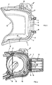
- FIG. 3 shows a holder 1 consisting of a housing 1 ' (Plastic shoe) with opening 5 on the front, one formed as interface 6 with associated electrical contact springs 7, 8 (one pair each), which are provided with contacts of the printed circuit boards the accessory component to be attached (not shown) in to achieve a mechanically and electrically stable connection.
- the contact springs 7, 8 lead via conductors 7 ', 8' to the housing opening, after having been put on a hearing aid end Mating contacts of the hearing aid electronics in mechanical and electrically stable connection.
- a latch 9 is provided, which on the inner wall of the housing led from one side of the housing to overlying leads and there under the influence of a Compression spring 10 is held in the closed position (at mounted bracket), the locking lug 9 'in a corresponding recess on the hearing aid clicks in and out of this Position can only be released if the button 9 "on Pressure is exerted against the action of the spring 10.
- the locking lug 9 'could also be directly in the Nose area arranged spring-loaded actuation mechanism operated (not shown).
- FIG. 4 finally shows a holder 11 according to FIG. 3 whose connection point 12 (interface) is more appropriate Accessory component 13 in the end of a hearing aid 14 attached position.
- the electrical ones are clearly visible Conductors 7, 7 'and 8, 8' in contact with circuit boards 15, 16 of Accessory component 13 or the mating contacts 17, 18 of the hearing aid.
- the circuit boards 15, 16 of the component 13 are thereby also by means of compression springs 19 against the conductor 7 or 8 pressed.
Landscapes
- Engineering & Computer Science (AREA)
- Computer Networks & Wireless Communication (AREA)
- Health & Medical Sciences (AREA)
- General Health & Medical Sciences (AREA)
- Neurosurgery (AREA)
- Otolaryngology (AREA)
- Physics & Mathematics (AREA)
- Acoustics & Sound (AREA)
- Signal Processing (AREA)
- Adornments (AREA)
- Telephone Set Structure (AREA)
- Purses, Travelling Bags, Baskets, Or Suitcases (AREA)
- Measurement Of The Respiration, Hearing Ability, Form, And Blood Characteristics Of Living Organisms (AREA)
Abstract
Description
Die vorliegende Erfindung betrifft eine auf ein Hörgerät aufsetzbare Halterung für beliebige Hörgerät-Zubehörkomponenten, mit einem auf der Vorderseite offenen, auf ein Ende eines Hörgerätes aufschiebbaren Gehäuse und Mitteln zum lösbaren Befestigen der Halterung am Hörgerät, wobei auf der Gehäuseinnenseite von der zur Anbringung der jeweiligen Komponente vorgesehenen Verbindungsstelle aus elektrische Leiterbahnen zur Vorderseite führen, welche bei aufgesetzter Halterung mit zur Hörgeräteelektronik führenden Verbindungsleitern am Hörgerät in Kontakt gelangen.The present invention relates to a hearing aid attachable holder for any hearing aid accessories, with one open on the front, one on one end Hearing aid slide-on housing and means for detachable Attach the holder to the hearing aid, being on the inside of the housing from attaching the respective component provided connection point from electrical conductor tracks for Lead front, which with attached bracket with to Hearing aid electronics leading connecting conductors on the hearing aid in Contact.
Derartige Halterungen sind unter der Fachbezeichnung Audio-Schuh bekannt. Diese Halterungen sind in der Regel mit ganz bestimmten Komponenten ausgerüstet und lassen sich mittels Schnappverschlüssen am Hörgerät anbringen. Je nach Bedarf wird jeweils ein mit einer bestimmten Zubehörkomponente ausgerüsteter Halter am Hörgerät angebracht. Dass es sich dabei um eine aufwendige Technologie handelt, ist nicht zu übersehen. Hinzu kommt, dass beim Lösen des Schnappverschlusses mechanische Defekte auftreten können (beim forcierten Abziehen der Halterung), welche die Weiterverwendung der Halterung in Frage stellen können.Such mounts are under the technical name Audio shoe known. These brackets are usually included very specific components and can be Attach snap locks to the hearing aid. Depending on your needs each equipped with a specific accessory component Holder attached to the hearing aid. That it is a complex technology is not to be overlooked. in addition comes that when loosening the snap lock mechanical Defects can occur (when forcing the Bracket), which questions the reuse of the bracket can put.
So sind Halterungen aus EP-0 087 668, DE-G-93 06 204.4 und EP-0 334 837 bekannt, bei denen Steckerbuchsen zum Anschliessen von Verbindungsleitungen vorgesehen sind. Diese Steckerbuchsen sind mit elektrischen Leiterbahnen versehen, die zu Kontaktstellen mit dem Hörgerät führen. Aufgabe der vorliegenden Erfindung ist es, einen Audio-Schuh (Halterung für Komponenten) so zu gestalten, dass einerseits ein Austausch von Komponenten an der Halterung möglich ist und zudem vorzugsweise gleichzeitig unnötigen mechanischen Defekten begegnet wird, d.h. eine grosse Kompatibilität mit Komponenten und Hörgeräten auch mit verschiedenen Batteriegrössen gewährleistet ist.So are mounts from EP-0 087 668, DE-G-93 06 204.4 and EP-0 334 837 known, in which plug sockets for connection of connecting lines are provided. These sockets are provided with electrical conductor tracks that lead to contact points with the hearing aid. The object of the present invention is an audio shoe (Holder for components) so that on the one hand an exchange of components on the bracket is possible and also preferably at the same time unnecessary mechanical defects is met, i.e. great compatibility with components and hearing aids are also guaranteed with different battery sizes is.
Diese Aufgabe wird bei einer auf ein Hörgerät aufsetzbaren Halterung der eingangs definierten Art erfindungsgemäss durch die Merkmale gemäss dem kennzeichnenden Teil von Anspruch 1 gelöst.This task becomes possible with a hearing aid Holder of the type defined in the introduction by the features according to the characterizing part of claim 1 solved.
Die Halterung dient somit als Verbindungsteil zwischen dem Hörgerät und den verschiedenen Zubehörkomponenten.The bracket thus serves as a connecting part between the Hearing aid and the various accessories.
Dank der als universelle Schnittstelle des Systems ausgebildeten Verbindungsstelle an der Halterung kann der Akustiker das von ihm bzw. dem Hörgerätebenutzer gewünschte Zubehör ohne grosse Umbauarbeiten an der Halterung anschliessen. Die Montage wird dadurch erleichtert, dass sehr wenig und erst noch unverlierbare Teile vorgesehen sind.Thanks to the training as the universal interface of the system The acoustician can do this at the connection point on the bracket accessories desired by him or the hearing aid user without Connect major modifications to the bracket. The assembly is facilitated by the fact that very little and yet captive parts are provided.
Die das Hörgerät umschliessende Halterung ist individuell den verschiedenen Hörgerätetypen kontruktiv anpassbar. Für den Anschluss der Zubehörkomponenten wurde eine definierte Schnittstelle entwickelt, deren mechanische Abmessungen für alle Halterungen gleich sind. Der Anbau der Zubehörkomponenten erfolgt z.B. mittels zweier Schrauben. The holder surrounding the hearing aid is individual different types of hearing aids can be structurally adjusted. For the Connection of the accessory components has been defined Interface developed, whose mechanical dimensions for all brackets are the same. The attachment of the accessory components e.g. using two screws.
Die Verbindung an der universellen Schnittstelle ist mechanisch und elektrisch stabil und für den Benutzer ohne Werkzeuge nicht zugänglich.The connection at the universal interface is mechanical and electrically stable and not for the user without tools accessible.
Besondere Ausführungsformen der erfindungsgemässen Halterung sind in den abhängigen Ansprüchen definiert.Special embodiments of the holder according to the invention are defined in the dependent claims.
Die Halterung wird vorzugsweise mittels eines federbetätigten Verschlussriegels am Hörgerät festgehalten. Die Halterung kann nur mittels federentlastendem Fingerdruck auf den Riegel vom Hörgerät entfernt werden. Diese Konstruktion verhindert das unbeabsichtigte Abfallen der Halterung vom Hörgerät. Zudem wird eine mechanische Abnutzung, wie es bei herkömmlichen Kunststoffschnappern der Fall ist, mit diesem Riegelsystem vermieden.The bracket is preferably spring-actuated Locking latch held on to the hearing aid. The bracket can only by spring-releasing finger pressure on the bolt from Hearing aid are removed. This construction prevents that unintentional falling of the holder from the hearing aid. In addition, mechanical wear, as is the case with conventional ones Plastic snapping is the case with this locking system avoided.
Die Erfindung wird nachstehend anhand von in der Zeichnung dargestellten Ausführungsbeispielen noch etwas näher erläutert.The invention is illustrated below in the drawing illustrated embodiments explained in more detail.
Es zeigen:
- Fig. 1
- die schematische Darstellung der Zusammenwirkung von Hörgerät und Zubehörkomponente über die Schnittstelle der Halterung;
- Fig. 2
- eine schaubildliche Darstellung einer erfindungsgemässen Halterung mit zwei verschiedenen Zubehör-Komponenten;
- Fig. 3
- eine Seitenansicht einer Halterung (Audio-Schuh) nach der Erfindung; und
- Fig. 4
- eine Halterung nach Fig. 3 mit angebrachter Komponente, aufgesetzt auf das mit Batteriefach ausgerüstete Ende eines Hörgerätes.
- Fig. 1
- the schematic representation of the interaction of hearing aid and accessory component via the interface of the holder;
- Fig. 2
- a diagrammatic representation of a holder according to the invention with two different accessory components;
- Fig. 3
- a side view of a holder (audio shoe) according to the invention; and
- Fig. 4
- 3 with attached component, placed on the end of a hearing aid equipped with a battery compartment.
Fig. 1 der Zeichnung zeigt rein schematisch die Verbindung einer Zubehörkomponente mit der universellen Schnittstelle an der Halterung (Audio-Schuh) und über diese mit den Elektronik-Kontakten am Hörgerät.Fig. 1 of the drawing shows the connection purely schematically an accessory component with the universal interface the holder (audio shoe) and via this with the electronics contacts on the hearing aid.
Fig. 2 zeigt eine Halterung 1 zum Aufsetzen auf ein Hörgerät
mit Schnittstelle 2, dem Betätigungsknopf für die Verriegelung,
sowie zwei verschiedenen Zubehör-Komponenten 4' bzw. 4" (z.B.
Funksignal-Empfänger).Fig. 2 shows a holder 1 for placement on a hearing aid
with
Fig. 3 zeigt eine Halterung 1, bestehend aus einem Gehäuse 1'
(Kunststoff-Schuh) mit Oeffnung 5 auf der Vorderseite, einer
als Schnittstelle ausgebildeten Verbindungsstelle 6 mit
zugehörigen elektrischen Kontaktfedern 7, 8 (je ein Paar),
welche dazu vorgesehen sind, mit Kontakten der Leiterplatten
der aufzusetzenden Zubehörkomponente (nicht dargestellt) in
eine mechanisch und elektrisch stabile Verbindung zu gelangen.
Die Kontaktfedern 7, 8 führen über Leiter 7', 8' zur Gehäuseöffnung,
um nach dem Aufsetzen auf ein Hörgerätende mit
Gegenkontakten der Hörgerätelektronik in mechanisch und
elektrisch stabile Verbindung zu treten.3 shows a holder 1 consisting of a housing 1 '
(Plastic shoe) with opening 5 on the front, one
formed as
Ferner ist ein Riegel 9 vorgesehen, welcher an der Gehäuseinnenwand
geführt von der einen Gehäuseschmalseite zur
gebenüberliegenden führt und dort unter dem Einfluss einer
Druckfeder 10 in Schliessstellung gehalten wird (bei
aufgesetzter Halterung), wobei die Riegelnase 9' in eine
entsprechende Vertiefung am Hörgerät einrastet und aus dieser
Stellung nur gelöst werden kann, wenn auf den Knopf 9" ein
Druck gegen die Wirkung der Feder 10 ausgeübt wird.Furthermore, a
Die Verriegelungsnase 9' könnte auch durch einen direkt im Nasenbereich angeordneten federbelasteten Betätigungsmechanismus betrieben werden (nicht dargestellt).The locking lug 9 'could also be directly in the Nose area arranged spring-loaded actuation mechanism operated (not shown).
Dank der beschriebenen Verriegelung lässt sich eine auf ein
Hörgerät aufgesetzte Halterung nur lösen, wenn der Knopf 9"
betätigt wird. Damit wird einerseits unbeabsichtigten
Beschädigungen vorgebeugt und andererseits werden wesentlich
stabilere elektrische Verbindungen erzielt.Thanks to the lock described, one can be opened
Only release the hearing aid holder when the
Fig. 4 schliesslich zeigt eine Halterung 11 nach Fig. 3 mit an
deren Verbindungsstelle 12 (Schnittstelle) angebrachter
Zubehör-Komponente 13 in deren auf ein Hörgerätende 14
aufgesetzter Stellung. Gut sichtbar sind dabei die elektrischen
Leiter 7, 7' bzw. 8, 8' in Kontakt mit Leiterplatten 15, 16 der
Zubehörkomponente 13 bzw. den Gegenkontakten 17, 18 des Hörgerätes.
Die Leiterplatten 15, 16 der Komponente 13 werden
dabei mittels Druckfedern 19 zusätzlich gegen die Leiter 7 bzw.
8 gedrückt.FIG. 4 finally shows a
Durch das erfindungsgemässe Konzept der Halterung kann die Lagerhaltung beim Akustiker auf ein Minimum beschränkt werden. Die preisgünstigen Halterungen und die aufwendigeren Zubehörkomponenten können separat bewirtschaftet und erst bei Bedarf kompletiert werden.Due to the inventive concept of the holder, the Storage by the acoustician can be kept to a minimum. The inexpensive brackets and the more complex ones Accessory components can be managed separately and only at Needs to be completed.
Claims (4)
- Holding device (1, 11) which can be mounted on a hearing aid, having a first interface (5), which can be connected to the hearing aid, and a second interface (2, 6), and having electrical conductor tracks (7, 7', 8, 8') leading from the first interface (5) to the second interface (2, 6), characterized in that any desired accessories (4', 4'', 13) can be joined to the second interface (2, 6), and in that the second interface (2, 6) comprises at least two opposite electrical contact springs (8, 8') which are designed in such a way as to ensure a mechanically and also electrically stable connection to the printed circuit boards (15, 16) belonging to the accessories (4', 4", 13).
- Holding device (1, 11) according to Claim 1, characterized in that the opposite contact springs (8, 8') are spaced apart from each other in such a way that two printed circuit boards (15, 16) which can be received in the second interface (2, 6) are contactable, at least one compression spring (19) being provided and acting in the direction of both contact springs (8, 8').
- Holding device (1, 11) according to Claim 1 or 2, characterized in that a locking mechanism (9, 9', 10) for releasably attaching the holding device (1, 11) to the hearing aid is formed by a spring-loaded mechanical link (9, 10), which locking mechanism (9, 9', 10) can be released via an integrated actuating mechanism (9").
- Holding device according to Claim 3, characterized in that the spring-loaded locking mechanism (9, 9', 10) has a locking nose (9') at its end.
Applications Claiming Priority (3)
| Application Number | Priority Date | Filing Date | Title |
|---|---|---|---|
| CH1143/96 | 1996-05-06 | ||
| CH114396 | 1996-05-06 | ||
| CH114396 | 1996-05-06 |
Publications (2)
| Publication Number | Publication Date |
|---|---|
| EP0806885A1 EP0806885A1 (en) | 1997-11-12 |
| EP0806885B1 true EP0806885B1 (en) | 2001-10-04 |
Family
ID=4203502
Family Applications (1)
| Application Number | Title | Priority Date | Filing Date |
|---|---|---|---|
| EP97103319A Expired - Lifetime EP0806885B1 (en) | 1996-05-06 | 1997-02-28 | Holding device for accessories mountable on a hearing aid |
Country Status (4)
| Country | Link |
|---|---|
| EP (1) | EP0806885B1 (en) |
| AT (1) | ATE206578T1 (en) |
| DE (1) | DE59704749D1 (en) |
| DK (1) | DK0806885T3 (en) |
Cited By (3)
| Publication number | Priority date | Publication date | Assignee | Title |
|---|---|---|---|---|
| USD484983S1 (en) | 2002-09-16 | 2004-01-06 | Widex A/S | Combined module and adapter for attachment to a hearing aid |
| DE102005061795A1 (en) * | 2005-12-23 | 2007-07-05 | Siemens Audiologische Technik Gmbh | hearing aid module |
| US12149894B2 (en) | 2021-09-27 | 2024-11-19 | Sonova Ag | Hearing device plug connector and hearing device |
Families Citing this family (8)
| Publication number | Priority date | Publication date | Assignee | Title |
|---|---|---|---|---|
| DE10048342C1 (en) * | 2000-09-29 | 2002-03-07 | Siemens Audiologische Technik | Hearing aid remote-control provides storage facility for hearing aid and/or hearing aid accessories |
| CN1751538B (en) * | 2003-03-06 | 2011-11-09 | 唯听助听器公司 | Adapter mounts, accessories and combinations thereof for attachment to hearing aids |
| US7450732B2 (en) | 2003-06-13 | 2008-11-11 | Oticon A/S | Electrical and mechanical connection between head worn communication device and accessory thereto |
| DE102005041356B4 (en) * | 2005-08-31 | 2009-07-23 | Siemens Audiologische Technik Gmbh | Audio shoe contact for a hearing aid |
| DE102006036069B4 (en) * | 2006-07-18 | 2008-09-04 | Cerbomed Gmbh | Audiological transmission system |
| DE102007033714A1 (en) * | 2007-07-19 | 2009-01-22 | Siemens Medical Instruments Pte. Ltd. | Hearing device with a fastening device for connecting an audio shoe and a corresponding audio shoe |
| WO2010027328A1 (en) * | 2008-09-08 | 2010-03-11 | Siemens Medical Instruments Pte Ltd | Insect repellant hearing aid |
| AU2018203536B2 (en) * | 2017-05-23 | 2022-06-30 | Cochlear Limited | Hearing Aid Device Unit Along a Single Curved Axis |
Family Cites Families (4)
| Publication number | Priority date | Publication date | Assignee | Title |
|---|---|---|---|---|
| CH641619A5 (en) * | 1979-08-30 | 1984-02-29 | Phonak Ag | Hearing-aid with receiver part |
| DE3207256A1 (en) * | 1982-03-01 | 1983-09-15 | Siemens AG, 1000 Berlin und 8000 München | HOERHILFEGERAET |
| AT388837B (en) * | 1988-03-22 | 1989-09-11 | Viennatone Gmbh | HEARING DEVICE WITH AUDIO INPUT CONNECTION |
| DE9306204U1 (en) * | 1992-09-10 | 1993-06-24 | Siemens AG, 8000 München | Adapter and hearing aid device that is technically and functionally related to it |
-
1997
- 1997-02-28 DE DE59704749T patent/DE59704749D1/en not_active Expired - Fee Related
- 1997-02-28 DK DK97103319T patent/DK0806885T3/en active
- 1997-02-28 EP EP97103319A patent/EP0806885B1/en not_active Expired - Lifetime
- 1997-02-28 AT AT97103319T patent/ATE206578T1/en not_active IP Right Cessation
Cited By (4)
| Publication number | Priority date | Publication date | Assignee | Title |
|---|---|---|---|---|
| USD484983S1 (en) | 2002-09-16 | 2004-01-06 | Widex A/S | Combined module and adapter for attachment to a hearing aid |
| DE102005061795A1 (en) * | 2005-12-23 | 2007-07-05 | Siemens Audiologische Technik Gmbh | hearing aid module |
| DE102005061795B4 (en) * | 2005-12-23 | 2008-01-03 | Siemens Audiologische Technik Gmbh | hearing aid module |
| US12149894B2 (en) | 2021-09-27 | 2024-11-19 | Sonova Ag | Hearing device plug connector and hearing device |
Also Published As
| Publication number | Publication date |
|---|---|
| EP0806885A1 (en) | 1997-11-12 |
| DE59704749D1 (en) | 2001-11-08 |
| DK0806885T3 (en) | 2001-11-19 |
| ATE206578T1 (en) | 2001-10-15 |
Similar Documents
| Publication | Publication Date | Title |
|---|---|---|
| EP0806885B1 (en) | Holding device for accessories mountable on a hearing aid | |
| DE19755018C1 (en) | Conductor card fastening arrangement | |
| EP0491072B1 (en) | Hearing aid | |
| DE4310855A1 (en) | Device for monitoring at least one connection of a medical hose line system | |
| DE102007004545A1 (en) | Electrical connection terminal | |
| EP0781460B1 (en) | Electronic device, in particular an automatic-control device | |
| DE102014000294A1 (en) | Side door lock for a motor vehicle | |
| DE202014104939U1 (en) | Terminal for the electrical connection of a conductor | |
| DE8216204U1 (en) | Relay socket | |
| DE102009050595B4 (en) | Electrical safety socket | |
| DE102024103650B4 (en) | Medical device | |
| DE102015106578B4 (en) | Modular electronics housing | |
| DE102004061526A1 (en) | Connection structure between a busbar base and a printed circuit board | |
| DE4121311C1 (en) | ||
| DE602004012811T2 (en) | Mounting arrangement of a plug and mobile device | |
| EP3738175A1 (en) | Plug connector assembly | |
| EP0660458B1 (en) | Connection device for telecommunications / data lines | |
| DE202007016121U1 (en) | Handle for a motor vehicle door with trim strip | |
| DE202006017315U1 (en) | Wireless RF transmitter handset e.g. for door, has functional part and covering part joined to each other by locking, releasable pluggable connection | |
| EP0634086B1 (en) | Pluggable screw-type terminal arrangement for compact programmable controllers | |
| DE9306204U1 (en) | Adapter and hearing aid device that is technically and functionally related to it | |
| DE19521124C1 (en) | Termination device for loudspeaker box | |
| DE69320198T2 (en) | Electrical connector with jumpers | |
| DE19750307A1 (en) | Electronic apparatus, in particular telephone apparatus and process for its manufacture | |
| DE102017104819A1 (en) | Component, assembly aid and method for soldering the component |
Legal Events
| Date | Code | Title | Description |
|---|---|---|---|
| PUAI | Public reference made under article 153(3) epc to a published international application that has entered the european phase |
Free format text: ORIGINAL CODE: 0009012 |
|
| AK | Designated contracting states |
Kind code of ref document: A1 Designated state(s): AT DE DK GB IT SE AT DE |
|
| 17P | Request for examination filed |
Effective date: 19980508 |
|
| 17Q | First examination report despatched |
Effective date: 19980617 |
|
| RBV | Designated contracting states (corrected) |
Designated state(s): AT DE DK GB IT SE |
|
| RBV | Designated contracting states (corrected) |
Designated state(s): AT CH DE DK GB IT LI SE |
|
| GRAG | Despatch of communication of intention to grant |
Free format text: ORIGINAL CODE: EPIDOS AGRA |
|
| APAB | Appeal dossier modified |
Free format text: ORIGINAL CODE: EPIDOS NOAPE |
|
| APBJ | Interlocutory revision of appeal recorded |
Free format text: ORIGINAL CODE: EPIDOS IRAPE |
|
| GRAG | Despatch of communication of intention to grant |
Free format text: ORIGINAL CODE: EPIDOS AGRA |
|
| GRAH | Despatch of communication of intention to grant a patent |
Free format text: ORIGINAL CODE: EPIDOS IGRA |
|
| GRAH | Despatch of communication of intention to grant a patent |
Free format text: ORIGINAL CODE: EPIDOS IGRA |
|
| GRAA | (expected) grant |
Free format text: ORIGINAL CODE: 0009210 |
|
| AK | Designated contracting states |
Kind code of ref document: B1 Designated state(s): AT CH DE DK GB IT LI SE |
|
| PG25 | Lapsed in a contracting state [announced via postgrant information from national office to epo] |
Ref country code: IT Free format text: LAPSE BECAUSE OF FAILURE TO SUBMIT A TRANSLATION OF THE DESCRIPTION OR TO PAY THE FEE WITHIN THE PRESCRIBED TIME-LIMIT;WARNING: LAPSES OF ITALIAN PATENTS WITH EFFECTIVE DATE BEFORE 2007 MAY HAVE OCCURRED AT ANY TIME BEFORE 2007. THE CORRECT EFFECTIVE DATE MAY BE DIFFERENT FROM THE ONE RECORDED. Effective date: 20011004 |
|
| REF | Corresponds to: |
Ref document number: 206578 Country of ref document: AT Date of ref document: 20011015 Kind code of ref document: T |
|
| REG | Reference to a national code |
Ref country code: CH Ref legal event code: NV Representative=s name: TROESCH SCHEIDEGGER WERNER AG Ref country code: CH Ref legal event code: EP |
|
| GBT | Gb: translation of ep patent filed (gb section 77(6)(a)/1977) |
Effective date: 20011004 |
|
| REF | Corresponds to: |
Ref document number: 59704749 Country of ref document: DE Date of ref document: 20011108 |
|
| REG | Reference to a national code |
Ref country code: DK Ref legal event code: T3 |
|
| REG | Reference to a national code |
Ref country code: GB Ref legal event code: IF02 |
|
| PG25 | Lapsed in a contracting state [announced via postgrant information from national office to epo] |
Ref country code: SE Free format text: LAPSE BECAUSE OF FAILURE TO SUBMIT A TRANSLATION OF THE DESCRIPTION OR TO PAY THE FEE WITHIN THE PRESCRIBED TIME-LIMIT Effective date: 20020104 |
|
| PG25 | Lapsed in a contracting state [announced via postgrant information from national office to epo] |
Ref country code: AT Free format text: LAPSE BECAUSE OF NON-PAYMENT OF DUE FEES Effective date: 20020228 |
|
| PLBE | No opposition filed within time limit |
Free format text: ORIGINAL CODE: 0009261 |
|
| STAA | Information on the status of an ep patent application or granted ep patent |
Free format text: STATUS: NO OPPOSITION FILED WITHIN TIME LIMIT |
|
| 26N | No opposition filed | ||
| PGFP | Annual fee paid to national office [announced via postgrant information from national office to epo] |
Ref country code: DK Payment date: 20070215 Year of fee payment: 11 |
|
| PGFP | Annual fee paid to national office [announced via postgrant information from national office to epo] |
Ref country code: DE Payment date: 20070222 Year of fee payment: 11 |
|
| PGFP | Annual fee paid to national office [announced via postgrant information from national office to epo] |
Ref country code: GB Payment date: 20070228 Year of fee payment: 11 |
|
| PGFP | Annual fee paid to national office [announced via postgrant information from national office to epo] |
Ref country code: CH Payment date: 20070425 Year of fee payment: 11 |
|
| REG | Reference to a national code |
Ref country code: DK Ref legal event code: EBP |
|
| REG | Reference to a national code |
Ref country code: CH Ref legal event code: PL |
|
| GBPC | Gb: european patent ceased through non-payment of renewal fee |
Effective date: 20080228 |
|
| PG25 | Lapsed in a contracting state [announced via postgrant information from national office to epo] |
Ref country code: LI Free format text: LAPSE BECAUSE OF NON-PAYMENT OF DUE FEES Effective date: 20080229 Ref country code: CH Free format text: LAPSE BECAUSE OF NON-PAYMENT OF DUE FEES Effective date: 20080229 |
|
| PG25 | Lapsed in a contracting state [announced via postgrant information from national office to epo] |
Ref country code: DK Free format text: LAPSE BECAUSE OF NON-PAYMENT OF DUE FEES Effective date: 20080229 Ref country code: DE Free format text: LAPSE BECAUSE OF NON-PAYMENT OF DUE FEES Effective date: 20080902 |
|
| PG25 | Lapsed in a contracting state [announced via postgrant information from national office to epo] |
Ref country code: GB Free format text: LAPSE BECAUSE OF NON-PAYMENT OF DUE FEES Effective date: 20080228 |