EP0806850B1 - Méthode pour la transmission de signaux de radiodiffusion en modulation par multiplexage par répartition orthogonale de la fréquence codée à travers un système de satellite - Google Patents
Méthode pour la transmission de signaux de radiodiffusion en modulation par multiplexage par répartition orthogonale de la fréquence codée à travers un système de satellite Download PDFInfo
- Publication number
- EP0806850B1 EP0806850B1 EP97103914A EP97103914A EP0806850B1 EP 0806850 B1 EP0806850 B1 EP 0806850B1 EP 97103914 A EP97103914 A EP 97103914A EP 97103914 A EP97103914 A EP 97103914A EP 0806850 B1 EP0806850 B1 EP 0806850B1
- Authority
- EP
- European Patent Office
- Prior art keywords
- satellite
- signal
- delay
- reference point
- cofdm
- Prior art date
- Legal status (The legal status is an assumption and is not a legal conclusion. Google has not performed a legal analysis and makes no representation as to the accuracy of the status listed.)
- Expired - Lifetime
Links
Images


Classifications
-
- H—ELECTRICITY
- H04—ELECTRIC COMMUNICATION TECHNIQUE
- H04H—BROADCAST COMMUNICATION
- H04H20/00—Arrangements for broadcast or for distribution combined with broadcast
- H04H20/44—Arrangements characterised by circuits or components specially adapted for broadcast
- H04H20/46—Arrangements characterised by circuits or components specially adapted for broadcast specially adapted for broadcast systems covered by groups H04H20/53-H04H20/95
- H04H20/51—Arrangements characterised by circuits or components specially adapted for broadcast specially adapted for broadcast systems covered by groups H04H20/53-H04H20/95 specially adapted for satellite broadcast systems
-
- H—ELECTRICITY
- H04—ELECTRIC COMMUNICATION TECHNIQUE
- H04B—TRANSMISSION
- H04B7/00—Radio transmission systems, i.e. using radiation field
- H04B7/14—Relay systems
- H04B7/15—Active relay systems
- H04B7/185—Space-based or airborne stations; Stations for satellite systems
- H04B7/18523—Satellite systems for providing broadcast service to terrestrial stations, i.e. broadcast satellite service
-
- H—ELECTRICITY
- H04—ELECTRIC COMMUNICATION TECHNIQUE
- H04H—BROADCAST COMMUNICATION
- H04H20/00—Arrangements for broadcast or for distribution combined with broadcast
- H04H20/65—Arrangements characterised by transmission systems for broadcast
- H04H20/71—Wireless systems
- H04H20/74—Wireless systems of satellite networks
-
- H—ELECTRICITY
- H04—ELECTRIC COMMUNICATION TECHNIQUE
- H04L—TRANSMISSION OF DIGITAL INFORMATION, e.g. TELEGRAPHIC COMMUNICATION
- H04L27/00—Modulated-carrier systems
- H04L27/26—Systems using multi-frequency codes
- H04L27/2601—Multicarrier modulation systems
-
- H—ELECTRICITY
- H04—ELECTRIC COMMUNICATION TECHNIQUE
- H04H—BROADCAST COMMUNICATION
- H04H2201/00—Aspects of broadcast communication
- H04H2201/10—Aspects of broadcast communication characterised by the type of broadcast system
- H04H2201/20—Aspects of broadcast communication characterised by the type of broadcast system digital audio broadcasting [DAB]
Definitions
- the invention relates to a method for transmitting COFDM modulated Broadcast signals via a satellite system.
- the object of the invention is a method for transmitting COFDM-modulated Broadcasting signals via a satellite system with several near-Earth satellites specify which uninterruptible, qualitatively satisfactory supply is also available in Urban areas, which are due to high achievable power density in the Supply area affected neither by foliage attenuation or stopband attenuation becomes.
- a satellite transponder for carrying out the method according to claim 1 is in the specified independent claim 2.
- the invention is based on the consideration that the power transmission with a Near-Earth satellite system is sufficient to deal with the stopband attenuation and the Foliation attenuation to eliminate related reception problems at Satellite systems with distant orbits occur. And indeed, such a Satellite system has the advantage of a good balance of power on the transmission line. Furthermore, the invention assumes that the standard DAB COFDM signal according The EUREKA 147-DAB specification is not easily adapted to Distance and distance velocity effects due to the orbital motion of To cope with satellites in near-Earth orbits and medium orbits. The system concept proposed according to the invention is based on the evaluation of Of distance. Removal velocity and angle formations within the Satellites relating to a reference point in the service area. At this reference point An uplink station can be built.
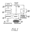
- the proposed system according to the invention divides satellites with near-earth and medium Orbits between different broadcasters on. Every satellite is included the satellite transponder of FIG. 1 equipped with receivers 10 to a via a Receive antenna 11, the DAB transmission multiplex from the uplink stations or from another satellite, e.g. Telecommunications satellites to receive (Fig. 1). about a delay line 20 becomes each received DAB transmission multiplex fed to a COFDM modulator 30, wherein the delay line 20 of a Distance and Doppler control 40 is controlled.
- the delay line 20 Compensates the total running time of the DAB signal, which is composed of the Duration between transmitting station and receiver 10 in the satellite and the term between a transmitter 50 in the satellite and a receiver at a defined one Reference point in the service area.
- the controller 40 which is the delay line 20 controls, therefore detects the distances between uplink station (transmitting station) and Satellite and between satellite and a defined reference point in the Supply area, to from the total signal propagation time of the DAB signal to calculate.
- the controller 40 further controls a variable oscillator 60 (VCO) to to compensate for the Doppler shift with respect to the location of the uplink station.
- VCO variable oscillator
- the detection of the distances and the removal speeds is carried out by Signal processing on board the satellite.
- the COFDM modulated DAB signal at Output of the COFDM modulator 30 is at the output frequency of the variable Oscillator 60 mixed in a mixer 70, whereby the center frequency of the COFDM-modulated DAB signals from the tracked output frequency of the controllable oscillator 60 is determined.
- the satellite transmits the output of the mixer 70 to the receivers in FIG provided coverage area, wherein in the transmitter 50, the COFDM-modulated DAB signals be strengthened.
- the thus radiated DAB broadcasting signal becomes received by the participants in the foundedsbegiet, which is under the Satellite is located.
- the angle of incidence with respect to the satellite coordinate system and the spatial distance to the reference point will be on board the satellite measured and analyzed, as well as the RF frequency deviation of the uplink signal due to the Doppler effect.
- the in the satellite located transmitter 50 is turned on and the COFDM signal is in Direction of the source of the incoming uplink signal sent, as shown in FIG. 2 is apparent.
- the measured on board the satellite Doppler deviation of the received uplink signal is evaluated to the center frequency of the nach motherboard emitted signal.
- the center frequency of the satellite signal is is set by the variable oscillator 60 to such a value as the occurring Doppler deviation at the location of the uplink station exactly to zero compensated.
- the delay time is controlled by evaluation of the distance information, which is the sum of the distance between the location of the satellite and the reference point in the coverage area as well as the distance between the location of the satellite and the place of the uplink station is. This entire signal delay of the DAB signal is kept constant during the active part of the satellite orbit. If necessary, will the on-board satellite transmitter 50 is turned off when the angle of incidence based on the satellite coordinate system falls below a certain threshold.
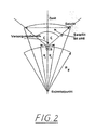
- Fig. 2 From the schematic representation of Fig. 2 it can be seen how the broadcasting satellite transponder is operated or activated within a cone, which is defined by the zenith distance angle ⁇ at the uplink station ULS.
- the location of the uplink station represents the center of the coverage area, which is determined by the angular sectors - ⁇ 1 and + ⁇ 1 relative to the center of the earth.
- the Doppler compensation, the control of the delay time and the switch-off conditions are suitable, soft signal transitions (see Fig. 3) of the to ensure a satellite to one or more other satellites.
- two or more satellites can operate simultaneously without any DAB-symbol interference or unacceptable orthogonality violations of the EUREKA 147-DAB signal type within a coverage area occur.
- the uplink stations have rotationally symmetrical directional antennas with one maximum gain in the vertical direction.
- the bundling of the antennas will open adjusted the fixed angle within which the satellite is active.
- For the production of Information about distance, distance speed and angle of incidence based on the satellite coordinate system aboard the satellite can be transmit appropriate additional signals within the DAB multiplex.
- the uplink stations on the ground can without limitation of the applicability of the method Reference points in the service area and uplink stations in Earth orbits replaced become.
- the orbital data of the satellite system will depend on the respective Requirements regarding the performance at the supply margins, the availability the transmission frequencies and the tolerances of the local elevation angle range selected. There are no restrictions on the inclination, the Eccentricity, the orbital period, the location of the ascending node or the location of the Perigee. Depending on the amount above ground, the number changes for one worldwide, continuous supply required satellite in one area between 10 and 100.
- six broadcasting satellites S 1 provided with the active zenith angle zones of three uplink stations with ULS I, ULS II and ULS III are indicated on the surface of the earth. When the Satellite S 1 of the uplink station ULS I approaches, it is activated.
- the satellite S2 is still active and contributes to the broadcasting in the area of uplink station I.
- the Satellite S3 is active and supplies the area of the uplink station II, whereas the Satellite S4 just leaves the activation cone of the uplink station II and becomes inactive.
- the coverage area of uplink station III is from satellites S5 and S6 supplied simultaneously.
- At one point of an uplink station on the ground may be another Satellite, e.g. Telecommunications satellite, which feeds the signal to the broadcasting satellite.
- the orbital motion of the satellite is circular. Atmospheric or ionospheric Propagation effects are disregarded if the delay times of the DAB symbols, the Doppler effect or the power at the supply margins is calculated become.
- the shape of the earth is assumed to be spherical, with disturbances on Reason for flattening the earth and the Earth's rotation are neglected. On Special geographical areas are not discussed here.
- DAB broadcasting satellites and can be switched off, depending on the occurring Elevation angle in the center of the coverage area.
- the satellite broadcast system can with regard to the RF center frequency (to compensate for Doppler effects) can be controlled and has runtime delay capabilities received uplink signal and to compensate for the changing distances or signal transit times.
- the uplink stations are assumed to work continuously. They have no controllable antennas, so no satellite tracking is done. The signal transfer between each satellite is not directly from the uplink station supported; Rather, the handover process is completely controlled by the satellites in the Orbit controlled.
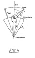
- the profile of the earth's surface below the satellite S within the orbital plane shown in FIG. 4 is represented as a circular arc.
- the origin of the coordinate system is the center of the earth.
- the height of the satellite over ground is indicated by h SAT , the earth radius by R E.
- the uplink station has the polar coordinates 0, R E.
- the satellite Compared with the zenith plotted over the uplink station, the satellite has the zenith angle ⁇ , so that the position of the satellite is given by the polar coordinates ⁇ , R E + h SAT .
- a broadcast coverage area is defined by a segment zone around the uplink station ULS, which is given by the geocentric polar angle ⁇ 1 .
- an adjustable delay line aboard the satellite compensates for the total transit time of the broadcast connection between the uplink station (assumed to be on the ground here) and the satellite and between the satellite and the reference point in the service area.
- the maximum delay time occurs when the satellite S is the ULS uplink station perpendicular (ie in the zenith) passes over.
- the diameter of the possible coverage area as a function of the zenith angle cone, the guard time interval and the satellite orbital altitude is shown in Table 1.
- the size of the service area is of the size depends on the zenith angle cone. If the cone is narrow, the size of the cone increases Coverage area. Meanwhile, the part of the trajectory within which the Satellite can be actively operated, reduced accordingly. For this reason, must a compromise between the size of the coverage area, the number of Satellites in orbit and the minimum elevation angle are taken.
- the speed of a satellite relative to the ground depends on the orbital parameters from.
- For rough estimation of the influence of the Doppler shift on the deterioration of the received EUREKA 147 DAB signal can be some simplistic Assumptions are made. It is sufficient if the considerations be limited to circular paths.
- the Doppler shift occurring at the reference point in the coverage area is fully compensated for by the control of the variable oscillator 60 ( Figure 1) aboard the satellite. This means that compensation errors occur at those locations which do not coincide with the center of the coverage area.
- Table 2 shows the Doppler shift that occurs at the center of the coverage area without compensation aboard the satellite.
- Table 3 shows the remaining difference shift at the edges of the coverage area, assuming that the Doppler shift is compensated for the center of the coverage area aboard the satellite.
- Table 2 shows the occurring maximum absolute value of the Doppler shift ⁇ f as a function of the path height h sat , the diameter D sa of the service area, which is related to the guard time interval ⁇ guard , and the RF center frequency f RF in the center of the service area ( ⁇ f cmax ) or at the supply limits ( ⁇ fb max ).
- Table 3 shows the occurring minimum and maximum values of the Doppler shift in the case of pre-compensation on board the satellite. The values given represent the worst case, as it results for an observer at the supply margins. The explained compensation strategy eliminates the occurring Doppler shift in the center of the coverage area.
- ⁇ , max max ⁇
- the Doppler shift at an RF center frequency of 150 MHz is a Tenths of the values given in Table 3.
- the Doppler shift of the satellite signal is at So obviously the soil is not tolerable without further action as it is serious Violations of the orthogonality of the COFDM signal caused for all DAB modes.
- the Doppler compensation works according to the present Invention sufficiently good, as can be seen from the results for the worst case see Table 3. It turns out that in all places within the Supply area the occurring total frequency change during a Satellite passes at most about 3% of the observed values compared to one missing compensation amounts. If the RF carrier is below 150 MHz, occurs For all DAB modes no significant deterioration of the reception conditions due to orthogonality violations.
- DAB mode # 1 for satellites with near-Earth orbits not suitable; This fashion is due to the multipath propagation on the ground not suitable for L-band transmission anyway.
- the width Opening lobe of the transmitting antenna 51 (Fig. 1), the characteristics of the radio receiver and antenna efficiency.
- the half width of the transmitting antenna 51 to the Supply range is adjusted. This is favorable for frequency reasons, since the spatial repetition of the adjacent channel frequencies is optimal when the spill-over is minimized.
- an efficiency of 0.5 is assumed. In practice, this means that the satellite has a phase-switched array antenna is equipped with the center of the antenna beam on the uplink station or the reference point in the coverage area. Because the direction on this Reference location aboard the satellite is measured or can be calculated is this assumption is realistic.
- the indices indicate the path height with the temperature of the receiving system 400 ° K, the bandwidth 1.536 MHz, the atmospheric attenuation L a 1 dB and the transmission power P 100W.
- N SAT does not depend on the size of the coverage area.
- the orbital parameters are not limited to geosynchronous or geostationary trajectories. Rather, the proposed broadcasting system is available worldwide. Various broadcasters may use the proposed broadcasting system by installing low-cost earth stations (uplink stations) with each other dividing which only the DAB multiplex transmission signal in the vertical direction need to broadcast. Neither a satellite tracking nor a ground control for the signal transfer between the satellites is required in the uplink stations. The achievable coverage areas are large enough for a regional and national Broadcasting coverage.
- the COFDM broadcast signal is provided with a controllable delay device 100 delayed in accordance with the control signal E.
- the output of the Delay device 100 is connected to the first input of a mixer 70, the second input of which is fed by the variable frequency oscillator 200 f.
- the frequency of the oscillator 200 is controlled by a control signal F.
- Of the Output of the mixer 70 is connected to the input of the transmitter 300, which via the transmit antenna 310 with directed antenna lobe 320 to the satellite Broadcast signal feeds.
- the control signal F controls the oscillator 200 so that the from the signal re-radiated to the satellite in the coverage area at the reference point has constant frequency.
- the control signal E controls the delay device 100 such that the total time, formed from the transit time by the delay device 100, the term of the ground to the satellite, the term by the Satellite transponder ( Figure 7) and the transit time from the satellite to the reference point is constant and corresponds to a defined offset value. This compensates for that Control signal E by means of the delay device 100, the runtime changes between the ground and the satellite, due to its relative movement to the satellite Ground spot changes its distance; the control signal F is used to control the Oscillator 200, the Doppler effect of satellite motion relative to a Reference point compensated in the coverage area.
- the transponder differs Fig. 7, characterized in that in the signal branch between the receiver 10 and mixer 70, the Delay 20 and the COFDM modulator 30 are missing. Further, the oscillator 60 becomes as shown in FIG. 7 is not controlled by a controller 40, but runs free.
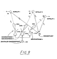
- the structure of the ground location is shown in FIG. From a feed point 400, which is shown with an arrow and the term "broadcast signal" is branched into at least two, otherwise any number of transmit devices 1000, 2000, 3000 and 4000 as shown in FIG. From a common control device 500, the control signals E (for the travel time compensation of the variable distance to the respective satellites S 1 , S 2 ... SJ and F (for the compensation of the Doppler effect) are generated and sent to the transmission devices 1000, 2000, 3000, 4000 ,
- the transmitting devices 1000 and 2000 are the minimum equipment of a ground location for the uninterruptible supply.
- the control device 500 generates control signals for the adjustment of the respective oscillator frequencies f 1 , f 2 ... F n of the oscillators 200, which are variable for the compensation of the Doppler effect, and for the adjustment of the delay devices 100, which the constancy and equality of Establish transit times of all satellite paths between the central feed point 400 of the broadcast signal and the reference point in the coverage area.
- the transmission antennas 310a, 310b ... 310n of the ground location supply the near-earth satellites S 1 , S 2 ... S n within a predetermined zenith angle range to the broadcast signals via directional antennas.
- the transit time through the satellite transponder (FIG. 7) and the transit time from the respective satellite 1, 2... n to the reference point is kept constant and the same for each satellite 1, 2. This situation is illustrated in FIG. 9.
- the delay devices 100a, 100b ... 100n tracked by control signals so that the variable transit time due to the relative movement to the satellites S 1 , S 2 ... S n is compensated.
Claims (2)
- Procédé pour la transmission de signaux radiophoniques modulés en COFDM au moyen d'un système à satellites comprenant plusieurs satellites, lesdits satellites se déplaçant en orbite basse relativement au point de référence dans la zone desservie, procédé selon lequel le signal radiophonique est retardé dans le satellite d'une durée δτDELAY telle que la somme de cette durée δτDELAY et de la durée totale du signal 2·clumière -1·ó(t) dudit signal radiophonique ait une valeur constante τ :
et la durée totale du signal étant composée du temps de propagation entre la station émettrice et le récepteur dans le satellite, ainsi que du temps de propagation entre l'émetteur dans le satellite et un récepteur situé à un point de référence défini dans la zone desservie,
caractérisé en ce que la fréquence médiane des signaux radiophoniques modulés en COFDM, laquelle est soumise à un déplacement Doppler en conséquence du mouvement relatif entre chaque satellite et le point de référence, est guidée de telle façon que la fréquence médiane des signaux radiophoniques reçus par le satellite est constante au point de référence. - Répéteur de satellite pour la réalisation du procédé selon la revendication 1, caractérisé par les caractéristiques suivantes :a) un récepteur, lequel reçoit et, le cas échéant, traite ledit signal radiophonique d'une station émettrice liée à la Terre ou d'un autre satellite ;b) un équipement de retard ayant une durée de retard contrôlable, lequel retarde ledit signal qui a été reçu et, le cas échéant, traité par ledit récepteur d'une durée δτDELAY, en conformité à un signal pilote qui est produit par un dispositif de commande ;c) un oscillateur contrôlable (VCO), dont la fréquence est commandée en conformité audit signal radiophonique ou à un autre signal pilote dudit dispositif de commande de façon à ce qu'au point de référence de ladite zone desservie, la fréquence médiane desdits signaux radiophoniques reçus par ledit satellite soit constante ;d) un modulateur COFDM, lequel module lesdits signaux radiophoniques retardés qui ont été reçus par ledit récepteur et, le cas échéant traités, la fréquence médiane desdits signaux radiophoniques modulés en COFDM étant guidée par ledit oscillateur contrôlable, ete) un émetteur, lequel amplifie lesdits signaux radiophoniques modulés en COFDM et les conduit à une antenne de transmission.
Applications Claiming Priority (2)
| Application Number | Priority Date | Filing Date | Title |
|---|---|---|---|
| DE19618142A DE19618142B4 (de) | 1996-05-06 | 1996-05-06 | Verfahren zum Übertragen von COFDM-modulierten Rundfunksignalen über ein Satellitensystem sowie Satelliten-Transponder zur Durchführung des Verfahrens |
| DE19618142 | 1996-05-06 |
Publications (3)
| Publication Number | Publication Date |
|---|---|
| EP0806850A2 EP0806850A2 (fr) | 1997-11-12 |
| EP0806850A3 EP0806850A3 (fr) | 1999-11-03 |
| EP0806850B1 true EP0806850B1 (fr) | 2005-11-02 |
Family
ID=7793479
Family Applications (1)
| Application Number | Title | Priority Date | Filing Date |
|---|---|---|---|
| EP97103914A Expired - Lifetime EP0806850B1 (fr) | 1996-05-06 | 1997-03-08 | Méthode pour la transmission de signaux de radiodiffusion en modulation par multiplexage par répartition orthogonale de la fréquence codée à travers un système de satellite |
Country Status (3)
| Country | Link |
|---|---|
| EP (1) | EP0806850B1 (fr) |
| AT (1) | ATE308833T1 (fr) |
| DE (2) | DE19618142B4 (fr) |
Family Cites Families (6)
| Publication number | Priority date | Publication date | Assignee | Title |
|---|---|---|---|---|
| US4004098A (en) * | 1973-12-06 | 1977-01-18 | Communications Satellite Corporation (Comsat) | Satellite on-board switching system with satellite-to-satellite link |
| GB9219486D0 (en) * | 1992-09-15 | 1992-10-28 | British Broadcasting Corp | Digital audio broadcasts |
| DE4306590A1 (de) * | 1992-09-21 | 1994-03-24 | Rohde & Schwarz | Digitales Rundfunk-Sendernetz-System |
| JPH0738610B2 (ja) * | 1993-03-01 | 1995-04-26 | 日本電気株式会社 | 周回衛星の送信装置 |
| US5440562A (en) * | 1993-12-27 | 1995-08-08 | Motorola, Inc. | Communication through a channel having a variable propagation delay |
| GB2321831B (en) * | 1994-07-22 | 1999-02-17 | Int Mobile Satellite Org | Satellite communication method and apparatus |
-
1996
- 1996-05-06 DE DE19618142A patent/DE19618142B4/de not_active Expired - Fee Related
-
1997
- 1997-03-08 DE DE59712465T patent/DE59712465D1/de not_active Expired - Lifetime
- 1997-03-08 EP EP97103914A patent/EP0806850B1/fr not_active Expired - Lifetime
- 1997-03-08 AT AT97103914T patent/ATE308833T1/de active
Also Published As
| Publication number | Publication date |
|---|---|
| DE19618142A1 (de) | 1997-11-13 |
| EP0806850A2 (fr) | 1997-11-12 |
| ATE308833T1 (de) | 2005-11-15 |
| DE19618142B4 (de) | 2005-03-17 |
| EP0806850A3 (fr) | 1999-11-03 |
| DE59712465D1 (de) | 2005-12-08 |
Similar Documents
| Publication | Publication Date | Title |
|---|---|---|
| DE60034252T2 (de) | Verfahren und vorrichtung zum selektiven betrieb von satelliten in tundra-umlaufbahnen zur verringerung des bedarfs an empfangspufferspreicher für zeitdiversitätssignale | |
| EP2684299B1 (fr) | Réseau de communication satellitaire | |
| DE60021483T2 (de) | Verfahren und gerät zu herstellung eines breitbanddienstes mit satelliten auf niedriger und mittlerer bahn | |
| DE19747065B4 (de) | Verfahren zur Kommunikation mit Kommunikationsstationen, digitaler Strahlformer und Kommunikationsstation | |
| DE60126792T2 (de) | Aufbau einer zurückverbindung mit begrenzter leistungspektrumsdichte für mobiles satelliten kommunikationssystem | |
| DE60218871T2 (de) | Verfahren und gerät zur wegentdeckung zwischen einer mobilen plattform und einem erdsegment | |
| DE69838272T2 (de) | Verfahren und Anordnung zur Herstellung Breitband Kommunikationen für mobile Benutzer in einem Satelliten Netz | |
| DE3044101C2 (de) | Verfahren zur Erhöhung des Regengrenzwertes einer TDMA-Satellitenfunkanlage und Anlage zur Durchführung des Verfahrens | |
| US6694137B2 (en) | Method and system for providing broadband mobile access from geostationary satellites to platforms using small, low profile antennas | |
| DE69938399T2 (de) | Verfahren und Einrichtung zur Übertragungszeitsteuerung von einem drahtlosen Sender-Empfänger | |
| DE60034163T2 (de) | Anordnung mit Satelliten auf geneigter, exzentrischer geosynchroner Umlaufbahn | |
| DE69724379T2 (de) | Mehrstrahl Antenne, Methode und System zur Generierung von Zellen eines drahtlosen Kommunikationsnetzes, wobei die Mehrstrahlantenne auf einem Luftfahrzeug angeordnet ist | |
| DE69919152T2 (de) | Antennensystem zur verfolgung von nichtgeostationären satelliten | |
| DE19720720A1 (de) | Kommunikationssystem und -verfahren für geosynchrone Satelliten | |
| EP1239608A1 (fr) | Système en diversité de reception des signaux numeriques terrestre et/ou satellite pour voitures | |
| DE60028017T2 (de) | Gerät und verfahren für funkruf in einer satelliten kommunikationsanordnung mit ortsbestimmung des benutzers | |
| DE3820454A1 (de) | Flaechen-nachrichtenuebertragungs-system | |
| DE60213355T2 (de) | Verfahren und Vorrichtung zum Identifizieren, welches einer Vielzahl von mobilen Endgeräten eine Interferenz bzw. Störung mit einem oder mehreren einem Zielsatelliten benachbarten Satelliten verursacht | |
| DE60035737T2 (de) | Verfahren und Anordnung zur Satelliten Kommunikationsbereitstellung durch Gestaltung und Wiedergestaltung der Last auf der Umlaufbahn | |
| EP2684300A1 (fr) | Satellite comportant une pluralité d'antennes directives pour émettre et/ou recevoir des signaux radio de sécurité aérienne | |
| DE60024733T2 (de) | System zum Ausrichten einer Satellitenantenne | |
| US6078286A (en) | Method and apparatus for efficient acquisition and tracking of satellites | |
| EP0806850B1 (fr) | Méthode pour la transmission de signaux de radiodiffusion en modulation par multiplexage par répartition orthogonale de la fréquence codée à travers un système de satellite | |
| DE69936427T2 (de) | Verfahren und Gerät zur InitiaIisierung des Kommunikationsnetzes zur schnellen Bestimmung der GPS Position | |
| DE69914945T2 (de) | Telekommunikationsgerät mit geformter gruppenantenne unter verwendung von elektronischer strahlschwenkung und dazugehöriges telekommunikations-endgerät |
Legal Events
| Date | Code | Title | Description |
|---|---|---|---|
| PUAI | Public reference made under article 153(3) epc to a published international application that has entered the european phase |
Free format text: ORIGINAL CODE: 0009012 |
|
| AK | Designated contracting states |
Kind code of ref document: A2 Designated state(s): AT BE CH DE DK ES FI FR GB GR IE IT LI LU NL PT SE |
|
| AX | Request for extension of the european patent |
Free format text: SI PAYMENT 970402 |
|
| PUAL | Search report despatched |
Free format text: ORIGINAL CODE: 0009013 |
|
| AK | Designated contracting states |
Kind code of ref document: A3 Designated state(s): AT BE CH DE DK ES FI FR GB GR IE IT LI LU NL PT SE |
|
| AX | Request for extension of the european patent |
Free format text: SI PAYMENT 19970402 |
|
| 17P | Request for examination filed |
Effective date: 19991221 |
|
| 17Q | First examination report despatched |
Effective date: 20040405 |
|
| GRAP | Despatch of communication of intention to grant a patent |
Free format text: ORIGINAL CODE: EPIDOSNIGR1 |
|
| GRAS | Grant fee paid |
Free format text: ORIGINAL CODE: EPIDOSNIGR3 |
|
| GRAA | (expected) grant |
Free format text: ORIGINAL CODE: 0009210 |
|
| AK | Designated contracting states |
Kind code of ref document: B1 Designated state(s): AT BE CH DE DK ES FI FR GB GR IE IT LI LU NL PT SE |
|
| AX | Request for extension of the european patent |
Extension state: SI |
|
| PG25 | Lapsed in a contracting state [announced via postgrant information from national office to epo] |
Ref country code: IT Free format text: LAPSE BECAUSE OF FAILURE TO SUBMIT A TRANSLATION OF THE DESCRIPTION OR TO PAY THE FEE WITHIN THE PRE;WARNING: LAPSES OF ITALIAN PATENTS WITH EFFECTIVE DATE BEFORE 2007 MAY HAVE OCCURRED AT ANY TIME BEFORE 2007. THE CORRECT EFFECTIVE DATE MAY BE DIFFERENT FROM THE ONE RECORDED.SCRIBED TIME-LIMIT Effective date: 20051102 Ref country code: IE Free format text: LAPSE BECAUSE OF FAILURE TO SUBMIT A TRANSLATION OF THE DESCRIPTION OR TO PAY THE FEE WITHIN THE PRESCRIBED TIME-LIMIT Effective date: 20051102 Ref country code: GB Free format text: LAPSE BECAUSE OF FAILURE TO SUBMIT A TRANSLATION OF THE DESCRIPTION OR TO PAY THE FEE WITHIN THE PRESCRIBED TIME-LIMIT Effective date: 20051102 Ref country code: FI Free format text: LAPSE BECAUSE OF FAILURE TO SUBMIT A TRANSLATION OF THE DESCRIPTION OR TO PAY THE FEE WITHIN THE PRESCRIBED TIME-LIMIT Effective date: 20051102 |
|
| REG | Reference to a national code |
Ref country code: GB Ref legal event code: FG4D Free format text: NOT ENGLISH |
|
| REG | Reference to a national code |
Ref country code: CH Ref legal event code: EP |
|
| REF | Corresponds to: |
Ref document number: 59712465 Country of ref document: DE Date of ref document: 20051208 Kind code of ref document: P |
|
| PG25 | Lapsed in a contracting state [announced via postgrant information from national office to epo] |
Ref country code: SE Free format text: LAPSE BECAUSE OF FAILURE TO SUBMIT A TRANSLATION OF THE DESCRIPTION OR TO PAY THE FEE WITHIN THE PRESCRIBED TIME-LIMIT Effective date: 20060202 Ref country code: GR Free format text: LAPSE BECAUSE OF FAILURE TO SUBMIT A TRANSLATION OF THE DESCRIPTION OR TO PAY THE FEE WITHIN THE PRESCRIBED TIME-LIMIT Effective date: 20060202 Ref country code: DK Free format text: LAPSE BECAUSE OF FAILURE TO SUBMIT A TRANSLATION OF THE DESCRIPTION OR TO PAY THE FEE WITHIN THE PRESCRIBED TIME-LIMIT Effective date: 20060202 |
|
| PG25 | Lapsed in a contracting state [announced via postgrant information from national office to epo] |
Ref country code: ES Free format text: LAPSE BECAUSE OF FAILURE TO SUBMIT A TRANSLATION OF THE DESCRIPTION OR TO PAY THE FEE WITHIN THE PRESCRIBED TIME-LIMIT Effective date: 20060213 |
|
| REG | Reference to a national code |
Ref country code: CH Ref legal event code: NV Representative=s name: PATENTANWAELTE SCHAAD, BALASS, MENZL & PARTNER AG |
|
| PG25 | Lapsed in a contracting state [announced via postgrant information from national office to epo] |
Ref country code: PT Free format text: LAPSE BECAUSE OF FAILURE TO SUBMIT A TRANSLATION OF THE DESCRIPTION OR TO PAY THE FEE WITHIN THE PRESCRIBED TIME-LIMIT Effective date: 20060403 |
|
| GBV | Gb: ep patent (uk) treated as always having been void in accordance with gb section 77(7)/1977 [no translation filed] |
Effective date: 20051102 |
|
| REG | Reference to a national code |
Ref country code: IE Ref legal event code: FD4D |
|
| ET | Fr: translation filed | ||
| PLBE | No opposition filed within time limit |
Free format text: ORIGINAL CODE: 0009261 |
|
| STAA | Information on the status of an ep patent application or granted ep patent |
Free format text: STATUS: NO OPPOSITION FILED WITHIN TIME LIMIT |
|
| 26N | No opposition filed |
Effective date: 20060803 |
|
| REG | Reference to a national code |
Ref country code: FR Ref legal event code: PLFP Year of fee payment: 19 |
|
| PGFP | Annual fee paid to national office [announced via postgrant information from national office to epo] |
Ref country code: CH Payment date: 20150319 Year of fee payment: 19 Ref country code: DE Payment date: 20150323 Year of fee payment: 19 Ref country code: NL Payment date: 20150319 Year of fee payment: 19 Ref country code: LU Payment date: 20150319 Year of fee payment: 19 |
|
| PGFP | Annual fee paid to national office [announced via postgrant information from national office to epo] |
Ref country code: AT Payment date: 20150323 Year of fee payment: 19 Ref country code: FR Payment date: 20150319 Year of fee payment: 19 |
|
| PGFP | Annual fee paid to national office [announced via postgrant information from national office to epo] |
Ref country code: BE Payment date: 20150318 Year of fee payment: 19 |
|
| PG25 | Lapsed in a contracting state [announced via postgrant information from national office to epo] |
Ref country code: BE Free format text: LAPSE BECAUSE OF NON-PAYMENT OF DUE FEES Effective date: 20160331 |
|
| REG | Reference to a national code |
Ref country code: DE Ref legal event code: R119 Ref document number: 59712465 Country of ref document: DE |
|
| PG25 | Lapsed in a contracting state [announced via postgrant information from national office to epo] |
Ref country code: LU Free format text: LAPSE BECAUSE OF NON-PAYMENT OF DUE FEES Effective date: 20160308 |
|
| REG | Reference to a national code |
Ref country code: CH Ref legal event code: PL |
|
| REG | Reference to a national code |
Ref country code: AT Ref legal event code: MM01 Ref document number: 308833 Country of ref document: AT Kind code of ref document: T Effective date: 20160308 |
|
| REG | Reference to a national code |
Ref country code: NL Ref legal event code: MM Effective date: 20160401 |
|
| REG | Reference to a national code |
Ref country code: FR Ref legal event code: ST Effective date: 20161130 |
|
| PG25 | Lapsed in a contracting state [announced via postgrant information from national office to epo] |
Ref country code: CH Free format text: LAPSE BECAUSE OF NON-PAYMENT OF DUE FEES Effective date: 20160331 Ref country code: FR Free format text: LAPSE BECAUSE OF NON-PAYMENT OF DUE FEES Effective date: 20160331 Ref country code: LI Free format text: LAPSE BECAUSE OF NON-PAYMENT OF DUE FEES Effective date: 20160331 Ref country code: NL Free format text: LAPSE BECAUSE OF NON-PAYMENT OF DUE FEES Effective date: 20160401 Ref country code: DE Free format text: LAPSE BECAUSE OF NON-PAYMENT OF DUE FEES Effective date: 20161001 |
|
| PG25 | Lapsed in a contracting state [announced via postgrant information from national office to epo] |
Ref country code: AT Free format text: LAPSE BECAUSE OF NON-PAYMENT OF DUE FEES Effective date: 20160308 |