EP0806845B1 - Verfahren und Gerät zur Kommunikationssynchronisation in einer Satellitenkommunikationsanordnung - Google Patents
Verfahren und Gerät zur Kommunikationssynchronisation in einer Satellitenkommunikationsanordnung Download PDFInfo
- Publication number
- EP0806845B1 EP0806845B1 EP97106565A EP97106565A EP0806845B1 EP 0806845 B1 EP0806845 B1 EP 0806845B1 EP 97106565 A EP97106565 A EP 97106565A EP 97106565 A EP97106565 A EP 97106565A EP 0806845 B1 EP0806845 B1 EP 0806845B1
- Authority
- EP
- European Patent Office
- Prior art keywords
- earth station
- user terminal
- synchronization
- data
- slave
- Prior art date
- Legal status (The legal status is an assumption and is not a legal conclusion. Google has not performed a legal analysis and makes no representation as to the accuracy of the status listed.)
- Expired - Lifetime
Links
- 238000004891 communication Methods 0.000 title claims description 61
- 238000000034 method Methods 0.000 title claims description 22
- 230000001360 synchronised effect Effects 0.000 claims description 27
- 238000012544 monitoring process Methods 0.000 claims description 4
- 238000001228 spectrum Methods 0.000 claims 1
- 230000005540 biological transmission Effects 0.000 description 18
- 230000000694 effects Effects 0.000 description 7
- 239000002131 composite material Substances 0.000 description 4
- 238000005259 measurement Methods 0.000 description 4
- 230000010267 cellular communication Effects 0.000 description 2
- 230000007423 decrease Effects 0.000 description 2
- 238000010586 diagram Methods 0.000 description 2
- 230000001413 cellular effect Effects 0.000 description 1
- 238000012937 correction Methods 0.000 description 1
- 230000001934 delay Effects 0.000 description 1
- 230000002452 interceptive effect Effects 0.000 description 1
- 230000010363 phase shift Effects 0.000 description 1
- 238000012545 processing Methods 0.000 description 1
Images


Classifications
-
- H—ELECTRICITY
- H04—ELECTRIC COMMUNICATION TECHNIQUE
- H04B—TRANSMISSION
- H04B7/00—Radio transmission systems, i.e. using radiation field
- H04B7/14—Relay systems
- H04B7/15—Active relay systems
- H04B7/204—Multiple access
- H04B7/212—Time-division multiple access [TDMA]
- H04B7/2125—Synchronisation
Definitions
- the present invention generally relates to a satellite based telecommunication system. More specifically, the present invention relates to synchronization of forward and return communications links between user terminals and earth stations.
- Satellite based telecommunications systems have been proposed for enabling user terminals to communicate with one another and with an existing public telephone switching network (PSTN).
- PSTN public telephone switching network
- the user terminals interconnect with one another and with the public telephone network through earth stations strategically located at predefined geographic positions about the earth.
- the proposed systems utilize a constellation of telecommunications satellites for relaying communications signals between the user terminals and earth stations. These communications signals pass along predefined channels uniquely assigned to each user terminal. Each channel includes a forward link along which an earth station transmits RF signals to a mobile terminal and a return link along which the user terminal transmits RF signals to the earth station. Each communications link passes through a corresponding satellite which functions as a "bent pipe” and retransmits all received communications to the corresponding earth station or user terminal.
- satellite based telecommunications systems utilize one or more coding techniques to enhance the system capacity.
- the system may employ frequency division multiple access (FDMA) coding, time division multiple access (TDMA) coding, code division multiple access (CDMA) coding, or any combination of FDMA, TDMA, and CDMA coding.
- FDMA frequency division multiple access
- TDMA time division multiple access
- CDMA code division multiple access
- the earth station synchronizes in frequency and timing each return link assigned thereto in order to prevent interference between transmissions emitted from different user terminals.
- the transmissions from multiple user terminals must be emitted at predefined times to ensure that the transmissions are received by a common earth station simultaneously. Variations in timing result as the distance varies between a coverage satellite and a transmitting user terminal.
- the transmission arrives later in time at the earth station.
- the transmission arrives earlier in time.
- the user terminals are controlled to retard and advance the starting times for data transmissions (i.e., frames of communications data) to ensure that frames from multiple user terminals assigned to a common earth station arrive at the earth station simultaneously.
- each earth station controls user terminals assigned thereto in order to ensure that the return link remains centered about an assigned carrier frequency (i.e., sub-band) as received at the earth station.
- the center frequency of each transmission from a user terminal experiences frequency changes due to the Doppler effect.
- the Doppler effect occurs due to the fact that a satellite continuously moves relative to a transmitting user terminal.
- the perceived carrier frequency of the receiver increases as the satellite moves toward a user terminal and decreases as the satellite moves away from the user terminal. If not corrected, Doppler induced frequency shifts and timing misalignment create co-channel interference between transmissions received from multiple user terminals.
- the user terminals continuously adjust the carrier frequency and timing of outgoing transmissions to ensure that the perceived carrier frequency and timing at the assigned earth station receiver equals the assigned carrier frequency and timing for the user terminal.
- a need remains for accurately maintaining the forward and return links between an earth station and user terminal.
- a need remains to facilitate handovers.
- satellites continuously orbit the earth.
- the user terminals may also move. Consequently, a communications link with a user terminal may need to be transferred or handed over from one earth station to another earth station.
- the user terminal When a handover occurs, the user terminal must be changed to a new channel in which it establishes new forward and return links between the user terminal and the new earth station. This adjustment includes changing the timing of the user terminal to align with the new earth station's reference time.
- the user terminal transmitter must also shift to a new carrier frequency.
- past systems have been unable to provide earth station sharing wherein multiple earth stations communicate with a user terminal at the same time through a common satellite.
- Earth station sharing requires timing and frequency alignment at the common user terminal of RF signals from both earth stations. Such alignment is complicated due to the presence of differing earth station to satellite path links and Doppler variations.
- existing systems have been unable to provide return link synchronization with earth station sharing in which user terminals commmunicate in a common subband through a common satellite to multiple earth stations. To do so, the received communications signals must be aligned in time and frequency at any earth station receiving such signals.
- a need remains within the industry for an improved telecommunications system capable of maintaining synchronization between multiple user terminals and sharing earth stations. It is an object of the present invention to meet this need.
- US-3,654,395 discloses to synchronize signals transmitted from two or more earth stations.
- the satellite transmits the received signals to a further earth station.
- the further earth station detects synchronization signals contained in each of the received signals.
- the further earth station compares these synchronization signals in time to a reference signal.
- the reference signal can be provided by one of the at least two earth stations or the further earth station.
- the further earth station generates error signals for each received signal representing the respective deviation thereof from the reference signal.
- the further earth station transmits the error signals via the satellite to the respective ones of the at least two earth stations.
- EP 0 578 506 A2 discloses synchronization of a first base station in a cellular communications environment with respect to a second base station. Synchronization is obtained on the basis of signals transmitted from a mobile station to the second base station. These signals include synchronization signals concerning synchronization of the mobile station and the second base station. The signals from the mobile station are also received by the first base station. The first base station obtains from the received mobile station synchronization signals and adjusts its timing in view of the obtained synchronization signals. As a result, the second base station is synchronized with respect to the first base station.
- WO 94/30024 discloses synchronization of base stations in a cellular telecommunications environment as regards forward communications links to a mobile station.
- the mobile station being in communication with a first base station receives first base station signals via a first forward communications link. Further, the mobile station receives signals from a second base station via a second forward communications link.
- the mobile station determines a timing difference between the first and second base station signals. The timing difference is transmitted from the mobile station to a facility of the cellular communications environment. On the basis of the timing difference, the facility controls the second base station to operate in synchronized manner with respect to the first base station.
- US-4,577,316 discloses synchronization between at least two earth stations in a satellite based communications system.
- One of the earth stations is designated as master earth station.
- Each earth station transmits a signal to a satellite.
- timing differences between the signal of the master earth station and signals from other earth stations are determined with respect to the master earth station signal.
- the timing differences are transmitted from the satellite to respective earth stations not including the master earth station.
- each of the receiving earth stations adjusts its transmissions to accomplish synchronization with respect to the master earth station.
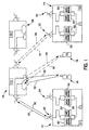
- Fig. 1 generally illustrates a sub-section of a satellite based telecommunications system including a satellite 10 , earth stations 12 and 14 and user terminals 16 and 18 .
- Earth stations 12 and 14 include antennas 20 and 22 for tracking the satellite 10 . Additional antennas 24 and 26 are provided for tracking a second satellite 28 .
- Earth station 12 communicates with user terminal 16 via a forward link 30 and a return link 32 .
- the forward and return links 30 and 32 pass through the satellite 10 which functions as a bent pipe to retransmit all communications received.
- Earth station 14 communicates with user terminal 18 via forward and return links 34 and 36 , respectively.
- the earth stations and user terminals pass communications data and command information along the forward and return links in sequential discrete frames.
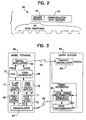
- Fig. 2 illustrates an exemplary format for a communications frame 38 .
- the frame 38 may include a header section 40 followed by a data section 42 .
- the data section 42 may include telecommunications data and/or commands, while the header section 40 may include a synchronization field having synchronization information necessary to maintain synchronous communications along the forward and return links 30-36 .
- the header and data sections 40 and 42 may be configured in a variety of formats.
- the data section may include one or more PN codes, CDMA codes and similar signature waveforms which uniquely identify user terminals to which or from which the data is directed. Communications data may be modulated with the signature waveform of the user terminal transmitting or intended to receive the data.
- a frame 38 transmitted from a user terminal 16 only contains communications data related to that user terminal and accordingly, the data section 42 includes data modulated with the single corresponding signature waveform.
- a frame 38 transmitted by an earth station may include communications data sets directed to multiple user terminals. If so, the data section 42 is assembled by superimposing multiple data signals upon one another. Each data signal is modulated with a corresponding unique user terminal signature waveform to provide a composite communications data signal.
- the header section 40 may include a sync field 44 configured to hold one or more synchronization waveforms.
- frames transmitted by a user terminal include a single unique synchronization waveform.
- Frames transmitted from earth stations may include multiple synchronization waveforms superimposed upon one another within the sync field 44 .
- Each synchronization waveform corresponds to a signature waveform and communications data set in the data section 44.
- the present invention utilizes synchronous communications links in the forward and return directions. Communications signals are considered “synchronous" when the transmitter is controlled to ensure that a frame of communications data is received at a predefined point in time and at the nominal carrier frequency. With reference to Fig. 1, the forward link 30 from earth station 12 is considered to be synchronous since the earth station 12 transmits superimposed communications data for multiple user terminals 16 and 18 in a single frame. The overlapping data is aligned or "synchronized" within the communications data section 42.
- the return links 32 and 36 are considered synchronous when multiple user terminals, such as terminals 16 and 18 , are controlled to transmit frames of communications data such that both frames are received simultaneously by the earth station 12 and synchronous with respect to a reference time and frequency.
- the earth stations 12 and 14 include modulator and demodulator banks 50 and 52 respectively.
- the demodulators in bank 52 operate to separate communications data for each desired user terminal from the composite communications frame.
- the modulator bank 50 operates to combine, into a composite frame, communications data for multiple user terminals.
- Fig. 3 illustrates the components of a user terminal 60 and earth station which cooperate to maintain a synchronous return link 64 therebetween. While not illustrated in Fig. 3, it is understood that the return link 64 progresses via a satellite.
- the user terminal 60 includes a demodulator 67 which locks onto and tracks an incoming RF signal received from forward link (FL) 65 .
- the demodulator 67 demodulates the incoming RF signal to obtain encoded frequency and timing error offset signals therefrom.
- the encoded frequency and timing error offset signals are embedded in the incoming RF signal as explained below.
- the demodulator 67 effects demodulation based on an estimated RF carrier frequency and an estimated timing (e.g., code chip timing) with respect to the user terminal's reference oscillator (not shown).
- the reference oscillator generates reference signals upon which all modulation and demodulation are based.
- the demodulator estimated frequency and timing are output along lines 73 and 75 , respectively, to transmission frequency and code calculation modules 77 and 79 , respectively.
- the demodulator 67 outputs the encoded frequency and timing error offset signals to frequency and code loop filters 74 and 76 , respectively.
- the error signals may represent bit streams.
- the frequency and code loop filters 74 and 76 may output average values for a plurality of received error offset signals.
- the outputs of the loop filters 74 and 76 are delivered to the transmission frequency and code calculation modules 77 and 79 , respectively.
- the frequency and code calculation modules 77 and 79 combine corresponding input frequencies and chip timing codes to correct for Doppler shifts and range variations between the satellite and the user terminal.
- the frequency and code calculation modules 77 and 79 may combine corresponding input signals to correct for error within the modulation/demodulation reference oscillator of the user terminal.
- the frequency and code calculation modules 77 and 79 may produce sums of, or differences between, corresponding inputs.
- the frequency and code calculation modules 77 and 79 output the frequency and coding signals to the oscillator 70 and code generator 68 , respectively.
- the user terminal 60 also includes a signal modulator 66 which transmits communications frames (structured as shown in Fig. 2).
- the modulator 66 operates at a carrier frequency defined by the oscillator 70 and at a chip timing defined by the code generator 68 .
- the oscillator 70 may adjust its output carrier frequency based on the output of transmission frequency calculation module 77 .
- the modulator 66 may combine outgoing communications data with a signature waveform produced by the waveform generator 68 .
- a modulated combination of the data and signature waveform may be transmitted in the communications data section 42 of a frame.
- the waveform generator 68 may produce a synchronization waveform which is inserted into the sync field of the header section 40 of the frame 38 .
- the synchronization waveform may be part of, or separate from, the signature waveform.
- the generator 68 produces the sync and signature waveforms based on the output of the transmission code calculation module 79 . These components cooperate to retard or advance the transmission starting time for each frame 38 and to define the central carrier frequency and corresponding sub-band within which the communications frame 38 is transmitted over the return link 64 .
- the user terminal and earth station of Fig. 3 maintain synchronization through a closed loop control process whereby the earth station 62 continuously provides, via the forward link 65 , timing and frequency update information.
- the earth station 62 includes at least one demodulator 80 to demodulate the composite communications signal within the communications section of each frame 38 .
- the demodulator 80 outputs the communications data transmitted by user terminal 60 based on the signature waveforms imbedded within the received RF signal.
- the incoming RF signal may include multiple data and sync waveforms from an equal number of user terminals, the following explanation is only provided with respect to a single user terminal. The following process and structure merely need be repeated for the portion of the RF signal corresponding to other user terminals.
- the earth station 62 includes timing and frequency discriminators 82 and 84 .
- the timing discriminator 82 compares the sync waveform from the sync field 44 of each frame with a timing reference signal to obtain a timing offset error therebetween.
- the timing offset error represents the amount by which the synchronization waveform in the received sync field varies, in time, from the timing reference signal. This offset error represents the amount by which the user terminal must advance or retard its timing to properly align subsequent frames with the reference time of the earth station 62 .
- the code timing discrimination may be effected through auto correlation of the reference and received timing signals, such as through calculating the dot product of the received and reference signals and the like.
- a frequency discriminator 84 compares the received synchronization waveform with a frequency reference signal to determine the amount by which the received signal in return link 64 has shifted from the assigned carrier frequency (i.e., assigned sub-band). Frequency discrimination may be effected through a variety of known techniques, such as by converting the received and reference signals to the frequency domain and comparing phase shifts therebetween. The frequency discriminator 84 generates a frequency error offset representing the amount by which the user terminal 60 must shift its carrier frequency to properly align the return link 64 within its assigned sub-band centered about its assigned carrier frequency.
- the timing and frequency error offsets are transmitted via a forward link 65 (through a satellite not shown) to the user terminal 60 .
- the timing and frequency error signals are delivered to code and frequency filters 74 and 76 .
- the filters 74 and 76 may receive multiple error signals through return link 65 and separately average multiple timing and frequency error signals.
- the averages of the timing error signals are supplied to the code generator 68 .
- the average of the frequency error signals are supplied to the oscillator 70 .
- the oscillator 70 and generator 68 adjust the carrier frequency and timing by an amount equal to the received error offsets. In this manner, the user terminal 60 retains a synchronized return link 64 with its associated earth station 62.
- the foregoing path between the user terminal 60 and earth station 62 represents an active closed loop architecture to correct for propogation delays and Doppler effects unique to the transmitting user terminal 60 .
- This timing and frequency correction process is performed independently for each user terminal communicating with the earth station 62 . In this manner, all frames arriving at the earth station are aligned in time and frequency.
- Figs. 4-6 illustrate a system in which return link synchronization is maintained between multiple earth stations.
- a system controller assigns one master earth station to each satellite 106 , while all other earth stations covered by the satellite operate as slave earth stations with respect to this common satellite. As satellites orbit, they cover different earth stations. The master earth station is reassigned for a satellite each time the satellite's coverage area moves beyond its previous master earth station. Once assigned, an earth station may remain as the master earth station for a given satellite until the coverage area passes beyond the master earth station. An earth station may be assigned as the master earth station based on several criteria, such as geographic location, duration within the satellite's field of view (coverage area), access to the public switching telephone network, and the like. Once a master earth station is assigned to a satellite, all other earth stations entering and leaving that satellite's field of view are slaves. This assignment is performed separately with respect to each satellite. Thus, while in an overlap region between multiple satellites, an earth station may be a slave with respect to one satellite and simultaneously a master with respect to another satellite.
- Fig. 4 illustrates master and slave earth stations 100 and 102 which have been assigned in connection with a common satellite 106 .
- the master earth station 100 receives communications from a user terminal 104 via a return link 108 .
- the slave earth station 102 continuously monitors the return link 108 (as illustrated by dashed line 110 ).
- the satellite 106 transmits RF signals received from user terminal 104 along the feeder links to all earth stations in the satellite's field of view. While the user terminal 104 may only retain a forward link 108 with the master earth station 100 , the RF signals are transmitted by the satellite toward all slave earth stations. By monitoring return link 108 , the slave earth station 102 is able to intercept RF signals traveling to the master earth station 100 . As explained below in connection with Figs. 5 and 6, the slave earth station 102 updates its internal timing and frequency reference signals to maintain synchronization with the return link 108 of the user terminal 104 .
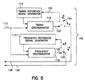
- Fig. 5 illustrates a subsection of the slave earth station 102 which operates in connection with shared return link synchronization.
- the RF signals passed along return link 108 are received on line 110 and supplied to timing and frequency discriminators 116 and 118 .
- the discriminators 116 and 118 compare the received communication signal on line 110 with reference signals from timing and frequency signal generators 112 and 114 to obtain timing and frequency offset error signals which are output at lines 120 and 122 .
- the timing and frequency offset error signals are delivered to switches 124 and 126 .
- the timing and frequency offset error signals are delivered along lines 128 and 129 .
- the offset error signals are delivered along a forward link ( 65 in Fig. 3) to resultant user terminals to synchronize the return link 64 .
- the switches 124 and 126 are rotated in the direction of arrows B to connect with input lines 130 and 132 which deliver the offset error signals to corresponding return link timing and frequency signal generators 112 and 114 .
- the timing and frequency reference signal generators 112 and 114 are updated based upon the incoming error offset signals on lines 130 and 132 such that the signal generators produce timing and frequency reference signals synchronized with the incoming timing and frequency received on line 110 .
- the timing and frequency reference signal generators 112 and 114 control the timing and carrier frequency of outgoing frames transmitted by the user terminal 113 along a return link 111 to the assigned slave earth station 102 .
- the generators 112 and 114 adjust to align with the received timing and frequency of the RF signal from user terminal 104 , they similarly align return link 111 from user terminal 113 .
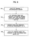
- Fig. 6 illustrates the return link synchronization process.
- the user terminal 104 transmits a communications frame along the return link 108 (Fig. 4) to the master earth station 100 .
- This communications frame is monitored by the slave earth station 102 via link 110 (at step 202 ).
- the slave earth station calculates the timing and frequency offsets (within discriminators 116 and 118 ) between the received frame and the slave earth station's reference timing and frequency signals (step 204 ) from generators 112 and 114 .
- the switches 124 and 126 are moved in the direction of arrows B, the slave earth station updates its reference timing and frequency generators 112 and 114 to be synchronous with the received RF signal of return link 108 .
- the slave earth station subsequently adjusts return link synchronization of all user terminals ( 113 ) assigned thereto.
- the subsystem of earth stations and user terminals serviced by satellite 106 are synchronized with respect to a single master earth station 100 .
- This synchronization sequence is carried out by first synchronizing the return link 108 of the user terminal 104 with the master earth station 100 . Thereafter, the slave earth station 102 adjusts its timing and frequency return link reference signals to be synchronous with the return link 108 .
- the slave earth station 102 instructs the user terminal 113 assigned to the slave earth station 102 to adjust its return link timing and frequency in order to be synchronous with the updated timing and frequency reference signal generators 112 and 114 .
- the return link user terminal 113 assigned to the slave earth station 102 becomes synchronous with the return link 108 to master earth station 100 .
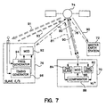
- Fig. 7 illustrates a system in which forward links from multiple earth stations 72 and 76 in a common satellite's 74 field of view are synchronized.
- the earth stations 72 and 76 transmit to the user terminal 70 via forward links 78 and 80 .
- the user terminal 70 transmits along a return link 90 which is received by earth stations 72 and 76 . While the embodiment illustrated in Fig. 7 shows forward and return links between earth stations 72 and 76 and the common user terminal 70 , the user terminal 70 maintains a single communications link at any given instant. In the example of Fig. 7, the user terminal 70 and earth station 72 maintain forward and return communications links 78 and 90 until the user terminal 70 is handed off to earth station 76 .
- user terminal 70 Upon completion of the handoff, user terminal 70 only maintains forward and return links 80 and 81 with the earth station 76 . While forward and return links 78 and 90 are maintained with earth station 72 , the earth station 76 monitors the return link 90 (as shown by line 91).
- the earth stations are configured as master and slave earth stations 70 and 72 , respectively. While two earth stations are illustrated, it is understood that any number of earth stations may be within the field of view of the common satellite 74 . All earth stations which communicate via satellite 74 may be considered to represent an earth station sharing subsystem within which a single earth station is assigned as the master station and all remaining earth stations are assigned as slave stations with respect to communications links passing through satellite 74 .
- each earth station may communicate with more than one satellite. Accordingly, an earth station may represent a master station with respect to a first satellite while operating as a slave station with respect to a second satellite.
- station 72 has been assigned as the master earth station and as such, maintains a closed synchronization loop (as explained above in connection with Figs. 1-3) with the user terminal 70 .
- the master earth station 72 adjusts the timing and frequency of the user terminal 70 until synchronous with the master earth station's timing and frequency reference signals.
- the slave earth station 76 transmits a synchronization update request along feeder link 80 to the user terminal 70 .
- the user terminal 70 includes two receivers and at least one transmitter. Thus, the user terminal 70 may receive RF signals upon two separate forward channels.
- the user terminal 70 receives the update request from slave earth station 76 via the second receiver, without interfering with the forward link 78 with master earth station 72 .
- the request instructs the user terminal 70 to perform a differential timing and frequency measurement between the forward links 78 and 80 of the master and slave earth stations 72 and 76 .
- the user terminal 70 passes a communications frame received upon forward link 78 to a master demodulator 82 and passes a communications frame received upon forward link 80 to slave demodulator 84 .
- the master demodulator 82 compares the received master synchronization waveform with a stored synchronization waveform to determine timing and frequency differences therebetween.
- the slave demodulator 84 compares the received slave synchronization waveform with a reference synchronization waveform to obtain timing and frequency offset signals therebetween.
- these timing and frequency differences may simply represent the timing and frequency error offset signals (as explained above in connection with Fig. 3).
- the demodulated master and slave timing and frequency waveform signals are passed to a comparator which obtains differences therebetween.
- the differential timing and differential frequency obtained by comparator 88 are passed to modulator 86 and transmitted upon the return link 90 .
- the slave earth station 76 monitors the return link 90 to obtain this differential timing and frequency information along line 91 . Thereafter, the slave earth station 76 adjusts its forward link timing and frequency reference signals based on the differential timing and frequency measurements received on line 91 . In this manner, signals passed along forward link 80 become synchronized at the user terminal 70 with signals passed along forward link 78 .
- the slave earth station 76 includes a modulator 92 which transmits along link 80 .
- the modulator operates based on a carrier frequency generated by the frequency generator 94 and based upon a timing signal generated by the timing generator 96 .
- the frequency and timing generators 94 , 96 are set based on the differential timing and frequency measurements transmitted by the user terminal 70 and monitored along link 91 .
- forward and return link synchronization with earth station sharing are achieved by assigning one earth station as the master and the remaining earth stations viewed from a common satellite as slaves.
- the slave earth stations align their forward and return links relative to the master earth station's forward and return links to maintain synchronization at the common user terminal. While multiple common user terminals may be used, only one of the common user terminals need be monitored by the slave earth station to maintain synchronization with the master earth station. This process is repeated at a rate consistent with the dynamic effects being tracked and the required level of accuracy.
Landscapes
- Engineering & Computer Science (AREA)
- Computer Networks & Wireless Communication (AREA)
- Signal Processing (AREA)
- Radio Relay Systems (AREA)
- Synchronisation In Digital Transmission Systems (AREA)
- Mobile Radio Communication Systems (AREA)
Claims (16)
- Teilsystem eines satellitengestützten Telekommunikationssystems zur Aufrechterhaltung einer synchronen Nachrichtenverbindung zwischen einem Nutzerendgerät und mindesten zwei Erdfunkstellen, wobei das Teilsystem enthält:wobei das Nutzerendgerät (70) einen Modulator (86) zum Erzeugen der Datenrahmen (38) basierend auf den Differenzdaten enthält, um die rückwärts gerichtete Nachrichtenverbindung (32) synchron mit den Bezugssynchronisationsdaten der Erdfunkstelle zu halten, wobeieine Erdfunkstelle (72) zum Empfangen von Telekommunikationsdatenrahmen (38), um davon empfangene Synchronisationsdaten zu erlangen, um Differenzdaten zwischen den erlangten Synchronisationsdaten und Bezugssynchronisationsdaten der Erdfunkstelle (72) zu berechnen und um die Differenzdaten entlang einer vorwärts gerichteten Nachrichtenverbindung (78) an das Nutzerendgerät (70) zu übertragen,das Nutzerendgerät (70) zum Übertragen der Datenrahmen (38) entlang einer rückwärts gerichteten Nachrichtenverbindung (32) an die Erdfunkstelle (72), und
die Erdfunkstelle (72) als Haupterdfunkstelle (72) bestimmt ist mit den Bezugssynchronisationsdaten als Hauptbezugssynchronisationsdaten,
das Nutzerendgerät (70) der Haupterdfunkstelle (72) zugeordnet wird, wobei das Nutzerendgerät synchron mit der Haupterdfunkstelle (72) über mindestens eine der vorwärts gerichteten Verbindung (78) und der rückwärts gerichteten Verbindung (90) kommuniziert,
wobei das Teilsystem weiter enthält:wobei die Nebenerdfunkstelle (76) enthält:eine weitere Erdfunkstelle, welche als Nebenerdfunkstelle (76) bestimmt ist und Nebensynchronisationsdaten hat,ein Testmodul in dem Nutzerendgerät (70) zum Ermitteln eines Synchronisationsunterschieds zwischen den Haupt- und Nebensynchronisationsdaten, undein Modul zur Überwachung der rückwärts gerichteten Verbindung (90) zwischen dem Nutzerendgerät und der Haupterdfunkstelle (72), um die Datenrahmen mit den Synchronisationsdaten, die basierend auf den Differenzdaten erzeugt wurden, zu erhalten, wobei die Nebenerdfunkstelle (76) den Synchronisationsunterschied basierend auf den Synchronisationsdaten ermittelt, undein Steuermodul zur Anpassung der Nebenbezugssynchronisationsdaten basierend auf dem Synchronisationsunterschied, um die Nebenerdfunkstelle (76) mit der Haupterdfunkstelle (72) zu synchronisieren, wobeidie Nebenerdfunkstelle (76) den Takt und die Frequenz einer vorwärts gerichteten Verbindung zwischen der Nebenerdfunkstelle (76) und dem Nutzerendgerät basierend auf den Synchronisationsdaten aktualisiert, die von den Datenrahmen erhalten wurden, welche von dem Nutzerendgerät an die Haupterdfunkstelle (72) übertragen wurden. - Teilsystem nach Anspruch 1, wobei das Nutzerendgerät (70) einen Generator zur Erzeugung einer eindeutigen Signaturwellenform aufweist, wobei der Modulator (86) die Signaturwellenform in den Rahmen einbettet.
- Teilssystem nach Anspruch 1, wobei das Nutzerendgerät (70) einen Oszillator zur Erzeugung einer Trägerfrequenz aufweist, wobei der Modulator (86) die Rahmen in einem, um die Trägerfrequenz zentrierten, Teilband ausgibt.
- Teilsystem nach Anspruch 1, wobei der Modulator (86) einen CDMA-Code mit den Nachrichtendaten in einem Datenabschnitt der Rahmen moduliert und einen Taktsynchronisationscode in einen Anfangsabschnitt der Rahmen einfügt, wobei der Taktsynchronisationscode orthogonal zu, und eindeutig unterscheidbar von Taktmechanisierungssignalen ist, welche mit den anderen Nutzerendgeräten verbunden sind.
- Teilssystem nach Anspruch 1, wobei die Haupterdfunkstelle (72) weiter Takt- und Frequenzunterscheidungsglieder zum Vergleich von Takt und Frequenzen der Synchronisationsdaten mit Bezugstakt- und Frequenzsignalen aufweist, um Takt- und Frequenzversatzfehler entsprechend der Differenzdaten zu erhalten.
- Teilssystem nach Anspruch 1, wobei die Nebenerdfunkstelle (70) einen Modulator (92) zur Übertragung einer Synchronisationsanfrage an das Nutzerendgerät (70) aufweist, und
wobei das Testmodul ein Unterscheidungsglied (82, 84) zum Messen einer Synchronisationsabweichung zwischen Rahmen aufweist, welche an dem Nutzerendgerät (70) von der Neben- und Haupterdfunkstelle (76, 72) empfangen wurden. - Verfahren zur Aufrechterhaltung einer synchronen Nachrichtenverbindung zwischen einem Nutzerendgerät und mindesten zwei Erdfunkstellen in einem satellitengestützten Telekommunikationssystem, wobei das Verfahren die folgenden Schritte enthält:Empfangen von Telekommunikationsdatenrahmen (38) in einer der Erdfunkstellen (72),Erlangen empfangener Synchronisationsdaten davon,Berechnen von Differenzdaten zwischen den erlangten Synchronisationsdaten und Bezugssynchronisationsdaten der Erdfunkstelle (72), undÜbertragen der Differenzdaten entlang einer vorwärts gerichteten Nachrichtenverbindung (78) an das Nutzerendgerät (70),Übertragen der Datenrahmen (38) von dem Nutzerendgerät (70) entlang einer rückwärts gerichteten Nachrichtenverbindung (32) an die Erdfunkstelle (72), undErzeugen der Datenrahmen (38) in einem Modulator (86) in dem Nutzerendgerät (70) basierend auf den Differenzdaten, um die rückwärts gerichtete Nachrichtenverbindung (32) synchron mit den Bezugssynchronisationsdaten der Erdfunkstelle zu halten, undBestimmen der Erdfunkstelle (72) als Haupterdfunkstelle (72) mit den Bezugssynchronisationsdaten als Hauptbezugssynchronisationsdaten,Zuordnen des Nutzerendgeräts (70) zu der Haupterdfunkstelle (72), wobei das Nutzerendgerät synchron mit der Haupterdfunkstelle (72) über mindestens eine der vorwärts gerichteten Verbindungen (78) und der rückwärts gerichteten Verbindung (90) kommuniziert,Bestimmen einer weiteren Erdfunkstelle (72) als Nebenerdfunkstelle (72) mit Nebensynchronisationsdaten,Ermitteln eines Synchronisationsunterschieds zwischen den Haupt- und Nebensynchronisationsdaten in einem Testmodul in dem Nutzerendgerät (70),Überwachen der rückwärts gerichteten Verbindung (90) zwischen dem Nutzerendgerät und der Haupterdfunkstelle (72), um die Datenrahmen mit den Synchronisationsdaten, die basierend auf den Differenzdaten in einem Überwachungsmodul in der Nebenerdfunkstelle (76) erzeugt wurden, zu erhalten,Ermitteln des Synchronisationsunterschieds basierend auf den Synchronisationsdaten in der Nebenerdfunkstelle (76), undAnpassen der Nebenbezugssynchronisationsdaten basierend auf dem Synchronisationsunterschied, um die Nebenerdfunkstelle (76) mit der Haupterdfunkstelle (72) in einem Steuermodul in der Nebenerdfunkstelle (76) zu synchronisieren, undAktualisieren des Takts und der Frequenz in der Nebenerdfunkstelle (76) einer vorwärts gerichteten Verbindung zwischen der Nebenerdfunkstelle (76) und dem Nutzerendgerät, basierend auf den von den Datenrahmen erhaltenen Synchronisationsdaten, welche von dem Nutzerendgerät an die Haupterdfunkstelle (72) übertragen wurden.
- Verfahren nach Anspruch 7, aufweisend
Übertragen einer Synchronisationsanfrage an das Nutzerendgerät von einem Modulator (92) in der Nebenerdfunkstelle, und
Messen des Synchronisationsunterschieds zwischen Datenrahmen, die durch das Nutzerendgerät von der Neben- und Haupterdfunkstelle (76, 82) empfangen wurden, durch ein Unterscheidungsglied in dem Testmodul. - Verfahren nach Anspruch 7, weiter enthaltend den Schritt Einfügen eines Taktcodes in einen Anfangsabschnitt der Rahmen, wobei das Synchronisationssignal den Taktcode aufweist, der Synchronisationsversatz einen Taktversatz aufweist, welcher von der Nebenerdfunkstelle (76) dazu verwendet wird, einen Takt eines Bezugstaktsignals in dem Bezugssynchronisationssignal zu beschleunigen oder zu verzögern.
- Verfahren nach Anspruch 7, wobei die Datenrahmen in einem vordefinierten Teilband mit einer Mittenfrequenz, welche durch die Haupterdfunkstelle (72) definiert wurde, übertragen werden, wobei das Synchronisationssignal und der -versatz entsprechend ein Frequenzsignal- und Versatzanteile aufweisen, wobei der Aktualisierungsschritt enthält Versetzen des Bezugsfrequenzsignals der Nebenerdfunkstelle (76), die mit dem Nutzerendgerät (70) verbunden ist, bis die Bezugsfrequenz mit einer Trägerfrequenz, welche von der Haupterdfunkstelle (72) dem Nutzerendgerät (70) zugeordnet ist, in Einklang steht.
- Verfahren nach Anspruch 10, wobei die Rahmen und Synchronisationssignale einen CDMA-Code enthalten und wobei der Aktualisierungsschritt die Nebenerdfunkstelle (76) basierend auf einem Takt und einer Frequenz des CDMA-Codes synchronisiert.
- Verfahren nach Anspruch 8, wobei der Übertragungsschritt das Übertragen mehrerer Rahmen von mehreren Nutzerendgeräten enthält, welche in Bandspreizart einander überlagert sind, wobei jeder Rahmen einen eindeutigen orthogonalen Code hat, welcher einem entsprechenden übertragenden Nutzerendgerät zugeordnet ist.
- Verfahren nach Anspruch 7 enthält dem Schritt:Übertragen einer Synchronisationsanfrage an das Nutzerendgerät (70).
- Verfahren nach Anspruch 13, wobei die Nebenerdfunkstelle (76) die Synchronisationsanfrage überträgt.
- Verfahren nach Anspruch 13, enthält weiter den Schritt Übertragen des Synchronisationsunterschieds von dem Nutzerendgerät (70) über die rückwärtsgerichtete Verbindung (90) an die Haupterdfunkstelle (72).
- Verfahren nach Anspruch 7, wobei der Schritt zum Bestimmen des Synchronisationsunterschieds auf orthogonalen Codes in den Datenrahmen basiert, die durch das Nutzerendgerät (70) empfangen wurden.
Priority Applications (1)
| Application Number | Priority Date | Filing Date | Title |
|---|---|---|---|
| EP04026756A EP1526656A3 (de) | 1996-04-30 | 1997-04-21 | Verfahren und Gerät zur Kommunikationssynchronisation in einer Satellitenkommunikationsanordnung |
Applications Claiming Priority (2)
| Application Number | Priority Date | Filing Date | Title |
|---|---|---|---|
| US08/643,120 US5910945A (en) | 1996-04-30 | 1996-04-30 | Method and apparatus for synchronizing communications in a satellite based telecommunications system |
| US643120 | 1996-04-30 |
Related Child Applications (1)
| Application Number | Title | Priority Date | Filing Date |
|---|---|---|---|
| EP04026756A Division EP1526656A3 (de) | 1996-04-30 | 1997-04-21 | Verfahren und Gerät zur Kommunikationssynchronisation in einer Satellitenkommunikationsanordnung |
Publications (3)
| Publication Number | Publication Date |
|---|---|
| EP0806845A2 EP0806845A2 (de) | 1997-11-12 |
| EP0806845A3 EP0806845A3 (de) | 2002-01-02 |
| EP0806845B1 true EP0806845B1 (de) | 2005-06-22 |
Family
ID=24579434
Family Applications (2)
| Application Number | Title | Priority Date | Filing Date |
|---|---|---|---|
| EP97106565A Expired - Lifetime EP0806845B1 (de) | 1996-04-30 | 1997-04-21 | Verfahren und Gerät zur Kommunikationssynchronisation in einer Satellitenkommunikationsanordnung |
| EP04026756A Withdrawn EP1526656A3 (de) | 1996-04-30 | 1997-04-21 | Verfahren und Gerät zur Kommunikationssynchronisation in einer Satellitenkommunikationsanordnung |
Family Applications After (1)
| Application Number | Title | Priority Date | Filing Date |
|---|---|---|---|
| EP04026756A Withdrawn EP1526656A3 (de) | 1996-04-30 | 1997-04-21 | Verfahren und Gerät zur Kommunikationssynchronisation in einer Satellitenkommunikationsanordnung |
Country Status (6)
| Country | Link |
|---|---|
| US (1) | US5910945A (de) |
| EP (2) | EP0806845B1 (de) |
| JP (1) | JP2974980B2 (de) |
| KR (1) | KR100244995B1 (de) |
| CA (1) | CA2202734C (de) |
| DE (1) | DE69733592T2 (de) |
Cited By (1)
| Publication number | Priority date | Publication date | Assignee | Title |
|---|---|---|---|---|
| CN107408978A (zh) * | 2015-03-20 | 2017-11-28 | 高通股份有限公司 | 用于非地球同步卫星通信系统中的时间或频率同步的方法和设备 |
Families Citing this family (66)
| Publication number | Priority date | Publication date | Assignee | Title |
|---|---|---|---|---|
| US6307868B1 (en) * | 1995-08-25 | 2001-10-23 | Terayon Communication Systems, Inc. | Apparatus and method for SCDMA digital data transmission using orthogonal codes and a head end modem with no tracking loops |
| US6222828B1 (en) * | 1996-10-30 | 2001-04-24 | Trw, Inc. | Orthogonal code division multiple access waveform format for use in satellite based cellular telecommunications |
| IL120210A (en) * | 1997-02-13 | 1999-12-31 | Dspc Tech Ltd | Synchronization system and method for digital communication systems |
| US6081536A (en) | 1997-06-20 | 2000-06-27 | Tantivy Communications, Inc. | Dynamic bandwidth allocation to transmit a wireless protocol across a code division multiple access (CDMA) radio link |
| US6151332A (en) | 1997-06-20 | 2000-11-21 | Tantivy Communications, Inc. | Protocol conversion and bandwidth reduction technique providing multiple nB+D ISDN basic rate interface links over a wireless code division multiple access communication system |
| US6542481B2 (en) | 1998-06-01 | 2003-04-01 | Tantivy Communications, Inc. | Dynamic bandwidth allocation for multiple access communication using session queues |
| US6091703A (en) * | 1997-10-10 | 2000-07-18 | Trw Inc. | Bulk despreading of multiple independent CDMA sources |
| US9525923B2 (en) | 1997-12-17 | 2016-12-20 | Intel Corporation | Multi-detection of heartbeat to reduce error probability |
| US7936728B2 (en) | 1997-12-17 | 2011-05-03 | Tantivy Communications, Inc. | System and method for maintaining timing of synchronization messages over a reverse link of a CDMA wireless communication system |
| US7496072B2 (en) | 1997-12-17 | 2009-02-24 | Interdigital Technology Corporation | System and method for controlling signal strength over a reverse link of a CDMA wireless communication system |
| US20040160910A1 (en) * | 1997-12-17 | 2004-08-19 | Tantivy Communications, Inc. | Dynamic bandwidth allocation to transmit a wireless protocol across a code division multiple access (CDMA) radio link |
| US6222832B1 (en) | 1998-06-01 | 2001-04-24 | Tantivy Communications, Inc. | Fast Acquisition of traffic channels for a highly variable data rate reverse link of a CDMA wireless communication system |
| US7394791B2 (en) | 1997-12-17 | 2008-07-01 | Interdigital Technology Corporation | Multi-detection of heartbeat to reduce error probability |
| US6115370A (en) * | 1998-05-26 | 2000-09-05 | Nera Wireless Broadband Access As | Method and system for protocols for providing voice, data, and multimedia services in a wireless local loop system |
| US6144645A (en) | 1998-05-26 | 2000-11-07 | Nera Wireless Broadband Access As | Method and system for an air interface for providing voice, data, and multimedia services in a wireless local loop system |
| US6131012A (en) * | 1998-05-26 | 2000-10-10 | Nera Wireless Broadband Access As | Method and system for a micro-channel bank for providing voice, data, and multimedia services in a wireless local loop system |
| US7221664B2 (en) * | 1998-06-01 | 2007-05-22 | Interdigital Technology Corporation | Transmittal of heartbeat signal at a lower level than heartbeat request |
| US8134980B2 (en) | 1998-06-01 | 2012-03-13 | Ipr Licensing, Inc. | Transmittal of heartbeat signal at a lower level than heartbeat request |
| US7773566B2 (en) | 1998-06-01 | 2010-08-10 | Tantivy Communications, Inc. | System and method for maintaining timing of synchronization messages over a reverse link of a CDMA wireless communication system |
| CN1134937C (zh) * | 1998-07-21 | 2004-01-14 | 塔奇昂公司 | 通信系统内用于多址接入的方法和装置 |
| US6674730B1 (en) | 1998-08-04 | 2004-01-06 | Tachyon, Inc. | Method of and apparatus for time synchronization in a communication system |
| JP2000131474A (ja) * | 1998-10-27 | 2000-05-12 | Fujitsu Ltd | 時刻同期システム,時刻同期システムに適用される衛星システム,時刻同期システムに適用される地上システム,時刻同期方法およびその方法をコンピュータに実行させるプログラムを記録したコンピュータ読み取り可能な記録媒体 |
| US6256483B1 (en) * | 1998-10-28 | 2001-07-03 | Tachyon, Inc. | Method and apparatus for calibration of a wireless transmitter |
| US6614776B1 (en) * | 1999-04-28 | 2003-09-02 | Tantivy Communications, Inc. | Forward error correction scheme for high rate data exchange in a wireless system |
| KR100341088B1 (ko) * | 1999-08-16 | 2002-06-20 | 김진찬 | 리턴 링크에 직접순차 코드분할다중접속 방식을 사용하는 위성통신 시스템의 초기 액세스 동기 확립 방법 |
| US6735188B1 (en) | 1999-08-27 | 2004-05-11 | Tachyon, Inc. | Channel encoding and decoding method and apparatus |
| US6982969B1 (en) | 1999-09-28 | 2006-01-03 | Tachyon, Inc. | Method and system for frequency spectrum resource allocation |
| US6650636B1 (en) | 1999-08-27 | 2003-11-18 | Tachyon, Inc. | Transmission and reception of TCP/IP data over a wireless communication channel |
| US6463070B1 (en) | 1999-08-27 | 2002-10-08 | Tachyon, Inc. | System and method for clock correlated data flow in a multi-processor communication system |
| US6674731B1 (en) | 1999-08-27 | 2004-01-06 | Tachyon, Inc. | Transmission and reception of TCP/IP data over a wireless communication channel |
| US6218896B1 (en) | 1999-08-27 | 2001-04-17 | Tachyon, Inc. | Vectored demodulation and frequency estimation apparatus and method |
| US6665292B1 (en) | 1999-08-27 | 2003-12-16 | Tachyon, Inc. | Transmission and reception of TCP/IP data over a wireless communication channel |
| US6532220B1 (en) | 1999-08-27 | 2003-03-11 | Tachyon, Inc. | System and method for efficient channel assignment |
| KR100333743B1 (ko) * | 1999-09-13 | 2002-04-25 | 이계철 | 위성을 이용한 시각 및 주파수 동기를 위한 동기 시스템 및 그 방법 |
| US6526034B1 (en) * | 1999-09-21 | 2003-02-25 | Tantivy Communications, Inc. | Dual mode subscriber unit for short range, high rate and long range, lower rate data communications |
| US6434129B1 (en) | 1999-12-01 | 2002-08-13 | Nera Wireless Broadband Access As | Method and system for an air interface for providing voice, data, and multimedia services in a wireless local loop system |
| KR100580087B1 (ko) | 1999-12-16 | 2006-05-16 | 주식회사 케이티 | 위성을 이용한 시각 및 주파수 전송시스템에서의 송신데이터 처리 장치 및 그 방법 |
| KR100580088B1 (ko) * | 1999-12-18 | 2006-05-16 | 주식회사 케이티 | 시각 및 주파수 정확도 측정 장치 및 그 방법 |
| US8463255B2 (en) | 1999-12-20 | 2013-06-11 | Ipr Licensing, Inc. | Method and apparatus for a spectrally compliant cellular communication system |
| WO2001058044A2 (en) | 2000-02-07 | 2001-08-09 | Tantivy Communications, Inc. | Minimal maintenance link to support synchronization |
| US9173175B2 (en) * | 2000-11-16 | 2015-10-27 | Sony Corporation | Information processing apparatus and communication apparatus |
| US8155096B1 (en) | 2000-12-01 | 2012-04-10 | Ipr Licensing Inc. | Antenna control system and method |
| US20020089946A1 (en) * | 2001-01-05 | 2002-07-11 | Hutchings Jonathon M. | System and method for providing a timing reference for data transmissions in a satellite-based communications network |
| US6954448B2 (en) | 2001-02-01 | 2005-10-11 | Ipr Licensing, Inc. | Alternate channel for carrying selected message types |
| US7551663B1 (en) | 2001-02-01 | 2009-06-23 | Ipr Licensing, Inc. | Use of correlation combination to achieve channel detection |
| EP2479904B1 (de) | 2001-06-13 | 2017-02-15 | Intel Corporation | Vorrichtungen zur Senden eines Herzschlagsignals mit einem niedrigeren Pegel als eine Herzschlaganforderung |
| US6738608B2 (en) * | 2002-02-12 | 2004-05-18 | Qualcomm Incorporated | Frequency-timing control loop for wireless communication systems |
| TWI307228B (en) * | 2002-03-25 | 2009-03-01 | Asulab Sa | A method of transmitting information between two units each provided with means for sending and/or receiving signals |
| WO2003103300A2 (en) * | 2002-05-29 | 2003-12-11 | Thomson Licensing S.A. | Method and apparatus for enabling transmission of a wireless return channel signal in a satellite communications system |
| AU2003904339A0 (en) * | 2003-08-04 | 2003-08-28 | Barrett Communications Pty Ltd | Method and system for synchronising stations within communications networks and stations for use therein |
| AU2004301674B2 (en) * | 2003-08-04 | 2007-07-05 | Barrett Communications Pty Ltd | Method and system for synchronising stations within communications networks and stations for use therein |
| US7274908B1 (en) * | 2003-11-26 | 2007-09-25 | Idirect Incorporated | Method, apparatus, and system for demand assignment in a communication network |
| US7394780B1 (en) | 2003-11-26 | 2008-07-01 | Idirect Incorporated | Method, apparatus, and system for downstream recovery in a communication network |
| US7257371B1 (en) * | 2003-11-26 | 2007-08-14 | Idirect Incorporated | Method, apparatus, and system for using a synchronous burst time plan in a communication network |
| US7933215B2 (en) | 2004-06-03 | 2011-04-26 | Qualcomm Incorporated | Synchronization on reverse link of mobile mode communications systems |
| UA92462C2 (ru) * | 2004-07-15 | 2010-11-10 | Кьюбик Корпорейшн | Способ прогнозирования положения точки нацеливания в имитированной среде (варианты), система и компьютерная система для его осуществления и способ усовершенствованного сопровождения точек нацеливания на цели в имитированной среде |
| FR2884992B1 (fr) * | 2005-04-22 | 2007-06-08 | Thales Sa | Procede de synchronisation et d'asservissement dans les systemes de communications sans fil |
| IL179678A0 (en) * | 2006-11-28 | 2008-01-20 | Israel Aerospace Ind Ltd | Airport anti-collision system and method |
| CN101675606A (zh) * | 2007-03-08 | 2010-03-17 | 维尔塞特公司 | 卫星参考终端系统和方法 |
| US20090161655A1 (en) * | 2007-12-20 | 2009-06-25 | Qualcomm, Incorporated | Umb cell site modem architecture and methods |
| WO2010059299A2 (en) * | 2008-10-06 | 2010-05-27 | Viasat, Inc. | Synchronization for mesh satellite communications |
| US8346162B1 (en) * | 2009-09-25 | 2013-01-01 | Emc Satcom Technologies | System and method for reducing VSAT apertures via satellite MIMO |
| US20110116386A1 (en) * | 2009-11-16 | 2011-05-19 | General Dynamics C4 Systems, Inc. | Transmission control in a wireless communication system |
| JP6548120B2 (ja) * | 2015-10-08 | 2019-07-24 | 国立研究開発法人情報通信研究機構 | 周波数校正システム |
| US9755732B1 (en) | 2016-06-21 | 2017-09-05 | Spire Global Inc. | Systems and methods for satellite communications using a space tolerant protocol |
| EP4162627A4 (de) * | 2020-06-05 | 2024-11-27 | Hughes Network Systems, LLC | System und verfahren für einzelsprungsitzungen in einem satellitensystem |
Family Cites Families (17)
| Publication number | Priority date | Publication date | Assignee | Title |
|---|---|---|---|---|
| US3562432A (en) * | 1966-11-16 | 1971-02-09 | Communications Satellite Corp | Synchronizer for time division multiple access satellite communication system |
| US3654395A (en) * | 1969-10-15 | 1972-04-04 | Communications Satellite Corp | Synchronization of tdma space division satellite system |
| US3742498A (en) * | 1970-05-06 | 1973-06-26 | Itt | Synchronization and position location system |
| US3730998A (en) * | 1971-08-11 | 1973-05-01 | Communications Satellite Corp | Tdma satellite communications system with an aperture window for acquisition |
| US4577316A (en) * | 1984-02-13 | 1986-03-18 | Rca Corporation | Synchronization system for a regenerative subtransponder satellite communication system |
| JP2665497B2 (ja) * | 1988-12-19 | 1997-10-22 | 日本電信電話株式会社 | 基地局間同期確立方法 |
| US5392450A (en) * | 1992-01-08 | 1995-02-21 | General Electric Company | Satellite communications system |
| JPH0629910A (ja) * | 1992-07-09 | 1994-02-04 | Nec Corp | 無線基地局間同期方式 |
| JP2556254B2 (ja) * | 1993-05-12 | 1996-11-20 | 日本電気株式会社 | バースト送出タイミング制御方式 |
| AU677079B2 (en) * | 1993-06-14 | 1997-04-10 | Telefonaktiebolaget Lm Ericsson (Publ) | Time alignment of transmission in a down-link of a CDMA system |
| JP2953260B2 (ja) * | 1993-07-05 | 1999-09-27 | ケイディディ株式会社 | 周波数オフセット補償方法 |
| JP2677191B2 (ja) * | 1994-03-15 | 1997-11-17 | 日本電気株式会社 | Cdma通信方式 |
| US5625640A (en) * | 1994-09-16 | 1997-04-29 | Hughes Electronics | Apparatus for and method of broadcast satellite network return-link signal transmission |
| US5659545A (en) * | 1994-11-15 | 1997-08-19 | Motorola, Inc. | Apparatus for mobile unit acquisition in a satellite communication system and method therefor |
| US5638361A (en) * | 1995-02-08 | 1997-06-10 | Stanford Telecommunications, Inc. | Frequency hopped return link with net entry channel for a satellite personal communications system |
| US5664006A (en) * | 1995-06-07 | 1997-09-02 | Globalstar L.P. | Method for accounting for user terminal connection to a satellite communications system |
| US5661724A (en) * | 1995-12-18 | 1997-08-26 | Ericsson Inc. | Satellite diversity scheme |
-
1996
- 1996-04-30 US US08/643,120 patent/US5910945A/en not_active Expired - Lifetime
-
1997
- 1997-04-15 CA CA002202734A patent/CA2202734C/en not_active Expired - Fee Related
- 1997-04-21 EP EP97106565A patent/EP0806845B1/de not_active Expired - Lifetime
- 1997-04-21 DE DE69733592T patent/DE69733592T2/de not_active Expired - Lifetime
- 1997-04-21 EP EP04026756A patent/EP1526656A3/de not_active Withdrawn
- 1997-04-30 JP JP9112448A patent/JP2974980B2/ja not_active Expired - Fee Related
- 1997-04-30 KR KR1019970017420A patent/KR100244995B1/ko not_active Expired - Fee Related
Cited By (2)
| Publication number | Priority date | Publication date | Assignee | Title |
|---|---|---|---|---|
| CN107408978A (zh) * | 2015-03-20 | 2017-11-28 | 高通股份有限公司 | 用于非地球同步卫星通信系统中的时间或频率同步的方法和设备 |
| CN107408978B (zh) * | 2015-03-20 | 2020-07-07 | 高通股份有限公司 | 用于时间或频率同步的方法、设备和介质 |
Also Published As
| Publication number | Publication date |
|---|---|
| EP1526656A3 (de) | 2005-06-15 |
| CA2202734C (en) | 2002-01-01 |
| DE69733592D1 (de) | 2005-07-28 |
| DE69733592T2 (de) | 2005-12-22 |
| JPH1075203A (ja) | 1998-03-17 |
| EP0806845A3 (de) | 2002-01-02 |
| JP2974980B2 (ja) | 1999-11-10 |
| EP0806845A2 (de) | 1997-11-12 |
| EP1526656A2 (de) | 2005-04-27 |
| US5910945A (en) | 1999-06-08 |
| CA2202734A1 (en) | 1997-10-30 |
| KR100244995B1 (ko) | 2000-02-15 |
Similar Documents
| Publication | Publication Date | Title |
|---|---|---|
| EP0806845B1 (de) | Verfahren und Gerät zur Kommunikationssynchronisation in einer Satellitenkommunikationsanordnung | |
| CA2222488C (en) | Geolocation method and apparatus for satellite based telecommunications system | |
| US5119504A (en) | Position aided subscriber unit for a satellite cellular system | |
| US6020847A (en) | Geolocation method and apparatus for satellite based telecommunications system | |
| US5784368A (en) | Method and apparatus for providing a synchronous communication environment | |
| EP0960490B1 (de) | Verfahren zur endgerät erfassung und synchronisation in einem drahtlosen mehrfachzugriffssystem mit zeitverschachtelung | |
| EP1261141B1 (de) | System und Verfahren zur Interferenzreduktion | |
| US6845085B1 (en) | Synchronization method for a processing communication satellite | |
| KR20020020792A (ko) | 순차적인 동기 네트워크를 위한 방법 및 장치 | |
| US9872268B2 (en) | Synchronous waveform clock synchronization without a system controller | |
| EP1902527B1 (de) | Verfahren und system zur dämpfung von gleichkanalinterferenzen | |
| US6560210B1 (en) | Handing off a wireless terminal in a wireless telecommunications system | |
| AU722703B2 (en) | Radio communication apparatus and radio communication method | |
| US4811365A (en) | Communications system | |
| US6501808B1 (en) | Apparatus and method for instantaneous reacquisition in a network system | |
| EP1089464A2 (de) | Synchronisationsverfahren für einen datenverarbeitenden Satellit | |
| JPH02119332A (ja) | 自動ビット位置合わせ機能付時分割多方向多重通信システム | |
| JPH04354213A (ja) | 静止衛星を利用した移動通信システムにおける同期方式 |
Legal Events
| Date | Code | Title | Description |
|---|---|---|---|
| PUAI | Public reference made under article 153(3) epc to a published international application that has entered the european phase |
Free format text: ORIGINAL CODE: 0009012 |
|
| AK | Designated contracting states |
Kind code of ref document: A2 Designated state(s): DE FR GB |
|
| PUAL | Search report despatched |
Free format text: ORIGINAL CODE: 0009013 |
|
| AK | Designated contracting states |
Kind code of ref document: A3 Designated state(s): DE FR GB |
|
| RIC1 | Information provided on ipc code assigned before grant |
Free format text: 7H 04B 7/212 A, 7H 04B 7/26 B, 7H 04B 7/185 B |
|
| 17P | Request for examination filed |
Effective date: 20020626 |
|
| 17Q | First examination report despatched |
Effective date: 20030415 |
|
| RAP1 | Party data changed (applicant data changed or rights of an application transferred) |
Owner name: NORTHROP GRUMMAN CORPORATION |
|
| RAP1 | Party data changed (applicant data changed or rights of an application transferred) |
Owner name: NORTHROP GRUMMAN CORPORATION |
|
| GRAP | Despatch of communication of intention to grant a patent |
Free format text: ORIGINAL CODE: EPIDOSNIGR1 |
|
| GRAS | Grant fee paid |
Free format text: ORIGINAL CODE: EPIDOSNIGR3 |
|
| GRAA | (expected) grant |
Free format text: ORIGINAL CODE: 0009210 |
|
| AK | Designated contracting states |
Kind code of ref document: B1 Designated state(s): DE FR GB |
|
| REG | Reference to a national code |
Ref country code: GB Ref legal event code: FG4D |
|
| REF | Corresponds to: |
Ref document number: 69733592 Country of ref document: DE Date of ref document: 20050728 Kind code of ref document: P |
|
| ET | Fr: translation filed | ||
| PGFP | Annual fee paid to national office [announced via postgrant information from national office to epo] |
Ref country code: FR Payment date: 20060417 Year of fee payment: 10 |
|
| PGFP | Annual fee paid to national office [announced via postgrant information from national office to epo] |
Ref country code: GB Payment date: 20060424 Year of fee payment: 10 |
|
| PLBE | No opposition filed within time limit |
Free format text: ORIGINAL CODE: 0009261 |
|
| STAA | Information on the status of an ep patent application or granted ep patent |
Free format text: STATUS: NO OPPOSITION FILED WITHIN TIME LIMIT |
|
| 26N | No opposition filed |
Effective date: 20060323 |
|
| GBPC | Gb: european patent ceased through non-payment of renewal fee |
Effective date: 20070421 |
|
| PG25 | Lapsed in a contracting state [announced via postgrant information from national office to epo] |
Ref country code: GB Free format text: LAPSE BECAUSE OF NON-PAYMENT OF DUE FEES Effective date: 20070421 |
|
| PG25 | Lapsed in a contracting state [announced via postgrant information from national office to epo] |
Ref country code: FR Free format text: LAPSE BECAUSE OF NON-PAYMENT OF DUE FEES Effective date: 20070430 |
|
| PGFP | Annual fee paid to national office [announced via postgrant information from national office to epo] |
Ref country code: DE Payment date: 20100423 Year of fee payment: 14 |
|
| REG | Reference to a national code |
Ref country code: DE Ref legal event code: R119 Ref document number: 69733592 Country of ref document: DE |
|
| REG | Reference to a national code |
Ref country code: DE Ref legal event code: R119 Ref document number: 69733592 Country of ref document: DE |
|
| REG | Reference to a national code |
Ref country code: DE Ref legal event code: R082 Ref document number: 69733592 Country of ref document: DE Representative=s name: WUESTHOFF & WUESTHOFF PATENT- UND RECHTSANWAEL, DE |
|
| REG | Reference to a national code |
Ref country code: DE Ref legal event code: R082 Ref document number: 69733592 Country of ref document: DE Representative=s name: WUESTHOFF & WUESTHOFF, PATENTANWAELTE PARTG MB, DE Effective date: 20120814 Ref country code: DE Ref legal event code: R082 Ref document number: 69733592 Country of ref document: DE Representative=s name: WUESTHOFF & WUESTHOFF PATENT- UND RECHTSANWAEL, DE Effective date: 20120814 Ref country code: DE Ref legal event code: R081 Ref document number: 69733592 Country of ref document: DE Owner name: NORTHROP GRUMMAN SYSTEMS CORPORATION, LOS ANGE, US Free format text: FORMER OWNER: NORTHROP GRUMMAN CORP., LOS ANGELES, CALIF., US Effective date: 20120814 Ref country code: DE Ref legal event code: R081 Ref document number: 69733592 Country of ref document: DE Owner name: NORTHROP GRUMMAN SYSTEMS CORPORATION, US Free format text: FORMER OWNER: NORTHROP GRUMMAN CORP., LOS ANGELES, US Effective date: 20120814 |
|
| PG25 | Lapsed in a contracting state [announced via postgrant information from national office to epo] |
Ref country code: DE Free format text: LAPSE BECAUSE OF NON-PAYMENT OF DUE FEES Effective date: 20111031 |