EP0806839A1 - Device and method for error correcting coding, and device and method for error correcting decoding - Google Patents
Device and method for error correcting coding, and device and method for error correcting decoding Download PDFInfo
- Publication number
- EP0806839A1 EP0806839A1 EP96932801A EP96932801A EP0806839A1 EP 0806839 A1 EP0806839 A1 EP 0806839A1 EP 96932801 A EP96932801 A EP 96932801A EP 96932801 A EP96932801 A EP 96932801A EP 0806839 A1 EP0806839 A1 EP 0806839A1
- Authority
- EP
- European Patent Office
- Prior art keywords
- data
- bits
- bit
- error
- input
- Prior art date
- Legal status (The legal status is an assumption and is not a legal conclusion. Google has not performed a legal analysis and makes no representation as to the accuracy of the status listed.)
- Granted
Links
Images


Classifications
-
- H—ELECTRICITY
- H03—ELECTRONIC CIRCUITRY
- H03M—CODING; DECODING; CODE CONVERSION IN GENERAL
- H03M13/00—Coding, decoding or code conversion, for error detection or error correction; Coding theory basic assumptions; Coding bounds; Error probability evaluation methods; Channel models; Simulation or testing of codes
- H03M13/03—Error detection or forward error correction by redundancy in data representation, i.e. code words containing more digits than the source words
- H03M13/05—Error detection or forward error correction by redundancy in data representation, i.e. code words containing more digits than the source words using block codes, i.e. a predetermined number of check bits joined to a predetermined number of information bits
- H03M13/13—Linear codes
- H03M13/15—Cyclic codes, i.e. cyclic shifts of codewords produce other codewords, e.g. codes defined by a generator polynomial, Bose-Chaudhuri-Hocquenghem [BCH] codes
- H03M13/151—Cyclic codes, i.e. cyclic shifts of codewords produce other codewords, e.g. codes defined by a generator polynomial, Bose-Chaudhuri-Hocquenghem [BCH] codes using error location or error correction polynomials
Definitions
- the present invention relates to device and method for error correcting coding, as well as device and method for error correcting decoding.
- the invention relates to device and method for error correcting coding for encoding error correcting codes for correcting errors in digital data during the recording or reproduction, or transmission or reception of digital data executed by digital recording equipment or digital communication equipment or the like, and also relates to device and method for error correcting decoding for decoding error correcting codes.
- error correcting codes are used in various types of equipments that treat digital data.
- the Reed-Solomon code is also one type of such error correcting codes, and is used primarily in, for example, digital recording devices such as PD drive units utilizing phase change.
- Equation (1) computational operations including the Equation (1) will be all executed on the Galois field GF(2 N ). Also, d denotes the minimum inter-code distance.
- I (i 0 , i 1 , ... , i k-1 )
- i 0 , i 1 , ... and i k-1 are information symbols, respectively, and are associated with vector representations of elements on the Galois field GF(2 N ) by handling N bits as one set with respect to bit data that are the source of information.
- the A(X) calculated by the Equation (7) is divisible by the generator polynomial G(X), thus resulting in a code polynomial.
- the code polynomial R(X) r 0 ⁇ X n-k-1 + r 1 ⁇ X n-k-2 + ... + r n-k-2 ⁇ X + r n-k-1
- the code word vector A is a (n, k) systematic code.
- Fig. 12 shows an example of the device for error correcting coding according to the prior art using the Reed-Solomon code. This circuit performs the division of polynomials having coefficients of Galois field GF(2 N ).
- the device for error correcting coding comprises:
- input data is inputted to a first input terminal of the EXCLUSIVE-OR computing unit 206.
- the output data from the output terminal of the EXCLUSIVE-OR computing unit 206 is inputted to the 8-bit latch 183 via the coefficient multiplier 171, while the output data therefrom is inputted to the EXCLUSIVE-OR computing units 195 to 205 via the coefficient multipliers 172 to 183, respectively.
- the 8-bit latches 183 to 194 and the EXCLUSIVE-OR computing units 195 to 206 are arranged alternately and connected in series so that data is transferred from the latch 183 toward the latch 194.
- Equation (14) represent coefficients to be multiplied to X 11 to X 0 , as a result of developing the generator polynomial G(X) and arraying the terms in the descending order of X.
- the data inputted to the Galois field coefficient multipliers 171 to 182 is d 000
- the Galois field coefficient multipliers 171 to 182 output products on the Galois field of the input data d 000 and their respective coefficients k 12 to 1 . These products correspond to the data which present in column numbers R13 to R2 and on the second row of step S101 of Fig. 13.
- the output data from the Galois field coefficient multipliers 171 to 182 are stored in the 8-bit latches 183 to 194, respectively.
- the data stored in the respective latches 183 to 194 are referred to as P 000 to p 011 , respectively, these data values correspond to results of performing computations which present in column numbers R13 to R2 and over the three rows of step S101 of Fig. 13, respectively.
- the addition sign in Fig. 13 represents an EXCLUSIVE-OR operation, and hereinafter an operation EOR represents an EXCLUSIVE-OR operation.
- the Galois field coefficient multipliers 171 to 182 output products on the Galois field of the input data d 001 and their respective coefficients k 12 to 1 . These products correspond to the data which presents in column numbers R14 to R3 and on the second row of step S102 of Fig. 13.
- the output data from the Galois field coefficient multipliers 171 to 182 are stored in the 8-bit latches 183 to 194, respectively.
- the data stored in the latches 183 to 194 are referred to as p 012 to p 023 , respectively, these data values correspond to results of performing computations which present in column numbers R14 to R3 and over the three rows of step S102 of Fig. 13, respectively.
- parity words (p 228 , p 229 , ... , p 229 ), which are remainders of dividing the information words (i 000 , i 001 , ... , i 019 ) by the generator polynomial (the Equation (14)), are stored in the 8-bit latches 183 to 194, respectively.
- Adding the finally obtained parity symbols p 228 , p 229 , ... and p 239 in succession to the information symbols i 000 , i 001 , ... and i 019 that have already been inputted completes a code word (i 000 , i 001 , ... , i 019 , p 228 , p 229 , ... , p 239 ).
- a first object of the present invention is to provide device and method for error correcting coding which solve the above-mentioned problems, and which can be implemented with small-scale circuitry, as compared with that of the prior art, while fulfilling a practicable coding rate, and further which allow the minimum inter-code distance d to be freely changed without changing the arrangement of the device.
- a second object of the present invention is to provide device and method for error correcting decoding which can be implemented with small-scale circuitry, as compared with the prior art, while fulfilling a practicable decoding rate, and further which allow the minimum intercode distance d to be freely changed without changing the arrangement of the device.
- a device for error correcting coding for encoding an error correcting code for input data of natural number N bits per symbol, by using a Reed-Solomon code having elements on a Galois field GF(2 N ) having a number of elements of 2 N , said device comprising:
- said read control means, said first selecting means and said second selecting means are preferably implemented by a central processing unit for executing a predetermined program stored in a further storage unit.
- a device for error correcting decoding for decoding an error correcting code for input data of natural number N bits per symbol, by using a Reed-Solomon code having elements on a Galois field GF(2 N ) having a number of elements of 2 N , said device comprising:
- a method for error correcting coding for encoding an error correcting code for input data of natural number N bits per symbol, by using a Reed-Solomon code having elements on a Galois field GF(2 N ) having a number of elements of 2 N , said method including the following steps of:
- a method for error correcting decoding for decoding an error correcting code for input data of natural number N bits per symbol, by using a Reed-Solomon code having elements on a Galois field GF(2 N ) having a number of elements of 2 N , said method including the following steps of:
- a first preferred embodiment according to the present invention will be described with reference to the accompanying drawings.
- RS Reed-Solomon code
- the primitive polynomial m(X), the primitive element ⁇ and the generator polynomial G(X) are defined as shown by the Equation (12), the Equation (13) and the Equation (14), respectively.
- Fig. 1 is a block diagram showing an arrangement of a device for error correcting coding of the first preferred embodiment according to the present invention.
- the device for error correcting coding of this first preferred embodiment comprises:
- 8-bit input data is inputted to a first input terminal of the EOR computing unit 11, while the 8-bit input data is outputted via the d-contact of the output data selector 310 as output data.
- the output data from the output terminal of the EOR computing unit 18 is inputted to a second input terminal of the EOR computing unit 11.
- a clock CLK is inputted to both the quaternary counter 13 and the latches 29 and 27.
- the quaternary counter 13 which counts the inputted clock CLK, is reset to 0 when the count value has reached 4, and outputs 2-bit data of the count value to an address terminal of the ROM 14 via the latch 29 as an address for the more significant 2 bits, while the quaternary counter 13 also outputs the data to both the bus selectors 19 and 23 and the decoders 20, 21, 22 and 28 as a select signal. It is noted that the 2-bit latch 29 latches 2-bit data of the count value of the quaternary counter 13 at a timing of the trailing edge of the clock CLK.
- the decoder 28 When the output data from the quaternary counter 13 represents a value of "0", the decoder 28 outputs to the latch 27 a pulse signal having a width of a half cycle of the clock CLK with a time delay of a half cycle of the clock CLK. Also, when the output data from the quaternary counter 13 represents a value of "1", the decoder 24 outputs to the latch 20 a pulse signal having a width of a half cycle of the clock CLK with a time delay of a half cycle of the clock CLK.
- the decoder 25 outputs to the latch 21 a pulse signal having a width of a half cycle of the clock CLK with a time delay of a half cycle of the clock CLK. Still further, when the output data from the quaternary counter 13 represents a value of "3", the decoder 26 outputs to the latch 22 a pulse signal having a width of a half cycle of the clock CLK with a time delay of a half cycle of the clock CLK.
- the 8-bit latch 12 latches 8-bit data derived from the EOR computing unit 11 at a timing of the leading edge of the clock CLK of the pulse signal derived from the decoder 26, and outputs the latched data to the ROM 14 as an address for the less significant 8 bits.
- the ROM 14 has previously stored results of multiplying input symbols in vector representation by predetermined coefficients on the Galois field in the form of vector representation. Input data is given as less significant 8 bits of the address, while the significant 2 bits of the address are used for changing coefficients.
- the 32-Bit output data from data terminals of the ROM 14 are inputted to first input terminals of respective four EOR computing units 15 to 18, and the 32-bit data outputted from their output terminals are inputted to input terminals of the bus selector 19. Also, the 8-bit output data outputted from the EOR computing unit 18 is inputted to a second input terminal of the EOR computing unit 11.
- the 32-bit bus selectors 19 and 23 are bus selectors for interlocking four 8-bit buses to switch them into four circuits, respectively.
- the 32-bit bus selectors 19 and 23 are switched to the d-contact in the bottom position thereof when the select signal is "0", where the input terminals of the bus selector 19 and the output terminals of the bus selector 23 come to open states, respectively.
- the 32-bit bus selectors 19 and 23 are switched to the a-contact in the top position thereof when the select signal is "1", and the input terminals of the bus selector 19 are connected to input buses of the 32-bit latch 20 while the bus selector 23 is connected output buses of the 32-bit latch 20.
- the 32-bit bus selectors 19 and 23 are switched to the b-contact in the second uppermost position when the select signal is "2", and the input terminals of the bus selector 19 are connected to input buses of the 32-bit latch 21 while the bus selector 23 is connected to output buses of the 32-bit latch 21. Still further, the 32-bit bus selectors 19 and 23 are switched to the c-contact in the third uppermost position when the select signal is "3”, and the input terminals of the bus selector 19 are connected to input buses of the 32-bit latch 22 while the bus selector 23 is connected to output buses of the 32-bit latch 22.
- the data of the more significant 24 bits out of 32-bit output data outputted from the bus selector 23 are inputted to second input terminals of the EOR computing units 17, 18 and 19, while the data of the less significant 8 bits out of 32-bit output data outputted from the bus selector 23 are inputted to the second input terminal of the EOR computing unit 15 via the 8-bit latch 27.
- the 8-bit latch 27 latches the input 8-bit data at a timing of the leading edge of the clock CLK, and then outputs the latched data to the second input terminal of the EOR computing unit 15, and further clears to 0 the latched data in response to a pulse signal derived from the decoder 28.
- the 32-Bit output data outputted from the 32-bit latch 20 is inputted to the symbol delay circuit 301. Then, among the inputted 32-bit data, the symbol delay circuit 301 operates:
- the 32-bit output data outputted from the 32-bit latch 21 is inputted to the symbol delay circuit 302. Then, among the inputted 32-bit data, the symbol delay circuit 302 operates:
- the 32-bit output data outputted from the 32-bit latch 22 is inputted to the symbol delay circuit 303. Then, among the inputted 32-bit data, the symbol delay circuit 303 operates:
- a parity word of 32 bits 4 symbols that have been encoded for error correction and stored in the latch 20
- a parity word of 32 bits 4 symbols that have been encoded for error correction and stored in the latch 21
- Fig. 2 is a timing chart showing an operation of the device for error correcting coding of Fig. 1.
- Input data of 8 bits is inputted once every four pulses of the clock CLK.
- the quaternary counter 13 is set to an initial value of 2
- the 8-bit latches 12 and 27 and the 32-bit latches 20, 21 and 22 are set to an initial value of 0,
- the 2-bit latch 29 is set to an initial value of 0.
- Table 1 and 2 show the contents of data to be stored in the ROM 14.
- k 1 to k 12 denote coefficients of the generator polynomial G(X) shown in the Equation (14)
- ⁇ is the primitive element of Galois field GF(2 8 )
- the product sign represents a product on the Galois field.
- k m , ⁇ n (where m is an natural number of 1 to 12 and n is an integer equal to or larger than 0) are elements of the Galois field GF(2 8 ) Therefore, products of k m and ⁇ n are also elements of the Galois field GF(2 8 ) and, since their vector representations correspond to 8-bit numerical values, respectively, the numerical value data of the products are previously stored in the ROM 14.
- an address H is an address of the more significant 2 bits of the ROM 14
- an address L is an address of the less significant 8 bits of the ROM 14.
- b[31, ... , 24] is coefficient data of the more significant 8 bits
- b[23, ... , 16] is coefficient data of the next more significant 8 bits
- b[15, ... , 8] is coefficient data of the further next more significant 8 bits
- b[7, ... , 0] is coefficient data of the less significant 8 bits.
- Table 3 is a transformation table for transforming the elements on the Galois field GF(2 8 ) from vector representation into those in power representation. Table 3 is presented for reference's sake, and is not any data which is used directly in the present preferred embodiment. As apparent from Table 3, it can be seen that, when data values of the address L of the ROM 14 as shown in Tables 1 and 2 are transformed into those in the power representation, those correspond to the term ⁇ n (where n is an integer equal to or larger than zero) in the values written in the address.
- the 32-bit bus selectors 19 and 23 select the 32-bit latch 22.
- the input data of the 8-bit EOR computing unit 18 are the data of 00H, which is the less significant 8 bits of the output data from the ROM 14, and the data of 00H corresponding to the 16th to 9th bits of the output data from the 32-bit latch 22, the output data from the 8-bit EOR computing unit 18 is 00H.
- input data to the 8-bit EOR computing unit 11 are the data of 00H, which is the output data from the 8-bit EOR computing unit 11, and inputted data i 000 , so that the data i 000 is stored in the 8-bit latch 12.
- the data d 000 of Fig. 2 can be expressed by the Equation (15).
- the 8-bit EOR computing unit 15 outputs an EOR data between output data from the 8-bit latch 27 and the more significant 8 bits of output data from the ROM 14, while the 8-bit EOR computing units 16, 17 and 18 output 24-bit data of EORs between the more significant 24 bits of output data from the 32-bit latch 22 and the less significant 24 bits of output data from the ROM 14.
- the output data from these four 8-bit EOR computing units 15, 16, 17 and 18 are written into the 32-bit latch 22.
- the less significant 8 bits of the data that have previously been written in the 32-bit latch 22 is written into the 8-bit latch 27.
- the data written into the 32-bit latch 22 is 00000000H.
- the data written into the 8-bit latch 27 is 00H.
- the 8-bit latch 27 is cleared to 0.
- the 32-bit bus selectors 19 and 23 select the 32-bit latch 20.
- the 8-bit EOR computing unit 15 outputs an EOR data between output data from the 8-bit latch 27 and the more significant 8 bits of output data from the ROM 14, while the 8-bit EOR computing units 16, 17 and 18 output 24-bit data of EORs between the more significant 24 bits of output data from the 32-bit latch 20 and the less significant 24 bits of output data from the ROM 14. Accordingly, 32-bit output data from these 8-bit EOR computing units 15, 16, 17 and 18 are written into the 32-bit latch 20.
- the less significant 8 bits of the data that have previously been written in the 32-bit latch 20 is written into the 8-bit latch 27.
- the output data from the 8-bit latch 27 is 00H and the more significant 24 bits of output data from the 32-bit latch 20 is also data of 000000H
- the data written into the 32-bit latch 20 is the data A 1 itself expressed by the Equation (18). Therefore, (p 000 , p 001 , p 002 , p 003 ), which is the output data from the 32-bit latch 20 of Fig.
- the data written into the 8-bit latch 27 is data of 00H.
- the output data from the 8-bit latch 12 will change in synchronization with the trailing edge of the fifth clock CLK. More specifically, since the 32-bit bus selectors 19 and 23 select the 32-bit latch 22 at the leading edge of the output pulse signal of the decoder 26, input data to the 8-bit EOR computing unit 11 become p 011 , which is output data from the 8-bit EOR computing unit 18, and input data i 001 , in a manner similar to that of the case of the first clock CLK, so that data d 001 expressed by the Equation (15) is stored in the 8-bit latch 12.
- the sign of addition in the Equation (15) means a computation of an addition on the Galois field.
- the 32-bit bus selectors 19 and 23 select the 32-bit latch 20.
- data p 003 which is the less significant 8 bits of the data value prior to the writing into the 32-bit latch 20 is written into the 8-bit latch 27 at the same time. After these operations, the less significant 8 bits of the address given to the ROM 14 become data d 001 , and its more significant 2 bits become "1".
- the ROM 14 that has stored a plurality of product data is configured so as to be readable for the EOR computing units 15 to 18 in such a manner that four pieces of product data can be read out as one set in parallel (simultaneously), and the operations for encoding process are achieved by simultaneously processing four pieces of product data by using the three 32-bit latches 20 to 22 selectively and repeatedly in succession.
- the circuit configuration can be greatly simplified, as compared with the circuit configuration of the prior art device for error correcting coding of Fig. 14.
- the computations can be executed with a high efficiency and with a high speed, so that error correcting codes can be encoded at such a coding rate that the device can be put into practical use enough.
- the number of 32-bit latches 20, 21 and 22 constituting the first storage means is increased so as to be the number equal to or greater than three and if the contents stored in the ROM 14 are changed so as to correspond thereto, then it becomes possible to encode any error correcting code having an even longer minimum inter-code distance d by using a similar circuit without changing the circuit configuration.
- the CPU 61 is connected to the 32-bit data bus 81, while the working RAM 63 is also connected to the 32-bit data bus 81.
- Data of an information word which is inputted and taken as the target of processing, is written into an information word area of a code word buffer BufB [] within the working RAM 63 via the 32-bit data bus 81, is read out from the area via the 32-bit data bus 81 and is inputted to the first input terminal of the 8-bit EOR computing units 64, 65, 66 and 67.
- the parity word is read out from the code word buffer BufB [] within the working RAM 63, and is outputted as an encoded code word in succession to the data of the information word.
- the data outputted from the 8-bit EOR computing units 64, 65, 66 and 67 are inputted to the b contact of the 32-bit bus selector 70 via the three 32-bit latches 73, 74 and 75, and the 32-bit latch 69 connected in series within the 32-bit queue memory 72.
- the output data from the 8-bit latch 68 is inputted to the second input terminal of the EOR computing unit 65.
- 32-bit output data outputted from the 32-bit latch 73 is inputted to the a-contact of the 32-bit bus selector 70.
- the three 32-bit latches 73, 74 and 75 connected in series constitute the queue memory 72, where a selection is made so that the 32-bit latch 73 operates as a writing latch while the latch 75 operates as a reading latch.
- This selection is indeed fixed physically, but is not fixed logically because the data stored in the individual 32-bit latches will be moved to the succeeding-stage 32-bit latches by a write operation of data into the queue memory 72 and a read operation of data from the queue memory 72, with the result that the data in the individual 32-bit latches are sequentially selected.
- an input and output address (hereinafter, referred to as an I/O address) along with an input and output control signal (hereinafter, referred to as an I/O control signal) is transmitted from the CPU 61 to the latch control circuit 62 via the address bus 82, by which the latch control unit 62 performs control operation by transmitting control signal, as shown below, to the 32-bit latch 73, 74, 75 and 69 and bus selector 70:
- Galois field operation table "tGaloisW [nQueueLatch] [256]" which is product data on the Galois field of input data and coefficients of the generator polynomial, is previously computed and stored in the ROM 71 and thereafter transferred from the ROM 71 to a region within the working RAM 63, and is written therein, in the initializing process of the CPU 61, or in the initializing process involved in changes of the minimum inter-code distance d of an error correcting code.
- Table 4 shows stored data of the 32-bit latches 73, 74, 75 and 69 of Fig. 4 in this operation example, in a case where the device for error correcting coding of this preferred embodiment operates according to the flow charts of Figs. 5 to 11.
- double underlines represent data write
- underlines represent data read.
- the notation of parity symbols having p 000 at their heads are the same as those in the first preferred embodiment and are values computed by the calculation method of the prior art as shown in Fig. 13.
- the number of information symbols "nInfo”, is 20, and the number of parity symbols "nParity”, is 12.
- nFeed nQueueLatch - (nParity + 3)/4
- nFeed nQueueLatch - (nParity + 3)/4
- an information symbol counter cnt is initialized to 0.
- an 8-bit information symbol "BufB [cnt]" of the cnt-th count value of the information symbol counter is read out from the code word buffer, and is taken as input data "inDataB".
- the input data inDataB is the head symbol of the code word buffer.
- the head symbol taken out here is referred as i 000 .
- step S33 32-bit data is read out from the 32-bit latch 73 which is the input port, and the byte data of the index-th (4th in this operation example) byte from the most significant byte, i.e., the less significant 8 bits are obtained.
- the contents of the 32-bit latch 73 have been cleared to 00000000H, the less significant 8 bits are 00H.
- step S1002 the contents of the 32-bit latch 73 which is the output port, are cleared to 0. This corresponds to step S1003 in Table 4.
- step S41 of Fig. 9 the count value "cntFeed" of the feed counter of the queue memory 72 is initialized to a number of feeds "nFeed" of the queue memory 72.
- the count value "cntFeed” is 0.
- step S42 since the count value "cntFeed" of the feed counter of the queue memory 72 is 0, the subroutine process P2 is ended, the program flow returns to the original subroutine process P1 of Fig. 8. That is, in this operation example, no task is executed in the subroutine process P2.
- the data value is an EOR of the input data i 000 and the data of 00H
- the data of computing result, d 000 can be expressed by the Equation (15).
- the products of the computing result data dataB calculated at step S36 and the coefficients of the generator polynomial are read out from the Galois field operation table in the working RAM 63 and written into the queue memory 72. This process is referred to as a subroutine process P3.
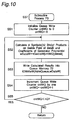
- step S51 of Fig. 10 the count value "cntWQ" of the queue write counter is initialized to 0.
- step S52 the products on the Galois field of the data d 000 calculated at step S36 and the coefficients of the generator polynomial (the Equation (14)) are read out from the Galois field operation table in the working RAM 63 by 4 symbols (32 bits). It is noted that if the count value "cntWQ" of the queue write counter is 0, then k 12 , k 11 , k 10 and k 9 are selected as the coefficients of the generator polynomial (the Equation (14)).
- step S53 the data of the products on the Galois field read out at step S52 are written into the queue memory 72.
- the 32-bit latch 75 outputs data of 00000000H
- the 8-bit latch 68 outputs data of 00H
- the input data to the EOR computing units 64, 65, 66 and 67 are data (00H, 00H, 00H, 00H) and data (k 12 ⁇ d 000 , k 11 ⁇ d 000 , k 10 ⁇ d 000 , k 9 ⁇ d 000 ).
- this data value can be expressed by the Equation (19) in a manner similar to that of the first preferred embodiment. This corresponds to step S1004 in Table 4.
- step S52 the products on the Galois field of data d 000 calculated at step S36 and the coefficients of the generator polynomial (the Equation (14)) are calculated by 4 symbols (32 bits).
- the Galois field operation table is used, where if the count value "cntWQ" of the queue write counter is 1, then k 8 , k 7 , k 6 and k 5 are selected as the coefficients of the generator polynomial (the Equation (14)).
- the data of the products calculated at step S52 are written into the queue memory 72.
- the input data to the EOR computing units 64, 65, 66 and 67 are (00H, 00H, 00H, 00H) and data (k 8 ⁇ d 000 , k 7 ⁇ d 000 , k 6 ⁇ d 000 , k 5 ⁇ d 000 ). Accordingly, if the output data of the EOR computing units 64, 65, 66 and 67 are (p 004 , p 005 , p 006 , p 007 ), then this data value can be expressed by the Equation (21) in a manner similar to that of the first preferred embodiment. This corresponds to step S1005 in Table 4.
- step S54 the count value "cntWQ" of the queue write counter is incremented by 1. As a result, the count value "cntWQ" of the queue write counter becomes 2. Then, at step S55, if the count value "cntWQ" of the queue write counter is smaller than the number of queue writes "nQ", the program flow returns to step S52. On the other hand, if not, the subroutine process P3 is ended, followed by a return.
- step S38 of Fig. 8 the count value "cnt" of the information symbol counter is incremented by 1. As a result, the count value "cnt” of the information symbol counter becomes 1. Then, at step S39, if the count value "cnt" of the information symbol counter is smaller than the number of information symbols nInfo, the program flow returns to step S32. On the other hand, if not, the subroutine process P1 is ended, followed by a return. In this case, since the count value "cnt" of the information symbol counter is 1 and the number of information symbols nInfo is 20, the program flow returns to step S32.
- an information symbol "BufB [cnt]" of the cnt-th count value of the information symbol counter is read out from the code word buffer.
- the read information symbol is the second symbol from the head symbol of the code word buffer.
- the second information symbol read out here is referred to as data of i 001 .
- 32-bit data is read out from the 32-bit latch 73, and byte data of the index-th (fourth in this operation example) byte from the most significant byte, i.e., the less significant 8-bit data are obtained.
- step S1007 the data of the 32-bit latch 73 are data (p 008 , p 009 , p 010 , p 011 ).
- step S34 the contents of the 32-bit latch 69 are cleared. This corresponds to step S1008 in Table 4.
- step S35 the contents of the queue memory 72 are advanced by the number of feeds "nFeed" of the queue memory 72.
- nothing is executed in the subroutine process P2.
- step S36 an EOR value between the input data "inDataB", and the data of the less significant 8 bits of the 32-bit latch 73 obtained at step S33 is computed, where the value of data of computing result is referred to as d 001 .
- the data value is an EOR of input data i 001 and data p 011
- the data of computing result d 001 can be expressed by the Equation (16), in a manner similar to that of the first preferred embodiment.
- step S37 the subroutine process P3, in which the products of the data value calculated at step S36 and the coefficients of the generator polynomial are written into the queue memory 72 is executed.
- the count value "cntWQ" of the queue write counter is initialized to 0.
- the products on the Galois field of the data d 001 calculated at step S36 and the coefficients of the generator polynomial (the Equation (14)) are calculated by 4 symbols (32 bits).
- the Galois field operation table is used, where if the count value "cntWQ" of the queue write counter is 0, then k 12 , k 11 , k 10 and k 9 are selected as the coefficients of the generator polynomial (the Equation (14)).
- step S54 the count value "cntWQ" of the queue write counter is incremented by 1. As a result, the count value "cntWQ” of the queue write counter becomes 1. Then, at step S55, if the count value "cntWQ" of the queue write counter is smaller than the number of queue writes "nQ", the program flow returns to step S52. On the other hand, if not, the subroutine process P3 is ended, followed by a return. In this case, since the count value "cntWQ" of the queue write counter is 1 and the number of queue writes "nQ" is 3, the program flow returns to step S52.
- step S52 the products on the Galois field of data d 001 calculated at step S36 and the coefficients of the generator polynomial (the Equation (14)) are calculated by 4 symbols (32 bits).
- the Galois field operation table is used, where if the count value "cntWQ" of the queue write counter is 1, then k 8 , k 7 , k 6 and k 5 are selected as the coefficients of the generator polynomial (the Equation (14)).
- step S53 data of the results calculated at step S52 are written into the queue memory 72.
- the input data to the EOR computing units 64, 65, 66 and 67 are data (p 003 , p 004 , p 005 , p 006 ) and data (k 8 ⁇ d 001 , k 7 ⁇ d 001 , k 6 ⁇ d 001 , k 5 ⁇ d 001 ).
- step S54 the count value "cntWQ" of the queue write counter is incremented by 1. As a result, the count value "cntWQ" of the queue write counter becomes 2. Then, at step S55, if the count value "cntWQ" of the queue write counter is smaller than the number of queue writes "nQ", the program flow returns to step S52. On the other hand, if not, the subroutine process P3 is ended, followed by a return. In this case, since the count value "cntWQ" of the queue write counter is 2 and the number of queue writes "nQ" is 3, the program flow returns to step S52.
- an information symbol "BufB [cnt]" of the cnt-th count value of the information symbol counter is read out from the code word buffer.
- the read information symbol is the third symbol from the head symbol of the code word buffer.
- the third information symbol from the head symbol taken out here is referred to as i 002 .
- 32-bit data is read out from the 32-bit latch 73, and byte data of the index-th (fourth in this operation example) byte from the most significant byte, i.e., the less significant 8 bits are obtained.
- the contents of the 32-bit latch 73 are data (p 020 , p 021 , p 022 , p 023 ), the less significant 8-bit data is p 023 .
- step S34 the contents of the 32-bit latch 69, which is the output port, are cleared.
- step S35 the contents of the queue memory 72 are advanced by the number of feeds "nFeed" of the queue memory 72, where in this operation example, nothing is executed in the subroutine process P2 in a manner similar to that of the above-mentioned processes.
- step S22 of Fig. 7 32-bit data that have overflowed from the queue memory 72 are read out as dummy data. This corresponds to step S1102 in Table 4.
- step S23 the contents of the queue memory 72 are advanced by the number of feeds "nFeed" of the queue memory 72.
- step S24 parity symbols are read out from the queue memory 72 in a unit of 4 symbols, to "nParity" symbols in total, and then are stored in the parity word region of the code word buffer BufB []. This process is referred to as a subroutine process P4.
- step S61 the count value "cntRQ" of the queue read counter is initialized to 0.
- step S62 parity symbols are read out from the queue memory 72 in a unit of 4 symbols.
- step S63 parity symbols corresponding to the 4 symbols (32 bits) taken out at step S62 are stored in the parity word region of the code word buffer.
- the number of information symbols "nInfo” is 20 and the count value "cntRQ” of the queue read counter is 0, a position BufB [nInfo+cntRQ ⁇ 4, ...
- step S64 the count value "cntRQ" of the queue read counter is incremented by 1. In this case, the count value "cntRQ” becomes 1. Then, at step S65, if the count value "cntRQ" of the queue read counter is smaller than the number of queue writes "nQ", the program flow returns to step S62. On the other hand, if not, the subroutine process P4 is ended, followed by a return. In this case, since the count value "cntRQ" is 1 and the number of queue writes "nQ" is 3, the program flow returns to step S62.
- step S64 the count value "cntRQ" of the queue read counter is incremented by 1. In this case, the count value "cntRQ” becomes 2. Further, at step S65, if the count value "cntRQ" of the queue read counter is smaller than the number of queue writes "nQ", the program flow returns to step S62. On the other hand, if not, the subroutine process P4 is ended, followed by a return. In this case, since the count value "cntRQ" is 2 and the number of writes "nQ" is 3, the program flow returns to step S62. Then, the processes of steps S62, S63 and S64 are iterated likewise, followed by going to step S65.
- the subroutine process P4 is ended, followed by a return to the original main routine.
- the subroutine process P4 corresponds to the processes of steps S1103, S1104 and S1105 in Table 4.
- Table 5 shows the statuses of the individual 32-bit latches of Fig. 5 in this operation example when the device for error correcting coding operates according to the flow charts of Figs. 5 to 11.
- double underlines represent data write
- underlines represent data read.
- the notation of parity symbols having data p 000 at their heads and symbols having data d 000 at their heads are values to be calculated by the calculation method as shown in Fig. 14, unlike the symbols in the first preferred embodiment and the first operation example of this preferred embodiment.
- the number of information symbols "nInfo" is 10 and the number of parity symbols "nParity" is 5.
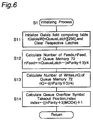
- step S12 the number of feeds "nFeed” of the queue memory 72 represented by the Equation (31) is calculated.
- the number “nQueueLatch” of 32-bit latches constituting the queue memory 72 is 3 and the number “nParity” of parity symbols to be added is 5, the number of feeds "nFeed” of the queue memory 72 becomes 1.
- the number of writes "nQ" of the queue memory 72 represented by the Equation (32) is calculated. In this operation example, since the number "nParity" of parity symbols to be added is 5, the number of writes "nQ" of the queue memory 72 becomes 2.
- a queue overflow symbol takeout position "index” represented by the Equation (33) is calculated.
- the queue overflow symbol takeout position "index” becomes 1.
- the count value "cnt" of the information symbol counter is initialized to 0. Then, at step S32, an information symbol "BufB [cnt]" of the information-symbol-counter count value cnt-th information symbol “BufB [cnt]” is read out from the code word buffer. In this case, since the count value "cnt" of the information symbol counter is 0, the read information symbol is the leading head symbol of the code word buffer. Hereinafter, the head information symbol read out here is referred to as data i 000 .
- step S33 32-bit data is read out from the 32-bit latch 73, and byte data of the index-th (first in this operation example) byte as counted from the most significant byte, i.e., the more significant 8 bits are obtained.
- the data of the more significant 8 bits is the data of 00H.
- step S2002 the contents of the 32-bit latch 73 are cleared to 0.
- step S2003 the contents of the 32-bit latch 69 are cleared to 0.
- step S35 a subroutine process P2 in which the contents of the queue memory 72 are advanced to the number of feeds "nFeed" of the queue memory 72 is executed.
- step S41 the count value "cntFeed" of the feed counter of the queue memory 72 is initialized to a number of feeds "nFeed" of the queue memory 72.
- the count value "cntFeed” is 1.
- step S42 if the count value "cntFeed" of the feed counter of the queue memory 72 is larger than 0, the program flow goes to step S43.
- step S43 if not, the subroutine process P2 is ended, followed by a return.
- step S43 the program flow goes to step S43.
- step S44 the count value "cntFeed" of the feed counter of the queue memory 72 is decremented by 1. In this case, the count value "cntFeed” becomes 0.
- step S42 if the count value "cntFeed” of the feed counter of the queue memory 72 is larger than 0, the program flow goes to step S43.
- step S42 if not, the subroutine process P2 is ended, followed by a return. In this case, since the count value "cntFeed" is 0, the subroutine process P2 is ended, followed by a return to the subroutine process P1 of Fig. 8.
- an EOR value between the input data and the data of the more significant 8 bits of the 32-bit latch 73 obtained at step S33 is calculated, where the resulting data value is referred to as d 000 .
- step S37 a subroutine process P3 in which the products of the data value calculated at step S36 and the coefficients of the generator polynomial are written into the queue memory 72 is executed.
- this subroutine process P3 will be described concretely with reference to Fig. 10.
- the input data to the EOR computing units 64, 65, 66 and 67 are data (00H, 00H, 00H, 00H) and data (k 5 ⁇ d 000 , k 4 ⁇ d 000 , k 3 ⁇ d 000 , k 2 ⁇ d 000 ).
- step S54 the count value "cntWQ" of the queue write counter is incremented by 1. As a result, the count value "cntWQ” of the queue write counter becomes 1. Then, at step S55, if the count value "cntWQ" of the queue write counter is smaller than the number of queue writes "nQ", the program flow returns to step S52. On the other hand, if not, the subroutine process P3 is ended, followed by a return. In this case, since the count value "cntWQ" of the queue write counter is 1 and the number of queue writes "nQ" is 2, the program flow returns to step S52.
- step S52 products on the Galois field of data d 000 calculated at step S36 and the coefficients of the generator polynomial (the Equation (34)) are calculated by 4 symbols (32 bits).
- the Galois field operation table is used, where if the count value "cntWQ" of the queue write counter is 1, then k 1 , 0, 0 and 0 are selected as the coefficients of the generator polynomial (the Equation (14)).
- step S53 data of the results calculated at step S52 are written into the queue memory 72.
- the 32-bit latch 75 outputs the data of 00000000H and the 8-bit latch 68 outputs the data of 00H;
- step S54 the count value "cntWQ" of the queue write counter is incremented by 1. As a result, the count value "cntWQ" of the queue write counter becomes 2. Then, at step S55, if the count value "cntWQ" of the queue write counter is smaller than the number of queue writes "nQ", the program flow returns to step S52. On the other hand, if not, the subroutine process P3 is ended, followed by a return. In this case, since the count value "cntWQ" of the queue write counter is 2 and the number of queue writes "nQ" is 2, the subroutine process P3 is ended, followed by a return to the subroutine process P1 of Fig. 8.
- the information-symbol-counter count value cnt-th information symbol "BufB [cnt]" is read out from the code word buffer.
- the read information symbol is the second symbol from the head symbol of the code word buffer.
- the second information symbol read out here is referred to as data i 001 .
- 32-bit data is read out from the 32-bit latch 73, and the byte data of the index-th (first in this operation example) byte from the most significant byte, i.e., the more significant 8 bits are obtained.
- step S2008 the contents of the 32-bit latch 73 are (p 004 , 00H, 00H, 00H), the more significant 8-bit data is p 004 .
- step S2007 the contents of the 32-bit latch 69 are cleared to 0.
- step S2008 the contents of the 32-bit latch 69 are cleared to 0.
- a subroutine process P2 in which the contents of the queue memory 72 are advanced by the number of feeds "nFeed" of the queue memory 72 is executed.
- the queue memory 72 is advanced only once. This corresponds to step S2009 in Table 5.
- step S36 of Fig. 8 an EOR value between the input data and the data of the more significant 8 bits of the 32-bit latch 73 obtained at step S33 is calculated, where the resulting data value is referred to as d 001 .
- step S37 the subroutine process P3, in which products of the data value calculated at step S36 and the coefficients of the generator polynomial are written into the queue memory 72, is executed.
- this subroutine process P3 will be described concretely with reference to Fig. 10.
- the count value "cntWQ" of the queue write counter is initialized to 0.
- the products on the Galois field of the data d 001 calculated at step S36 and the coefficients of the generator polynomial (the Equation (34)) are calculated by 4 symbols (32 bits).
- the Galois field operation table is used, where if the count value "cntWQ" of the queue write counter is 0, then k 5 , k 4 , k 3 and k 2 are selected as the coefficients of the generator polynomial (the Equation (34)).
- data of results calculated at step S52 are written into the queue memory 72.
- the input data to the EOR computing units 64, 65, 66 and 67 are data (00H, p 000 , p 001 , p 002 ) and data (k 5 ⁇ d 001 , k 4 ⁇ d 001 , k 3 ⁇ d 001 , k 2 ⁇ d 001 ).
- step S2010 in Table 5 This corresponds to step S2010 in Table 5.
- step S54 the count value "cntWQ" of the queue write counter is incremented by 1. As a result, the count value "cntWQ” of the queue write counter becomes 1. Then, at step S55, if the count value "cntWQ" of the queue write counter is smaller than the number of queue writes "nQ", the program flow returns to step S52. On the other hand, if not, the subroutine process P3 is ended. In this case, since the count value "cntWQ" of the queue write counter is 1 and the number of queue writes "nQ" is 2, the program flow returns to step S52.
- step S52 products on the Galois field of data d 001 calculated at step S56 and the coefficients of the generator polynomial (the Equation (34)) are calculated by 4 symbols (32 bits).
- the Galois field operation table is used, where if the count value "cntWQ" of the queue write counter is 1, then k 1 , 0, 0 and 0 are selected as the coefficients of the generator polynomial (the Equation (14)).
- step S53 data of the results calculated at step S52 are written into the queue memory 72.
- the input data to the EOR computing units 64, 65, 66 and 67 are data (p 003 , p 004 , 00H, 00H) and data (k 1 ⁇ d 001 , 00H, 00H, 00H).
- step S2011 in Table 5 This corresponds to step S2011 in Table 5.
- step S54 of Fig. 10 the count value "cntWQ" of the queue write counter is incremented by 1. As a result, the count value "cntWQ” of the queue write counter becomes 2. Then, at step S55, if the count value "cntWQ" of the queue write counter is smaller than the number of queue writes "nQ", the program flow returns to step S52. On the other hand, if not, the subroutine process P3 is ended, followed by a return. In this case, since the count value "cntWQ" of the queue write counter is 2 and the number of queue writes "nQ" is 2, the subroutine process P3 is ended, followed by a return to the subroutine process P1 of Fig. 8.
- step S38 of Fig. 8 the count value "cnt" of the information symbol counter is incremented by 1. As a result, the count value "cnt” of the information symbol counter becomes 2. Then, at step S39, if the count value "cnt" of the information symbol counter is smaller than the number of information symbols "nInfo", the program flow returns to step S32. On the other hand, if not, the subroutine process P1 is ended, followed by a return. In this case, since the count value "cnt" of the information symbol counter is 2 and the number of information symbols "nInfo" is 10, the program flow returns to step S32.
- the information-symbol-counter count value cnt-th information symbol "BufB [cnt]" is read out from the code word buffer within the working RAM 63.
- the count value "cnt" of the information symbol counter is 2
- the read information symbol is the third symbol from the head symbol of the code word buffer.
- the third information symbol taken out here is referred to as data i 002 .
- 32-bit data is taken out from the 32-bit latch 73, and the byte data of the index-th (first in this operation example) byte from the most significant byte, i.e., more significant 8-bit data is obtained.
- step S36 of Fig. 8 an EOR value between the input data and the data of the more significant 8 bits of the 32-bit latch 73 obtained at step S33 is calculated, where the resulting data value is referred to as d 002 .
- the data value is an EOR of input data i 002 and data p 009
- step S22 of Fig. 7 32-bit data that have overflowed from the queue memory 72 are read out as dummy data. This corresponds to step S2052 in Table 5.
- step S23 a subroutine process P2 in which the contents of the queue memory 72 are advanced by the number of feeds "nFeed" of the queue memory 72 is executed.
- this subroutine process P2 in a manner similar to that of the above-mentioned process, the queue memory 72 is advanced only once. This corresponds to step S2053 in Table 5.
- a subroutine process P4 is executed in which parity symbols are read out from the queue memory 72 in a unit of 4 symbols, to "nParity" symbols in total, and stored in the parity word region of the code word buffer "BufB []" within the working RAM 63.
- the contents of the subroutine process P4 will be described concretely with reference to Fig. 11.
- the count value "cntRQ" of the queue read counter is initialized to 0.
- parity symbols are read out from the queue memory 72 in a unit of 4 symbols.
- parity symbols corresponding to the 4 symbols (32 bits) taken out at step S62 are stored in the parity word region of the code word buffer within the working RAM 63.
- the number of information symbols "nInfo” is 10 and the count value "cntRQ” of the queue read counter is 0, a position BufB [nInfo+cntRQ ⁇ 4, ...
- parity symbols are read out from the queue memory 72 in a unit of 4 symbols.
- parity symbols corresponding to the 4 symbols (32 bits) read out at step S62 are stored in the parity word region of the code word buffer within the working RAM 63.
- a position BufB [nInfo+cntRQ ⁇ 4, ... , nInfo+cntRQ ⁇ 4+3] where the parity symbols are stored to the code word buffer is BufB [14, ... , 17].
- the second preferred embodiment presented above can produce the following effects in addition to the effects as shown in the first preferred embodiment.
- the product data on the Galois field of input data and coefficients of the generator polynomial are previously computed and stored in the ROM 71, and are transferred to the working RAM 63 in the initializing process, where the working RAM 63 constitutes coefficient storage means.
- the circuit device of Figs. 3 and 4 is so arranged as to be capable of reading out product data of 4 symbols at the same time from the working RAM 63 serving as coefficient storage means.
- the first storage means and the selecting means are implemented by using the queue memory 72, which comprises m-stage 32-bit latches 72-1 to 72-m
- the second storage means is implemented by using the 8-bit latch 68.
- the EOR operation means is implemented by using the 8-bit EOR computing units 64, 65, 66 and 67, and the read control means and the first and second selecting means are implemented by using the CPU 61 and the latch control circuit 62 that execute the programs stored in the ROM 71.
- Fig. 15 is a block diagram showing an arrangement of a device for error correcting decoding of a third preferred embodiment according to the present invention.
- the device for error correcting decoding of this third preferred embodiment comprises:
- reception polynomial Y(X) A(X) + E(X)
- the remainder polynomial r(X) which is the remainder of dividing the reception polynomial Y(X) by the generator polynomial G(X)
- the parity polynomial R(X) that is the remainder of dividing the information polynomial I(X) by the generator polynomial G(X). That is, upon inputting the received word Y to the device for error correcting coding, a remainder vector r in place of a parity word is obtained as the remainder of dividing the inputted received word Y by the generator polynomial G(X).
- the device for error correcting coding of the second preferred embodiment can be employed as the remainder computing unit 208.
- the data of error numerical values are outputted to the second input terminal of the EOR computing unit 211, while the data of error positions are outputted, as addresses, to the read controller 210 for received word storage unit and the write controller 212 for received word storage unit.
- any error is corrected by adding an error numerical value e jn to the received symbol y jn located at the error position j n .
- the following processes are carried out. First of all, an error position j n is inputted, as an address, to the read controller 210 for received word storage unit that controls the data read operation of the received word storage unit 213, and the received symbol Y jn located at the error position j n is read out from the received word storage unit 213.
- the read received symbol Y jn as well as an error numerical value e jn corresponding thereto, are inputted to the EOR computing unit 211, by which the sum (y jn + e jn ) of the received symbol y jn and the error numerical value e jn is obtained as output data. Since this output data (y jn + e jn ) becomes a corrected code symbol a jn , this corrected code symbol a jn is written into the received word storage unit 213 with handling the origin error position j n as the address and by using the write controller 212 for received word storage unit that controls the data write operation of the received word storage unit 213.
- an error-corrected code word A can be obtained at the received word storage unit 213.
- the code word A is read out by the read controller 210 for received word storage unit and outputted as error-corrected output data.
- a device for error correcting decoding can be implemented by using the device for error correcting coding of the second preferred embodiment. Therefore, in a manner similar to that of the first and second preferred embodiments, there can be provided a device for error correcting decoding which is simple in circuit configuration, as compared with the prior art device, and which has a decoding rate sufficient for practical use and is capable of decoding error correcting codes having various minimum inter-code distances without changing the circuit configuration.
- the device for error correcting coding may be constituted as follows. That is, the device for error correcting coding of a modification is a device for error correcting coding for encoding an error correcting code for input data of natural number N bits per symbol, by using a Reed-Solomon code having elements on a Galois field GF(2 N ) having a number of elements of 2 N , wherein said device comprises:
- the ROM 14 is employed to store product data.
- the present invention is not limited to this, and the ROM 14 may be substituted by computing means which is implemented by a logic circuit made of a combination of logic circuit elements, and which computes product data for input data.
- computations for the encoding process are accomplished with an arrangement that the EOR computing units (15 - 18) are enabled to read out 4 pieces of product data, as one set, in parallel (simultaneously) from the ROM 14 that has stored a plurality of product data, and by simultaneously processing with the four product data and by selectively and iteratively using the three 32-bit latches (20 - 22) in succession.
- the circuit configuration can be greatly simplified, as compared with the circuit configuration of the prior art device for error correcting coding of Fig. 14, while computations can be accomplished efficiently and with a high speed so that error correcting codes can be encoded at such a coding rate that the device can be put into practical use.
- a device for error correcting decoding implemented by using the device for error correcting coding according to the present invention can be greatly simplified in circuit configuration while computations can be performed efficiently and with a high speed, so that error correcting codes can be decoded at such a decoding rate that the device can be put into practical use.
Abstract
Description
- The present invention relates to device and method for error correcting coding, as well as device and method for error correcting decoding. In particular, the invention relates to device and method for error correcting coding for encoding error correcting codes for correcting errors in digital data during the recording or reproduction, or transmission or reception of digital data executed by digital recording equipment or digital communication equipment or the like, and also relates to device and method for error correcting decoding for decoding error correcting codes.
- In recent years, with the development of digital recording equipment and digital communication equipment, it has become an important issue how errors of digital data are reduced during the recording or reproduction, or transmission or reception of digital data. Thus, for correction of errors of digital data, error correcting codes are used in various types of equipments that treat digital data. The Reed-Solomon code is also one type of such error correcting codes, and is used primarily in, for example, digital recording devices such as PD drive units utilizing phase change.
- The Reed-Solomon code is a multi-element cyclic Hamming code in which the code word consists of elements of a Galois field GF(2N) whose number of elements is 2N, and in which if α is the primitive element of GF(2N), then the generator polynomial can be expressed by the following equation:

- Hereinafter, computational operations including the Equation (1) will be all executed on the Galois field GF(2N). Also, d denotes the minimum inter-code distance.
- Code words in the Reed-Solomon code are generated as follows:
- If an information word vector I is expressed as follows:


- Then, a code polynomial A(X) can be calculated from the information polynomial I(X) and the generator polynomial G(X) by using the following equation:

- However, the code obtained would not be a systematic code. Therefore, a code word is created as follows.
- First of all, the information polynomial I(X) is multiplied by Xn-k, and the result is divided by G(X). If the quotient is Q(X) and the remainder is R(X), then the following expression can be given:


- The A(X) calculated by the Equation (7) is divisible by the generator polynomial G(X), thus resulting in a code polynomial. If the code polynomial R(X) is expressed as follows:


- The code word represented by the code polynomial of the Equation (9) can be represented in vector representation as follows:


- The code generated in this way as shown above is written as a Reed-Solomon code RS (n, k,

- Fig. 12 shows an example of the device for error correcting coding according to the prior art using the Reed-Solomon code. This circuit performs the division of polynomials having coefficients of Galois field GF(2N). Referring to Fig. 12, the device for error correcting coding comprises:
- (a) 8-bit EXCLUSIVE-OR
computing units 195 to 206; - (b)
coefficient multipliers 171 to 182 having coefficients k12 to k1 on the Galois field; - (c) 8-
bit latches 183 to 194; and - (d) an initial-
value setting circuit 207 for clearing to 0 the contents of the 8-bit latches 183 to 194 upon a reset. - In this device for error correcting coding, input data is inputted to a first input terminal of the EXCLUSIVE-OR
computing unit 206. The output data from the output terminal of the EXCLUSIVE-ORcomputing unit 206 is inputted to the 8-bit latch 183 via thecoefficient multiplier 171, while the output data therefrom is inputted to the EXCLUSIVE-ORcomputing units 195 to 205 via thecoefficient multipliers 172 to 183, respectively. Further, the 8-bit latches 183 to 194 and the EXCLUSIVE-ORcomputing units 195 to 206 are arranged alternately and connected in series so that data is transferred from thelatch 183 toward thelatch 194. - Next, a case where a Reed-Solomon code RS (32, 20, d = 13) with 8 bits taken as 1 symbol is actually encoded by using the device for error correcting coding of Fig. 12.
- It is noted that the primitive polynomial m(X), the primitive element d and the generator polynomial G(X) are defined as follows:

- In addition, k1 to k12 in the Equation (14) represent coefficients to be multiplied to X11 to X0, as a result of developing the generator polynomial G(X) and arraying the terms in the descending order of X.
- When a first information symbol i000, which is first input data, is inputted to the EXCLUSIVE-OR
computing unit 206, an EXCLUSIVE-OR of the first information symbol i000 and 00H, which is the output data from the 8-bit latch 194, is computed, and then, data of the computation result is inputted to the Galoisfield coefficient multipliers 171 to 182. It is noted that "H" in 00H denotes a hexadecimal representation, which is the case also hereinafter. In this case, if the data inputted to the Galoisfield coefficient multipliers 171 to 182 is d000, then the data d000, which is the EXCLUSIVE-OR of the first information symbol i000 and the data of 00H can be expressed by the following equation:
- This corresponds to a computation which presents in column number R1 and over three rows of step S101 of Fig. 13. Next, the Galois field coefficient multipliers 171 to 182 output products on the Galois field of the input data d000 and their respective coefficients k12 to 1. These products correspond to the data which present in column numbers R13 to R2 and on the second row of step S101 of Fig. 13.
- Next, the output data from the Galois field coefficient
multipliers 171 to 182 are stored in the 8-bit latches 183 to 194, respectively. Now the data stored in therespective latches 183 to 194 are referred to as P000 to p011, respectively, these data values correspond to results of performing computations which present in column numbers R13 to R2 and over the three rows of step S101 of Fig. 13, respectively. In addition, the addition sign in Fig. 13 represents an EXCLUSIVE-OR operation, and hereinafter an operation EOR represents an EXCLUSIVE-OR operation. - Next, when a second information symbol i001, which is second input data, is inputted to the
EOR computing unit 206, an EOR of the second information symbol i001 and p011, which is output data from the 8-bit latch 194, is computed, and then, data of the computation result is inputted to the Galois field coefficientmultipliers 171 to 182. In this case, if the data inputted to the Galois field coefficientmultipliers 171 to 182 is d001, then the data d001, which is the EOR of the second information symbol i001 and the data p011 can be expressed by the following equation:
- This corresponds to a computation which presents in column number R2 and over three rows of step S101 of Fig. 13. Next, the Galois field coefficient
multipliers 171 to 182 output products on the Galois field of the input data d001 and their respective coefficients k12 to 1. These products correspond to the data which presents in column numbers R14 to R3 and on the second row of step S102 of Fig. 13. - Next, the output data from the Galois field coefficient
multipliers 171 to 182 are stored in the 8-bit latches 183 to 194, respectively. Now the data stored in thelatches 183 to 194 are referred to as p012 to p023, respectively, these data values correspond to results of performing computations which present in column numbers R14 to R3 and over the three rows of step S102 of Fig. 13, respectively. - Likewise also for the following, as the information symbol i002 through information symbol i019 are inputted to the
EOR computing unit 206, computations as shown in Fig. 13 are continued, and finally, parity words (p228, p229, ..., p229), which are remainders of dividing the information words (i000, i001, ..., i019) by the generator polynomial (the Equation (14)), are stored in the 8-bit latches 183 to 194, respectively. Adding the finally obtained parity symbols p228, p229, ... and p239 in succession to the information symbols i000, i001, ... and i019 that have already been inputted completes a code word (i000, i001, ..., i019, p228, p229, ..., p239). - However, in the device for error correcting coding as shown in Fig. 12, because the Galois field coefficient
multipliers 171 to 182 have complex circuits, respectively, a large-scale circuit would be involved in encoding symbols of a long minimum inter-code distance. Also, for the device for error correcting coding as shown in Fig. 12, it would be difficult to change the minimum inter-code distance without changing the arrangement of the device. In order to change the minimum inter-code distance without changing the arrangement of the device, it is necessary to make the coefficients of the Galois field coefficient multipliers changeable without changing the arrangement of the device and to provide a circuit configuration that allows the loop of division circuits to be changed without changing the arrangement of the device. The implementation of these needs would result in further complex circuits. - A first object of the present invention is to provide device and method for error correcting coding which solve the above-mentioned problems, and which can be implemented with small-scale circuitry, as compared with that of the prior art, while fulfilling a practicable coding rate, and further which allow the minimum inter-code distance d to be freely changed without changing the arrangement of the device.
- A second object of the present invention is to provide device and method for error correcting decoding which can be implemented with small-scale circuitry, as compared with the prior art, while fulfilling a practicable decoding rate, and further which allow the minimum intercode distance d to be freely changed without changing the arrangement of the device.
- According to the present invention, there is provided a device for error correcting coding for encoding an error correcting code for input data of natural number N bits per symbol, by using a Reed-Solomon code having elements on a Galois field GF(2N) having a number of elements of 2N, said device comprising:
- product data storage means for previously storing a plurality of product data on the Galois field between each of the input data and each of coefficients of a generator polynomial of the Reed-Solomon code, with handling a plurality of b product data as one set for each address, after previously computing the plurality of product data;
- first storage means comprising a natural number of m storage units each having a storage capacity of N × b bits;
- read control means for controlling said product data storage means to read out the plurality of product data stored in said product data storage means in parallel by handling a plurality of b product data as one set, in response to the input data;
- exclusive OR operation means having first and second input terminals each of N × b bits, the plurality of b product data read out in parallel from said product data storage means by said read control means being inputted to the first input terminal, said exclusive OR operation means computing exclusive OR data between data inputted to the first input terminal and data inputted to the second input terminal, and outputting resulting computation data;
- first selecting means for controlling said first storage means to selectively and sequentially read out and output data stored in said m storage units every one storage unit thereof, to output data of more significant N × (b-1) bits out of the selectively read out and outputted data of N × b bits, to less significant N × (b-1) bits of the second input terminal of said exclusive OR operation means, and to write the resulting computation data outputted from said exclusive OR operation means into one of said m storage units by selectively and sequentially switching said m storage units; and
- second storage means having a storage capacity of N bits, for temporarily storing data of the less significant N bits out of the N × b bit data selectively outputted from one of said m storage units by said first selecting means, and for outputting temporarily stored data to the more significant N bits of the second input terminal of said exclusive OR operation means,
wherein when sequentially inputting the input data into said product data storage means, said m storage unit of said first storage means generates parity data,
wherein said device further comprises:- second selecting means for sequentially outputting the respective parity data generated by said m storage units by selectively and sequentially switching the m storage units every one storage unit in succession to the input data.
- Further, in the above-mentioned device for error correcting coding, said read control means, said first selecting means and said second selecting means are preferably implemented by a central processing unit for executing a predetermined program stored in a further storage unit.
- Further, according to the present invention, there is provided a device for error correcting decoding for decoding an error correcting code for input data of natural number N bits per symbol, by using a Reed-Solomon code having elements on a Galois field GF(2N) having a number of elements of 2N, said device comprising:
- received word storage means for storing an input received word comprised of a plurality of received symbols including input data and parity data associated with the input data, in a unit of the received symbols;
- remainder computing means comprising said device for error correcting coding as claimed in
Claim 1, said remainder computing means computing and outputting a remainder for the input received word by using a generator polynomial of the Reed Solomon code; - error numerical value and error position computing means for computing and outputting a set of an error position in the received word and an error numerical value corresponding to the error position, based on the remainder outputted from said remainder computing means;
- control means for reading out from said received word storage means and outputting a received symbol in the error position stored in said received word storage means based on the error position in the received word outputted from said error numerical value and error position computing means;
- exclusive OR operation means for computing exclusive OR data between the received symbol in the error position outputted from said read control means and the error numerical value corresponding to the error position outputted from said error numerical value and error position computing means, and outputting resulting computation data; and
- write control means for writing the resulting computation data outputted from said exclusive OR operation means into the error position in said received word storage means, and for correcting the received symbol in the error position.
- Furthermore, according to the present invention, there is provided a method for error correcting coding for encoding an error correcting code for input data of natural number N bits per symbol, by using a Reed-Solomon code having elements on a Galois field GF(2N) having a number of elements of 2N, said method including the following steps of:
- previously storing in product data storage means a plurality of product data on the Galois field between each of the input data and each of coefficients of a generator polynomial of the Reed-Solomon code, with handling a plurality of b product data as one set for each address, after previously computing the plurality of product data;
- controlling said product data storage means to read out the plurality of product data stored in said product data storage means in parallel by handling a plurality of b product data as one set, in response to the input data;
- by using exclusive OR operation means having first and second input terminals each of N × b bits, the plurality of b product data read out in parallel from said product data storage means by said read control means being inputted to the first input terminal, computing exclusive OR data between data inputted to the first input terminal and data inputted to the second input terminal, and outputting resulting computation data;
- controlling said first storage means comprising m storage unit each having a storage capacity of N x b bits, to selectively and sequentially read out and output data stored in said m storage units every one storage unit thereof, to output data of more significant N × (b-1) bits out of the selectively read out and outputted data of N × b bits, to less significant N × (b-1) bits of the second input terminal of said exclusive OR operation means, and to write the resulting computation data outputted from said exclusive OR operation means into one of said m storage units by selectively and sequentially switching said m storage units;
- by using second storage means having a storage capacity of N bits, temporarily storing data of the less significant N bits out of the N × b bit data selectively outputted from one of said m storage units, and outputting temporarily stored data to the more significant N bits of the second input terminal of said exclusive OR operation means;
- when sequentially inputting the input data into said product data storage means, generating parity data in said m storage unit of said first storage means; and
- sequentially outputting the respective parity data generated by said m storage units by selectively and sequentially switching the m storage units every one storage unit in succession to the input data.
- Still further, according to the present invention, there is provided a method for error correcting decoding for decoding an error correcting code for input data of natural number N bits per symbol, by using a Reed-Solomon code having elements on a Galois field GF(2N) having a number of elements of 2N, said method including the following steps of:
- storing in received word storage means an input received word comprised of a plurality of received symbols including input data and parity data associated with the input data, in a unit of the received symbols;
- by said method for error correcting coding as claimed in
Claim 4, computing and outputting a remainder for the input received word by using a generator polynomial of the Reed Solomon code; - computing and outputting a set of an error position in the received word and an error numerical value corresponding to the error position, based on the outputted remainder;
- reading out from said received word storage means and outputting a received symbol in the error position stored in said received word storage means based on the error position in the outputted received word;
- computing exclusive OR data between the received symbol in the outputted error position and the error numerical value corresponding to the outputted error position, and outputting resulting computation data; and
- writing the outputted resulting computation data into the error position in said received word storage means, and correcting the received symbol in the error position.
-
- Fig. 1 is a block diagram of a device for error correcting coding of a first preferred embodiment according to the present invention;
- Fig. 2 is a timing chart showing an operation of the device for error correcting coding of Fig. 1;
- Fig. 3 is a block diagram of a device for error correcting coding according to a second preferred embodiment of the present invention;
- Fig. 4 is a block diagram where m = 3 in the device for error correcting coding of Fig. 4;
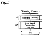
- Fig. 5 is a flow chart showing an encoding process performed by a
CPU 61 of the device for error correcting coding of Fig. 3; - Fig. 6 is a flow chart showing an initializing process (step S1), which is a subroutine of Fig. 5;
- Fig. 7 is a flow chart showing a code word generating process (step S2), which is a subroutine of Fig. 5;
- Fig. 8 is a flow chart showing a subroutine process P1 (step S7) of Fig. 7;
- Fig. 9 is a flow chart showing a subroutine process P2 (steps S23 and S35) of Figs. 7 and 8;
- Fig. 10 is a flow chart showing a subroutine process P3 (step S37) of Fig. 8;
- Fig. 11 is a flow chart showing a subroutine process P4 (step S24) of Fig. 7;
- Fig. 12 is a block diagram of a device for error correcting coding according to the prior art;
- Fig. 13 is a chart for explaining the way of calculating a Reed-Solomon code RS (n, n - 12, d = 13) in the device for error correcting coding of Fig. 12;
- Fig. 14 is a chart for explaining the way of calculating a Reed-Solomon code RS (n, n - 5, d = 6) in the device for error correcting coding of Fig. 12; and
- Fig. 15 is a block diagram of a device for error correcting decoding of a third preferred embodiment according to the present invention.
- Preferred embodiments of the present invention will be described hereinbelow with reference to the accompanying drawings.
- A first preferred embodiment according to the present invention will be described with reference to the accompanying drawings. The first preferred embodiment will be described on a case where a Reed-Solomon code RS (32, 20, d = 13) with 8 bits taken as 1 symbol is encoded. It is noted that the primitive polynomial m(X), the primitive element α and the generator polynomial G(X) are defined as shown by the Equation (12), the Equation (13) and the Equation (14), respectively.
- Fig. 1 is a block diagram showing an arrangement of a device for error correcting coding of the first preferred embodiment according to the present invention. The device for error correcting coding of this first preferred embodiment comprises:
- (a) 8-bit latches 12 and 27;
- (b) a
quaternary counter 13; - (c) a ROM (Read-Only Memory) 14;
- (d) 8-bit
EOR computing units - (e) 32-
bit bus selectors - (f) a
queue memory 30 comprising 32-bit latches 20, 21 and 22; - (g) a
decoder 24 for decoding an input data "1" to output a pulse signal; - (h) a
decoder 25 for decoding an input data "2" to output a pulse signal; - (i) a
decoder 26 for decoding an input data "3" to output a pulse signal; - (j) a
decoder 28 for decoding an input data "0" to output a pulse signal; - (k) a 2-
bit latch 29; - (l) a
delay circuit 300 comprising threesymbol delay circuits 301 to 303; and - (m) an 8-bit
output data selector 310. - In the device for error correcting coding of Fig. 1, 8-bit input data is inputted to a first input terminal of the
EOR computing unit 11, while the 8-bit input data is outputted via the d-contact of theoutput data selector 310 as output data. The output data from the output terminal of theEOR computing unit 18 is inputted to a second input terminal of theEOR computing unit 11. On the other hand, a clock CLK is inputted to both thequaternary counter 13 and thelatches quaternary counter 13, which counts the inputted clock CLK, is reset to 0 when the count value has reached 4, and outputs 2-bit data of the count value to an address terminal of theROM 14 via thelatch 29 as an address for the more significant 2 bits, while thequaternary counter 13 also outputs the data to both thebus selectors decoders bit latch 29 latches 2-bit data of the count value of thequaternary counter 13 at a timing of the trailing edge of the clock CLK. - When the output data from the
quaternary counter 13 represents a value of "0", thedecoder 28 outputs to the latch 27 a pulse signal having a width of a half cycle of the clock CLK with a time delay of a half cycle of the clock CLK. Also, when the output data from thequaternary counter 13 represents a value of "1", thedecoder 24 outputs to the latch 20 a pulse signal having a width of a half cycle of the clock CLK with a time delay of a half cycle of the clock CLK. Further, when the output data from thequaternary counter 13 represents a value of "2", thedecoder 25 outputs to the latch 21 a pulse signal having a width of a half cycle of the clock CLK with a time delay of a half cycle of the clock CLK. Still further, when the output data from thequaternary counter 13 represents a value of "3", thedecoder 26 outputs to the latch 22 a pulse signal having a width of a half cycle of the clock CLK with a time delay of a half cycle of the clock CLK. - The 8-
bit latch 12 latches 8-bit data derived from theEOR computing unit 11 at a timing of the leading edge of the clock CLK of the pulse signal derived from thedecoder 26, and outputs the latched data to theROM 14 as an address for the less significant 8 bits. TheROM 14 has previously stored results of multiplying input symbols in vector representation by predetermined coefficients on the Galois field in the form of vector representation. Input data is given as less significant 8 bits of the address, while the significant 2 bits of the address are used for changing coefficients. The 32-Bit output data from data terminals of theROM 14 are inputted to first input terminals of respective fourEOR computing units 15 to 18, and the 32-bit data outputted from their output terminals are inputted to input terminals of thebus selector 19. Also, the 8-bit output data outputted from theEOR computing unit 18 is inputted to a second input terminal of theEOR computing unit 11. - The 32-
bit bus selectors bit bus selectors bus selector 19 and the output terminals of thebus selector 23 come to open states, respectively. Also, the 32-bit bus selectors bus selector 19 are connected to input buses of the 32-bit latch 20 while thebus selector 23 is connected output buses of the 32-bit latch 20. Further, the 32-bit bus selectors bus selector 19 are connected to input buses of the 32-bit latch 21 while thebus selector 23 is connected to output buses of the 32-bit latch 21. Still further, the 32-bit bus selectors bus selector 19 are connected to input buses of the 32-bit latch 22 while thebus selector 23 is connected to output buses of the 32-bit latch 22. - The data of the more significant 24 bits out of 32-bit output data outputted from the
bus selector 23 are inputted to second input terminals of theEOR computing units bus selector 23 are inputted to the second input terminal of theEOR computing unit 15 via the 8-bit latch 27. The 8-bit latch 27 latches the input 8-bit data at a timing of the leading edge of the clock CLK, and then outputs the latched data to the second input terminal of theEOR computing unit 15, and further clears to 0 the latched data in response to a pulse signal derived from thedecoder 28. - The 32-Bit output data outputted from the 32-
bit latch 20 is inputted to thesymbol delay circuit 301. Then, among the inputted 32-bit data, thesymbol delay circuit 301 operates: - (a) to output, as output data, the more significant 8 bit data via the b-contact of the 8-
bit bus selector 310 without any delay in succession to the information symbols outputted from the a-contact of the bus selector 310 (the output timing of this output data being referred to as a reference output timing hereinafter); - (b) to output, as output data, the next more significant 8 bit data via the b-contact of the 8-
bit bus selector 310 after a delay of 1 symbol (= 1 byte = 8 bits) from the reference output timing; - (c) to output, as output data, the further next more significant 8 bit data via the b-contact of the 8-
bit bus selector 310 after a delay of 2 symbols from the reference output timing; and - (d) to output, as output data, the succeeding less significant 8 bit data via the b-contact of the 8-
bit bus selector 310 after a delay of 3 symbols from the reference output timing. - Also, the 32-bit output data outputted from the 32-
bit latch 21 is inputted to thesymbol delay circuit 302. Then, among the inputted 32-bit data, thesymbol delay circuit 302 operates: - (a) to output, as output data, the more significant 8 bit data via the c-contact of the 8-
bit bus selector 310 after a delay of 4 symbols from the reference output timing; - (b) to output, as output data, the next more significant 8 bit data via the c-contact of the 8-
bit bus selector 310 after a delay of 5 symbols from the reference output timing; - (c) to output, as output data, the further next more significant 8 bit data via the c-contact of the 8-
bit bus selector 310 after a delay of 6 symbols from the reference output timing; and - (d) to output, as output data, the succeeding less significant 8 bit data via the c-contact of the 8-
bit bus selector 310 after a delay of 7 symbols from the reference output timing. - Further, the 32-bit output data outputted from the 32-
bit latch 22 is inputted to thesymbol delay circuit 303. Then, among the inputted 32-bit data, thesymbol delay circuit 303 operates: - (a) to output, as output data, the more significant 8 bit data via the d-contact of the 8-
bit bus selector 310 after a delay of 8 symbols from the reference output timing; - (b) to output, as output data, the next more significant 8 bit data via the d-contact of the 8-
bit bus selector 310 after a delay of 9 symbols from the reference output timing; - (c) to output, as output data, the further next more significant 8 bit data via the d-contact of the 8-
bit bus selector 310 after a delay of 10 symbols from the reference output timing; and - (d) to output, as output data, the succeeding less significant 8 bit data via the d-contact of the 8-
bit bus selector 310 after a delay of 11 symbols from the reference output timing. - Accordingly, in succession to information symbols, for example, 20 symbols that are inputted to the device for error correcting coding, a parity word of 32 bits = 4 symbols that have been encoded for error correction and stored in the
latch 20, a parity word of 32 bits = 4 symbols that have been encoded for error correction and stored in thelatch 21 and a parity word of 32 bits = 4 symbols that have been encoded for error correction and stored in thelatch 22 are outputted from thebus selector 310 as output data. - Fig. 2 is a timing chart showing an operation of the device for error correcting coding of Fig. 1. Input data of 8 bits is inputted once every four pulses of the clock CLK. The
quaternary counter 13 is set to an initial value of 2, the 8-bit latches 12 and 27 and the 32-bit latches 20, 21 and 22 are set to an initial value of 0, and the 2-bit latch 29 is set to an initial value of 0. - Table 1 and 2 show the contents of data to be stored in the
ROM 14. Referring to Tables 1 and 2, k1 to k12 denote coefficients of the generator polynomial G(X) shown in the Equation (14), α is the primitive element of Galois field GF(28), and the product sign represents a product on the Galois field. km, αn (where m is an natural number of 1 to 12 and n is an integer equal to or larger than 0) are elements of the Galois field GF(28) Therefore, products of km and αn are also elements of the Galois field GF(28) and, since their vector representations correspond to 8-bit numerical values, respectively, the numerical value data of the products are previously stored in theROM 14. - In Tables 1 and 2, an address H is an address of the more significant 2 bits of the
ROM 14, and an address L is an address of the less significant 8 bits of theROM 14. Also, b[31, ..., 24] is coefficient data of the more significant 8 bits, b[23, ..., 16] is coefficient data of the next more significant 8 bits, b[15, ..., 8] is coefficient data of the further next more significant 8 bits and b[7, ..., 0] is coefficient data of the less significant 8 bits. - Table 3 is a transformation table for transforming the elements on the Galois field GF(28) from vector representation into those in power representation. Table 3 is presented for reference's sake, and is not any data which is used directly in the present preferred embodiment. As apparent from Table 3, it can be seen that, when data values of the address L of the
ROM 14 as shown in Tables 1 and 2 are transformed into those in the power representation, those correspond to the term αn (where n is an integer equal to or larger than zero) in the values written in the address. Accordingly, it can be understood that, for example, if 0 is inputted as the address H and the element of the Galois field GF(28) in vector representation (8 bits) is inputted to the address L in theROM 14, then theROM 14 outputs the product on the Galois field of the coefficients k12, k11, k10 and k9 of the generator polynomial and the value inputted to the address L.Table 1 Address H Address L b[31, ..., 24] b[23, ...,16] b[15, ..., 8] b[7, ..., 0] 0 00H 0 0 0 0 0 01H k12 k11 k10 k9 0 02H k12·α k11·α k10·α k9· α 0 03H k12·α25 k11·α25 k10·α25 k9· α 250 04H k12·α2 k11·α2 k10·α2 k9· α 20 05H k12·α50 k11·α50 k10·α50 k9· α 50... ... ... ... ... ... 0 FBH k12·α234 k11·α234 k10·α234 k9· α 2340 FCH k12·α168 k11·α168 k10·α168 k9· α 1680 FDH k12·α80 k11·α80 k10·α80 k9· α 800 FEH k12·α88 k11·α88 k10·α88 k9· α 880 FFH k12·α175 k11·α175 k10·α175 k9· α 1751 00H 0 0 0 0 1 01H k8 k7 k6 k5 1 02H k8·α k7·α k6·α k5· α 1 03H k8·α25 k7·α25 k6·α25 k5· α 251 04H k8·α2 k7·α2 k6·α2 k5· α 21 05H k8·α50 k7·α50 k6·α50 k5· α 50... ... ... ... ... ... 1 FBH k8·α234 k7·α234 k6·α234 k5· α 2341 FCH k8·α168 k7·α168 k6·α168 k5· α 1681 FDH k8·α80 k7·α80 k6·α80 k5· α 801 FEH k8·α88 k7·α88 k6·α88 k5· α 881 FFH k8·α175 k7·α175 k6·α175 k5·α175 Table 2 Address H Address L b[31, ..., 24] b[23, ..., 16] b[15, ..., 8] b[7, ..., 0] 2 00H 0 0 0 0 2 01H k4 k3 k2 k1 2 02H k4·α k3·α k2·α k1· α 2 03H k4·α25 k3·α25 k2·α25 k1· α 252 04H k4·α2 k3·α2 k2·α2 k1· α 22 05H k4·α50 k3·α50 k2·α50 k1· α 50... ... ... ... ... ... 2 FBH k4·α234 k3·α234 k2·α234 k1· α 2342 FCH k4·α168 k3·α168 k2·α168 k1· α 1682 FDH k4·α80 k3·α80 k2·α80 k1· α 802 FEH k4·α88 k3·α88 k2·α88 k1· α 882 FFH k4·α175 k3·α175 k2·α175 k1· α 1753 00H 0 0 0 0 3 01H 0 0 0 0 3 02H 0 0 0 0 3 03H 0 0 0 0 3 04H 0 0 0 0 3 05H 0 0 0 0 ... ... ... ... ... ... 3 FBH 0 0 0 0 3 FCH 0 0 0 0 3 FDH 0 0 0 0 3 FEH 0 0 0 0 3 FFH 0 0 0 0 Table 3 Vector representation Power representation 00000000 X 00000001 α0 00000010 α1 00000011 α25 00000100 α2 00000101 α50 00000110 α26 00000111 α198 ... ... 11111010 α244 11111011 α234 11111100 α168 11111101 α80 11111110 α88 11111111 α175 - Hereinbelow, the error correction encoding process in the device for error correcting coding of Fig. 1 will be described with reference to Fig. 2.
- First of all, at the leading edge of an output pulse signal of the
decoder 26 that synchronizes with the trailing edge of the first clock CLK, the 32-bit bus selectors bit latch 22. At this time, since the input data of the 8-bitEOR computing unit 18 are the data of 00H, which is the less significant 8 bits of the output data from theROM 14, and the data of 00H corresponding to the 16th to 9th bits of the output data from the 32-bit latch 22, the output data from the 8-bitEOR computing unit 18 is 00H. Therefore, input data to the 8-bitEOR computing unit 11 are the data of 00H, which is the output data from the 8-bitEOR computing unit 11, and inputted data i000, so that the data i000 is stored in the 8-bit latch 12. Thus, the data d000 of Fig. 2 can be expressed by the Equation (15). At the same time, the 8-bitEOR computing unit 15 outputs an EOR data between output data from the 8-bit latch 27 and the more significant 8 bits of output data from theROM 14, while the 8-bitEOR computing units bit latch 22 and the less significant 24 bits of output data from theROM 14. Accordingly, the output data from these four 8-bitEOR computing units bit latch 22. Also, simultaneously with this time, the less significant 8 bits of the data that have previously been written in the 32-bit latch 22 is written into the 8-bit latch 27. In this case, since the 8-bit input data to the 8-bitEOR computing units bit latch 22 is 00000000H. The data written into the 8-bit latch 27 is 00H. After these operations, the less significant 8 bits of the address given to theROM 14 become d000, and its more significant 2 bits become "3". At this time, such data as shown in Table 1 has been stored in theROM 14, so that the computation of products on the Galois field can be obtained with reference to table. In this case, since the more significant 2 bits of the address is "3", theROM 14 outputs the data of 00000000H from its data terminal. Therefore, the output data A0 from theROM 14 of Fig. 2, if grouped in a unit of 8 bits, can be represented by the following equation:
- Next, at the leading edge of the output pulse signal of the
decoder 28 that synchronizes with the trailing edge of the second clock CLK, the 8-bit latch 27 is cleared to 0. The less significant 8 bits of the address given to theROM 14 keeps unchanged as d000, while its more significant 2 bits become "0". Therefore, from Table 1, the output data A1 from theROM 14 of Fig. 2 can be expressed by the following equation:
- Next, at the leading edge of an output signal from the
decoder 24 that synchronizes with the trailing edge of the third clock CLK, the 32-bit bus selectors bit latch 20. At this time, the 8-bitEOR computing unit 15 outputs an EOR data between output data from the 8-bit latch 27 and the more significant 8 bits of output data from theROM 14, while the 8-bitEOR computing units bit latch 20 and the less significant 24 bits of output data from theROM 14. Accordingly, 32-bit output data from these 8-bitEOR computing units bit latch 20. Also, simultaneously with this time, the less significant 8 bits of the data that have previously been written in the 32-bit latch 20 is written into the 8-bit latch 27. In this case, since the output data from the 8-bit latch 27 is 00H and the more significant 24 bits of output data from the 32-bit latch 20 is also data of 000000H, the data written into the 32-bit latch 20 is the data A1 itself expressed by the Equation (18). Therefore, (p000, p001, p002, p003), which is the output data from the 32-bit latch 20 of Fig. 2, can be expressed by the following equation:
- Also, the data written into the 8-
bit latch 27 is data of 00H. After these operations, the less significant 8 bits of the address given to theROM 14 become d000, and its more significant 2 bits become "1". Therefore, the output data A2 from theROM 14 of Fig. 2 can be represented by the following equation:
- Likewise, data (p004, p005, p006, p007) can be expressed by the following equation:

- Also, the output data A3 from the
ROM 14 can be expressed by the following equation:
- Also, data (p008, p009, p010, p011) can be expressed by the following equation:

- However, the output data from the 8-
bit latch 12 will change in synchronization with the trailing edge of the fifth clock CLK. More specifically, since the 32-bit bus selectors bit latch 22 at the leading edge of the output pulse signal of thedecoder 26, input data to the 8-bitEOR computing unit 11 become p011, which is output data from the 8-bitEOR computing unit 18, and input data i001, in a manner similar to that of the case of the first clock CLK, so that data d001 expressed by the Equation (15) is stored in the 8-bit latch 12. In addition, the sign of addition in the Equation (15) means a computation of an addition on the Galois field. - Next described is the state at the leading edge of the output signal from the
decoder 24 that synchronizes with the trailing edge of the seventh clock CLK. At this time, the 32-bit bus selectors bit latch 20. Reasoning in a manner similar to that of the above-mentioned process, the output data from the 8-bit latch 27 is 00H and the more significant 24 bits of output data from the 32-bit latch 20 are as follows:

bit latch 20. - Also, data p003, which is the less significant 8 bits of the data value prior to the writing into the 32-
bit latch 20 is written into the 8-bit latch 27 at the same time. After these operations, the less significant 8 bits of the address given to theROM 14 become data d001, and its more significant 2 bits become "1". - Therefore, the output data B2 from the
ROM 14 of Fig. 2 can be expressed by the following equation:
- Likewise, data (p016, p017, p018, p019) can be expressed by the following equation:

- Also, the output data B3 from the
ROM 14 can be expressed by the following equation:
- Further, data (p020, p021, p022, p023) can be expressed by the following equation:

- Also, since the output data from the 8-bit
EOR computing unit 18 is p023 at the leading edge of the output signal from thedecoder 26 that synchronizes with the trailing edge of the ninth clock CLK, data d002 can be expressed by the following equation:
- Repeating the above-mentioned operations until the (4×20 + 1)-th clock CLK is inputted completes a parity word of total 12 symbols in the 32-bit latches 20 and 21 and 22. Adding the parity word of 12 symbols here generated to the information symbols of 20-symbol input data, i.e., information word, that have been inputted so far completes a code word of total 32 symbols, i.e., output symbol string. Therefore, in succession to the information word of 20 symbols, a parity word of 12 symbols are outputted, as

delay circuit 300 and theoutput data selector 310. - As described above, in the present preferred embodiment, a Reed-Solomon code RS (n, n - 12, d = 13) having a minimum inter-code distance d = 13 can be coded by the followings:
- (a) the 32-
bit ROM 14, which is means for storing product data, after computing a plurality of product data on the Galois field between individual coefficients of a generator polynomial and input information symbols in response to 8-bit input data which is an information word, theROM 14 being for storing four pieces of product data as one set with respect to each address, wherein four product data as one set can be read out therefrom by theEOR computing units 15 to 18 in parallel (simultaneously); - (b) the three 32-bit latches 20, 21 and 22, which are first storage means;
- (c) the 8-
bit latch 27, which is second storage means; - (d) the 8-bit
EOR computing units - (e) the 32-
bit bus selectors - (f) the
quaternary counter 13, thelatches decoders 24 to 26 and 28, which are read control means; and - (g) the
delay circuit 300 and theoutput data selector 310, which are second selecting means. - In the above-mentioned first preferred embodiment, the
ROM 14 that has stored a plurality of product data is configured so as to be readable for theEOR computing units 15 to 18 in such a manner that four pieces of product data can be read out as one set in parallel (simultaneously), and the operations for encoding process are achieved by simultaneously processing four pieces of product data by using the three 32-bit latches 20 to 22 selectively and repeatedly in succession. Thus, the circuit configuration can be greatly simplified, as compared with the circuit configuration of the prior art device for error correcting coding of Fig. 14. Besides, the computations can be executed with a high efficiency and with a high speed, so that error correcting codes can be encoded at such a coding rate that the device can be put into practical use enough. - In the first preferred embodiment, if the number of 32-bit latches 20, 21 and 22 constituting the first storage means is increased so as to be the number equal to or greater than three and if the contents stored in the
ROM 14 are changed so as to correspond thereto, then it becomes possible to encode any error correcting code having an even longer minimum inter-code distance d by using a similar circuit without changing the circuit configuration. - Fig. 3 is a block diagram of a device for error correcting coding according to a second preferred embodiment of the present invention. Referring to Fig. 3, the device for error correcting coding of this second preferred embodiment comprises:
- (a) a CPU (Central Processing Unit) 61 which has a 32-
bit data bus 81 and controls the operation of the device; - (b) a
latch control unit 62 for generating control signals for a plurality of m latches 72-1, 72-2, ... and 72-m in aqueue memory 72 in response to both address data outputted from theCPU 61 via an address bus 82 and a memory control signal; - (c) a working
RAM 63 which is used as a work area for theCPU 61; - (d) 8-bit
EOR computing units - (e) a 32-
bit bus selector 70; - (f) a
ROM 71 which is a rewritable ROM (Read-Only Memory) implemented by, for example, EPROM or EEPROM, and which previously stores programs for encoding process to be executed by theCPU 61 as well as data needed to execute the programs; - (g) a
queue memory 72 which is first storage means, and which has a plurality of m 32-bit latches 72-1 to 72-m to constitute a shift register that is a FIFO (First-In First-Out) memory; - (h) a 32-
bit latch 69 for temporarily latching and reading out the contents of thequeue memory 72 under the control of theCPU 61; and - (i) a 8-
bit latch 68 which is second storage means, and which is a part of the 32-bit latch 69, for latching data of the less significant 8 bits in the 32-bit latch 69. - The second preferred embodiment employs a m-stage 32-
bit queue memory 72 equipped with a plurality of m 32-bit latches 72-1 to 72-m, in place of thebus selectors queue memory 72 is 3, and thequeue memory 72 comprises three 32-bit latches 73, 74 and 75. A block diagram for m = 3 in Fig. 3 is shown in Fig. 4. Therefore, the operation example will be described with reference to Fig. 4. - Referring to Fig. 4, the
CPU 61 is connected to the 32-bit data bus 81, while the workingRAM 63 is also connected to the 32-bit data bus 81. Data of an information word, which is inputted and taken as the target of processing, is written into an information word area of a code word buffer BufB [] within the workingRAM 63 via the 32-bit data bus 81, is read out from the area via the 32-bit data bus 81 and is inputted to the first input terminal of the 8-bitEOR computing units RAM 63, and is outputted as an encoded code word in succession to the data of the information word. - In Fig. 4, the data outputted from the 8-bit
EOR computing units bit bus selector 70 via the three 32-bit latches 73, 74 and 75, and the 32-bit latch 69 connected in series within the 32-bit queue memory 72. Also, the output data from the 8-bit latch 68 is inputted to the second input terminal of theEOR computing unit 65. Also, 32-bit output data outputted from the 32-bit latch 73 is inputted to the a-contact of the 32-bit bus selector 70. The 32-bit bus selector 70, in response to a control signal outputted from thelatch control unit 62, selectively outputs one 32-bit data out of the 32-bit data inputted to the a-contact and the 32-bit data inputted to the b-contact, to theCPU 61 and the workingRAM 63 via the 32-bit data bus 81. - In Fig. 4, the three 32-bit latches 73, 74 and 75 connected in series constitute the
queue memory 72, where a selection is made so that the 32-bit latch 73 operates as a writing latch while thelatch 75 operates as a reading latch. This selection is indeed fixed physically, but is not fixed logically because the data stored in the individual 32-bit latches will be moved to the succeeding-stage 32-bit latches by a write operation of data into thequeue memory 72 and a read operation of data from thequeue memory 72, with the result that the data in the individual 32-bit latches are sequentially selected. In the present preferred embodiment, an input and output address (hereinafter, referred to as an I/O address) along with an input and output control signal (hereinafter, referred to as an I/O control signal) is transmitted from theCPU 61 to thelatch control circuit 62 via the address bus 82, by which thelatch control unit 62 performs control operation by transmitting control signal, as shown below, to the 32-bit latch - (a) The
CPU 61 outputs an "AdrsQueue" as an I/O address to thelatch control circuit 62, and further outputs a "write signal" as an I/O control signal to thelatch control circuit 62, via the address data bus 82. In response to this, thelatch control circuit 62 generates a write clock signal synchronized with the clock CLK, outputting the same write clock signal to the 32-bit latches 73, 74, 75 and 69. - (b) The
CPU 61 outputs an "AdrsQueue" as an I/O address to thelatch control circuit 62 and further outputs a "read signal" as an I/O control signal to thelatch control circuit 62, via the address data bus 82. In response to this, thelatch control circuit 62 generates a write clock signal synchronized with the clock CLK, outputting it to the 32-bit latches 73, 74, 75 and 69. - (c) The
CPU 61 outputs an "AdrsFeed" as an I/O address to thelatch control circuit 62 and further outputs a "write signal" as an I/O control signal to thelatch control circuit 62, via the address data bus 82. In response to this, thelatch control circuit 62 generates a write clock signal synchronized with the clock CLK, outputting it to the 32-bit latches 73, 74 and 75. - (d) The
CPU 61 outputs an "AdrsClearPort" as an I/O address to thelatch control circuit 62 and further outputs a "write signal" as an I/O control signal to thelatch control circuit 62, via the address data bus 82. In response to this, thelatch control circuit 62 outputs a clear signal to the 32-bit latch 69, clearing the data stored in the 32-bit latch 69. - (e) The
CPU 61 outputs an "AdrsQueue as an I/O address to thelatch control circuit 62 and further outputs an "access signal" as an I/O control signal to thelatch control circuit 62, via the address data bus 82. In response to this, thelatch control circuit 62 switches thebus selector 70 to the a-contact. As a result, data outputted from the 32-bit latch 73 is inputted to theCPU 61 and the workingRAM 63 via the a-contact of thebus selector 70 and the 32-bit data bus 81. - (f) The
CPU 61 outputs an "AdrsQueueLast" as an I/O address to thelatch control circuit 62 and further outputs an "access signal" as an I/O control signal to thelatch control circuit 62, via the address data bus 82. In response to this, thelatch control circuit 62 switches thebus selector 70 to the b-contact. - As a result, data outputted from the 32-
bit latch 69 is inputted to theCPU 61 and the workingRAM 63 via the b-contact of thebus selector 70 and the 32-bit data bus 81. - Fig. 5 is a flow chart showing an encoding process performed by a
CPU 61 of the device for error correcting coding of Fig. 3, Fig. 6 is a flow chart showing an initializing process (step S1), which is a subroutine of Fig. 5, and Fig. 7 is a flow chart showing a code word generating process (step S2), which is a subroutine of Fig. 5. Fig. 8 is a flow chart showing a subroutine process P1 (step S7) of Fig. 7, Fig. 9 is a flow chart showing a subroutine process P2 (steps S23, S35) of Figs. 7 and 8, Fig. 10 is a flow chart showing a subroutine process P3 (step S37) of Fig. 8, and Fig. 11 is a flow chart showing a subroutine process P4 (step S24) of Fig. 7. Programs for the control flows of encoding processes as shown in Figs. 5 to 11 are previously stored in theROM 61 connected to theCPU 61 in order to operate the device for error correcting coding shown in Figs. 3 and 4, and is executed by theCPU 61. - As shown in Fig. 5, an initializing process as shown in Fig. 6 is first of all executed at step S1, and thereafter a code word generating process as shown in Fig. 7 is executed at step S2, where the encoding process is ended.
- Next, various kinds of symbols used for the processing in Figs. 6 to 11 will be described. The symbols, [] in a table name and [] in a buffer name, represent arrays, respectively, and if the name of the memory area is "name", elements of one dimensional array are represented as "name [m]", elements of two-dimensional array are represented as "name [m] [n]", where m and n are integers each equal to or larger than 0, respectively. Also, if "name [M] [N]" is written to express the size of an array, then effective elements are from "name [0] [0]" to "name [M-1] [N-1]".
- "IOReadW (address)" is a function representing a data value obtained by reading out a 32-bit word from the I/O address represented by "address". Also, "IOWriteW (address, data)" represents a process of writing 32-bit word data represented by "data" into the I/O address represented by "address". "GetByte (data, index)" is a function representing the index-th byte data, as counted from the most significant bit (MSB) of the 32-bit word data represented by "data", where "index" is a natural number to be counted from 1.
- The slash symbol "/" is a binary operator representing a division of integers, and "A MOD B" is a binary operator for computing a remainder resulting from dividing A by B. Also, "AND" is a binary operator for computing an AND for every bit, and "EOR" is a binary operator for computing an EOR for every bit.
- Furthermore, if the array name is "name", then "name [x, ..., y]" represents the x-th to y-th elements of the array "name". "W" and "B", which are the last one character of a variable name or an array name, represent 32-bit data and 8-bit data, respectively.
- Galois field operation table "tGaloisW [nQueueLatch] [256]", which is product data on the Galois field of input data and coefficients of the generator polynomial, is previously computed and stored in the
ROM 71 and thereafter transferred from theROM 71 to a region within the workingRAM 63, and is written therein, in the initializing process of theCPU 61, or in the initializing process involved in changes of the minimum inter-code distance d of an error correcting code. In the case where a parity word of 12 symbols similar to that of the first preferred embodiment is added, the same data as the contents stored in theROM 14 shown in Tables 1 and 2 is previously stored in the Galois field operation table "Tgaloisw [Nqueuelatch] [256]" (step S11). It is noted that "tGalois W [m] [n]" represents contents of data in which the address H of theROM 14 is "m" and address L is "n" in the first preferred embodiment. - The code word buffer "BufB []", which is a buffer memory set in a region within the working
RAM 63, is divided into an information word region and a parity word region. In the information word region of the code word buffer "BufB []", an information word to be coded, which has been inputted before executing the encoding process, is previously stored, starting with its leading head, while in the parity word region of the code word buffer "BufB []", a parity word obtained when the encoding process is executed based on the inputted information word is stored. Thereafter, the information word and the parity word are outputted as a code word to external equipment. - The "AdrsQueueLast" of the I/O address is an address for reading out the contents of the 32-
bit latch 73 Even if theCPU 61 has outputted to thelatch control circuit 62 the "AdrsQueueLast" as an I/O address along with a "read signal" of the I/O control signal, there will be generated no write clock signal for the 32-bit latches 73, 74, 75 and 76 as described above, so that the contents of stored data in thequeue memory 72 remain unchanged. - Table 4 shows stored data of the 32-bit latches 73, 74, 75 and 69 of Fig. 4 in this operation example, in a case where the device for error correcting coding of this preferred embodiment operates according to the flow charts of Figs. 5 to 11. In Table 4, double underlines represent data write, and underlines represent data read. Also, the notation of parity symbols having p000 at their heads are the same as those in the first preferred embodiment and are values computed by the calculation method of the prior art as shown in Fig. 13.
Table 4 Step cnt cntQ Latch 73 Latch 74 Latch 75 Latch 69 S1001 - - 00000000 00000000 00000000 00000000 S1002 0 - 00000000 00000000 00000000 00000000 S1003 0 - 00000000 00000000 00000000 00000000 S1004 0 3 (p000, ... , p003) 00000000 00000000 00000000 S1005 0 2 (p004, ... , p007) (p000, ..., p003) 00000000 00000000 S1006 0 1 (p008, ... , p011) (p004, ..., p007) (p000, ..., p003) 00000000 S1007 1 0 (p008, ..., p011) (p004, ..., p007) (p000, ..., p003) 00000000 S1008 1 0 (p008, ..., p011) (p004, ..., p007) (p000, ..., p003) 00000000 S1009 1 3 (p012, ... , p015) (p008, ..., p011) (p004, ..., p007) (p000, ..., p003) S1010 1 2 (p106, ... , p019) (p012, ..., p015) (p008, ..., p011) (p004, ..., p007) S1011 1 1 (p020, ... , p023) (p016, ..., p019) (p012, ..., p015) (p008, ..., p011) S1012 2 0 (p020, ..., p023) (p016, ..., p019) (p012, ..., p015) (p008, ..., p011) S1013 2 0 (p020, ..., p023) (p016, ..., p019) (p012, ..., p015) 00000000 S1014 2 3 (p024, ... , p027) (p020, ..., p023) (p016, ..., p019) (p012, ..., p015) S1015 2 2 (p028, ... , p031) (p024, ..., p027) (p020, ..., p023) (p016, ..., p019) S1016 2 1 (p032, ... , p035) (p028, ..., p031) (p024, ..., p027) (p020, ..., p023) S1017 3 0 (p032, ..., p035) (p028, ..., p031) (p024, ..., p027) (p020, ..., p023) S1018 3 0 (p032, ..., p035) (p028, ..., p031) (p024, ..., p027) 00000000 ... ... ... ... ... ... ... S1102 20 0 (p236, ..., p239) (p232, ..., p235) (p228, ..., p231) (p224, . .. , p227) S1103 20 0 xxxxxxxx (p236, ..., p239) (p232, ..., p235) (p228, . .. , p231) S1104 20 0 xxxxxxxx xxxxxxxx (p236, ..., p239) (p232, . .. , p235) S1105 20 0 xxxxxxxx xxxxxxxx xxxxxxxx (p236, ... , p239) - Hereinbelow, a processing example (hereinafter, referred to as a first operation example) in which a Reed Solomon code (32, 20, d = 13) with 8 bits taken as 1 symbol is encoded by using this embodiment, in a manner similar to that of the first preferred embodiment, will be described with reference to Figs. 6 to 11 and Table 4. In this operation example, the number of information symbols "nInfo", is 20, and the number of parity symbols "nParity", is 12.
- First of all, the initializing process of Fig. 6 will be described.
- At step S11 of Fig. 6, the Galois field operation table "tGalois [nQueueLatch] [256]" is initialized. In the case of this preferred embodiment, the number "nQueueLatch" (= m) of 32-bit latches constituting the
queue memory 72 is 3. When the minimum inter-code distance d is 13 in a manner similar to that of this operation example, the contents of the Galois field operation table "tGalois[nQueueLatch] [256]" are initialized to be transferred from theROM 71 to the workingRAM 63 so as to be identical to the contents stored in theROM 14 of the first preferred embodiment as shown in Tables 1 and 2. Also, the 32-bit latches 73, 74, 75 and 69 are cleared to 0. This process corresponds to step S1001 in Table 4. - Subsequently, at step S12, the number of feeds "nFeed" of the
queue memory 72, which can be represented by the following equation:
queue memory 72 is 3, and the number "nParity" of parity symbols to be added is 12, so that the number of feeds "nFeed" of thequeue memory 72 is initialized to 0. - Subsequently, at step S13, the number of writes "nQ" of the
queue memory 72, which can be represented by the following equation:
queue memory 72 is 3. - Subsequently, at step S14, the queue overflow symbol takeout position "index", which can be represented by the following equation:

queue memory 72 in such a pseudo manner as it were overflowed, in order that thequeue memory 72 will be operated as a queue of 8 bits × nParity stages. In the case of this operation example, since the number "nParity" of parity symbols to be added is 12, the queue overflow symbol takeout position "index" is 4. Thus, the initializing process is ended. - Next, an actual code word generating process will be described with reference to Figs. 7 to 11.
- First of all, at step S21 of Fig. 7, an information word is read out from the code word buffer BufB [], within the working
RAM 63, and the parity word generated by this code word generating process is created on thequeue memory 72. This process is referred to as a subroutine process P1. - Next, the details of the subroutine process P1 will be described concretely with reference to Fig. 8. First at step S31 of Fig. 8, an information symbol counter cnt is initialized to 0. At step S32, an 8-bit information symbol "BufB [cnt]" of the cnt-th count value of the information symbol counter is read out from the code word buffer, and is taken as input data "inDataB". In this case, since the information symbol counter cnt is 0, the input data inDataB is the head symbol of the code word buffer. Hereinafter, the head symbol taken out here is referred as i000. Subsequently, at step S33, 32-bit data is read out from the 32-
bit latch 73 which is the input port, and the byte data of the index-th (4th in this operation example) byte from the most significant byte, i.e., the less significant 8 bits are obtained. In this case, since the contents of the 32-bit latch 73 have been cleared to 00000000H, the less significant 8 bits are 00H. This corresponds to step S1002 in Table 4. Further, at step S34, the contents of the 32-bit latch 69 which is the output port, are cleared to 0. This corresponds to step S1003 in Table 4. - Subsequently, at step S35, the contents of the
queue memory 72 are advanced by the number of feeds "nFeed" of thequeue memory 72. In this process, data of the 32-bit latch 75 is written into the 32-bit latch 69, data of the 32-bit latch 74 is written into the 32-bit latch 75, and data of the 32-bit latch 73 is written into the 32-bit latch 74. It is noted that advancing by the number of feeds "nFeed" means to iterate the write process from latch to latch to a number of times of nFeed. The data of the 32-bit latch 73 which is the input port is reserved or stored as it is. This process is referred to as a subroutine process P2. - Next, the contents of the subroutine process P2 will be described concretely with reference to Fig. 9. First of all, at step S41 of Fig. 9, the count value "cntFeed" of the feed counter of the
queue memory 72 is initialized to a number of feeds "nFeed" of thequeue memory 72. In this operation example, since the number of feeds "nFeed" is 0, the count value "cntFeed" is 0. Subsequently, at step S42, since the count value "cntFeed" of the feed counter of thequeue memory 72 is 0, the subroutine process P2 is ended, the program flow returns to the original subroutine process P1 of Fig. 8. That is, in this operation example, no task is executed in the subroutine process P2. - At step S36 of Fig. 8, an EOR value between the input data "inDataB", and the data "pDataB" of the more less 8 bits of the 32-
bit latch 73 obtained at step S33, is calculated, where the value of data of computing result "dataB" is referred to as d000. In this case, since the data value is an EOR of the input data i000 and the data of 00H, the data of computing result, d000, can be expressed by the Equation (15). Subsequently, at step S37, the products of the computing result data dataB calculated at step S36 and the coefficients of the generator polynomial are read out from the Galois field operation table in the workingRAM 63 and written into thequeue memory 72. This process is referred to as a subroutine process P3. - Next, the contents of the subroutine process P3 will be described concretely with reference to Fig. 10. First of all, at step S51 of Fig. 10, the count value "cntWQ" of the queue write counter is initialized to 0. Next at step S52, the products on the Galois field of the data d000 calculated at step S36 and the coefficients of the generator polynomial (the Equation (14)) are read out from the Galois field operation table in the working
RAM 63 by 4 symbols (32 bits). It is noted that if the count value "cntWQ" of the queue write counter is 0, then k12, k11, k10 and k9 are selected as the coefficients of the generator polynomial (the Equation (14)). Subsequently, at step S53, the data of the products on the Galois field read out at step S52 are written into thequeue memory 72. At this time, since the 32-bit latch 75 outputs data of 00000000H and the 8-bit latch 68 outputs data of 00H, the input data to theEOR computing units EOR computing units - Subsequently, at step S54, the count value "cntWQ" of the queue write counter is incremented by 1. As a result, the count value "cntWQ" of the queue write counter becomes 1. Then, at step S55, if the count value "cntWQ" of the queue write counter is smaller than the number of queue writes "nQ", the program flow returns to step S52. On the other hand, if not, the subroutine process P3 is ended, then followed by a return. In this case, since the count value "cntWQ" of the queue write counter is 1 and the number of queue writes "nQ" is 3, the program flow returns to step S52.
- Subsequently, at step S52, the products on the Galois field of data d000 calculated at step S36 and the coefficients of the generator polynomial (the Equation (14)) are calculated by 4 symbols (32 bits). For this process, the Galois field operation table is used, where if the count value "cntWQ" of the queue write counter is 1, then k8, k7, k6 and k5 are selected as the coefficients of the generator polynomial (the Equation (14)). Further, at step S52, the data of the products calculated at step S52 are written into the
queue memory 72. At this time, since the 32-bit latch 75 outputs the data of 00000000H and the 8-bit latch 68 outputs the data of 00H, the input data to theEOR computing units EOR computing units - Subsequently, at step S54, the count value "cntWQ" of the queue write counter is incremented by 1. As a result, the count value "cntWQ" of the queue write counter becomes 2. Then, at step S55, if the count value "cntWQ" of the queue write counter is smaller than the number of queue writes "nQ", the program flow returns to step S52. On the other hand, if not, the subroutine process P3 is ended, followed by a return. In this case, since the count value "cntWQ" of the queue write counter is 2 and the number of queue writes "nQ" is 3, the program flow returns to step S52, but thereafter, and goes through step S52, step S53 and step S54 in a manner similar to that of the above-mentioned processes, the program flow goes to step S55 once again. At this time, since the count value "cntWQ" of the queue write counter is 3, the subroutine process P3 is ended, followed by a return to the subroutine process P1 of Fig. 8.
- At step S38 of Fig. 8, the count value "cnt" of the information symbol counter is incremented by 1. As a result, the count value "cnt" of the information symbol counter becomes 1. Then, at step S39, if the count value "cnt" of the information symbol counter is smaller than the number of information symbols nInfo, the program flow returns to step S32. On the other hand, if not, the subroutine process P1 is ended, followed by a return. In this case, since the count value "cnt" of the information symbol counter is 1 and the number of information symbols nInfo is 20, the program flow returns to step S32.
- At step S32, an information symbol "BufB [cnt]" of the cnt-th count value of the information symbol counter is read out from the code word buffer. In this case, since the count value "cnt" of the information symbol counter is 1, the read information symbol is the second symbol from the head symbol of the code word buffer. The second information symbol read out here is referred to as data of i001. Subsequently, at step S33, 32-bit data is read out from the 32-
bit latch 73, and byte data of the index-th (fourth in this operation example) byte from the most significant byte, i.e., the less significant 8-bit data are obtained. In this case, since the data of the 32-bit latch 73 are data (p008, p009, p010, p011), the less significant 8-bit data is p011. This corresponds to step S1007 in Table 4. Further, at step S34, the contents of the 32-bit latch 69 are cleared. This corresponds to step S1008 in Table 4. - Subsequently, at step S35, the contents of the
queue memory 72 are advanced by the number of feeds "nFeed" of thequeue memory 72. In this operation example, in a manner similar to that of above-mentioned processes, nothing is executed in the subroutine process P2. Further, at step S36, an EOR value between the input data "inDataB", and the data of the less significant 8 bits of the 32-bit latch 73 obtained at step S33 is computed, where the value of data of computing result is referred to as d001. In this case, since the data value is an EOR of input data i001 and data p011, the data of computing result d001 can be expressed by the Equation (16), in a manner similar to that of the first preferred embodiment. Further, at step S37, the subroutine process P3, in which the products of the data value calculated at step S36 and the coefficients of the generator polynomial are written into thequeue memory 72 is executed. - Next, the contents of the subroutine process P3 will be described concretely with reference to Fig. 10. First of all, at step S51 of Fig. 10, the count value "cntWQ" of the queue write counter is initialized to 0. At step S52, the products on the Galois field of the data d001 calculated at step S36 and the coefficients of the generator polynomial (the Equation (14)) are calculated by 4 symbols (32 bits). For this process, the Galois field operation table is used, where if the count value "cntWQ" of the queue write counter is 0, then k12, k11, k10 and k9 are selected as the coefficients of the generator polynomial (the Equation (14)). Subsequently, at step S53, data of the results calculated at step S52 are written into the
queue memory 72. At this time, since the 32-bit latch 75 outputs data (p000, p001, p002, p003) and the 8-bit latch 68 outputs the data of 00H, the input data to theEOR computing units EOR computing units - Subsequently, at step S54, the count value "cntWQ" of the queue write counter is incremented by 1. As a result, the count value "cntWQ" of the queue write counter becomes 1. Then, at step S55, if the count value "cntWQ" of the queue write counter is smaller than the number of queue writes "nQ", the program flow returns to step S52. On the other hand, if not, the subroutine process P3 is ended, followed by a return. In this case, since the count value "cntWQ" of the queue write counter is 1 and the number of queue writes "nQ" is 3, the program flow returns to step S52.
- At step S52, the products on the Galois field of data d001 calculated at step S36 and the coefficients of the generator polynomial (the Equation (14)) are calculated by 4 symbols (32 bits). For this process, the Galois field operation table is used, where if the count value "cntWQ" of the queue write counter is 1, then k8, k7, k6 and k5 are selected as the coefficients of the generator polynomial (the Equation (14)). Further, at step S53, data of the results calculated at step S52 are written into the
queue memory 72. At this time, since the 32-bit latch 75 outputs data (p004, p005, p006, p007) and the 8-bit latch 68 outputs data p003, the input data to theEOR computing units EOR computing units - Subsequently, at step S54, the count value "cntWQ" of the queue write counter is incremented by 1. As a result, the count value "cntWQ" of the queue write counter becomes 2. Then, at step S55, if the count value "cntWQ" of the queue write counter is smaller than the number of queue writes "nQ", the program flow returns to step S52. On the other hand, if not, the subroutine process P3 is ended, followed by a return. In this case, since the count value "cntWQ" of the queue write counter is 2 and the number of queue writes "nQ" is 3, the program flow returns to step S52. Thereafter, through step S52, step S53 and step S54 in a manner similar to that of the above-mentioned processes, the program flow goes to step S55 once again. At this time, since the count value "cntWQ" of the queue write counter is 3, the subroutine process P3 is ended, followed by a return to the subroutine process P1 of Fig. 8.
- At step S38 of Fig. 8, the count value "cnt" of the information symbol counter is incremented by 1. As a result, the count value "cnt" of the information symbol counter becomes 2. Then, at step S39, if the count value "cnt" of the information symbol counter is smaller than the number of information symbols "nInfo", the program flow returns to step S32. On the other hand, if not, the subroutine process P1 is ended, followed by a return. In this case, since the count value "cnt" of the information symbol counter is 2 and the number of information symbols "nInfo" is 20, the program flow returns to step S32.
- At step S32, an information symbol "BufB [cnt]" of the cnt-th count value of the information symbol counter is read out from the code word buffer. In this case, since the count value "cnt" of the information symbol counter is 2, the read information symbol is the third symbol from the head symbol of the code word buffer. The third information symbol from the head symbol taken out here is referred to as i002. subsequently, at step S33, 32-bit data is read out from the 32-
bit latch 73, and byte data of the index-th (fourth in this operation example) byte from the most significant byte, i.e., the less significant 8 bits are obtained. In this case, since the contents of the 32-bit latch 73 are data (p020, p021, p022, p023), the less significant 8-bit data is p023. This corresponds to step S1012 in Table 4. Further, at step S34, the contents of the 32-bit latch 69, which is the output port, are cleared. This corresponds to step S1013 in Table 4. Then, at step S35, the contents of thequeue memory 72 are advanced by the number of feeds "nFeed" of thequeue memory 72, where in this operation example, nothing is executed in the subroutine process P2 in a manner similar to that of the above-mentioned processes. - Subsequently, at step S36, an EOR value between the input data and the data of the less significant 8 bits of the 32-
bit latch 73 obtained at step S33 is calculated, where the resulting data value is referred to as d002. In this case, since the data value is an EOR of input data i002 and data p023, the data d002 can be expressed by the Equation (30), in a manner similar to that of the first preferred embodiment. In this case, in a manner similar to that of above-mentioned process, the program flow goes on to step S37, step S38 and step S39, and further the processes from step S32 to step S39 are iterated until the count value "cnt" of the information symbol counter coincides with the number of information symbols "nInfo" (20 in this operation example). Thus, the subroutine process P1 is ended, followed by a return to the main routine of Fig. 7. - Then, at step S22 of Fig. 7, 32-bit data that have overflowed from the
queue memory 72 are read out as dummy data. This corresponds to step S1102 in Table 4. Subsequently, at step S23, the contents of thequeue memory 72 are advanced by the number of feeds "nFeed" of thequeue memory 72. In this operation example, in a manner similar to that of the above-mentioned process, nothing is executed in the subroutine process P2. Subsequently, at step S24, parity symbols are read out from thequeue memory 72 in a unit of 4 symbols, to "nParity" symbols in total, and then are stored in the parity word region of the code word buffer BufB []. This process is referred to as a subroutine process P4. - Next, the contents of the subroutine process P4 will be described concretely with reference to Fig. 11. First of all, at step S61, the count value "cntRQ" of the queue read counter is initialized to 0. Subsequently, at step S62, parity symbols are read out from the
queue memory 72 in a unit of 4 symbols. Then, at step S63, parity symbols corresponding to the 4 symbols (32 bits) taken out at step S62 are stored in the parity word region of the code word buffer. In this case, since the number of information symbols "nInfo" is 20 and the count value "cntRQ" of the queue read counter is 0, a position BufB [nInfo+cntRQ·4, ..., nInfo+cntRQ·4+3] at which the parity symbols are stored to the code word buffer is BufB [20, ..., 23]. In the case of this operation example, it is assumed that when data (a, b, c, d) corresponding to 4 symbols (= 32 bits) are stored to the code word buffer BufB [i, ..., i + 3], data "a" is stored in BufB [i], data "b" is stored in BufB [i + 1], data "c" is stored in BufB [i + 2], and data "d" is stored in BufB [i + 3]. - Further, at step S64, the count value "cntRQ" of the queue read counter is incremented by 1. In this case, the count value "cntRQ" becomes 1. Then, at step S65, if the count value "cntRQ" of the queue read counter is smaller than the number of queue writes "nQ", the program flow returns to step S62. On the other hand, if not, the subroutine process P4 is ended, followed by a return. In this case, since the count value "cntRQ" is 1 and the number of queue writes "nQ" is 3, the program flow returns to step S62.
- Next, at step S62, the parity symbols are read out from the
queue memory 72 in a unit of 4 symbols. Then, at step S63, the parity symbols corresponding to the 4 symbols (32 bits) read out at step S62 are stored in the parity word region of the code word buffer. In this case, since the number of information symbols "nInfo" is 20 and the count value "cntRQ" of the queue read counter is 0, a position "BufB [nInfo+cntRQ· 4, ..., nInfo+cntRQ· 4+3]" at which the parity symbols are stored to the code word buffer is BufB [24, ..., 27]. Then, at step S64, the count value "cntRQ" of the queue read counter is incremented by 1. In this case, the count value "cntRQ" becomes 2. Further, at step S65, if the count value "cntRQ" of the queue read counter is smaller than the number of queue writes "nQ", the program flow returns to step S62. On the other hand, if not, the subroutine process P4 is ended, followed by a return. In this case, since the count value "cntRQ" is 2 and the number of writes "nQ" is 3, the program flow returns to step S62. Then, the processes of steps S62, S63 and S64 are iterated likewise, followed by going to step S65. At this time, since the count value "cntRQ" is 3 and the number of writes "nQ" is 3, the subroutine process P4 is ended, followed by a return to the original main routine. The subroutine process P4 corresponds to the processes of steps S1103, S1104 and S1105 in Table 4. - Now the code word generating process of RS (32, 20, d = 13), which is the present operation example, is completed. It is noted that the code word has been stored in the code word buffer BufB [0, ..., nInfo + nParity - 1]. In this case, since the number of information symbols "nInfo" is 20 and the number of parity symbols "nParity" is 12, the code word has been stored in the code word buffer BufB [0, ..., 31].
- Next, a process of encoding a Reed-Solomon code RS (15, 10, d = 6) which has a minimum inter-code distance d different from that of the foregoing first operation example and which takes 8 bits as 1 symbol by using the device for error correcting coding of the present preferred embodiment will be described with reference to Figs. 5 to 11 and Table 5. This is taken as a second operation example.
- It is noted that the primitive polynomial m(X) and the primitive element α are expressed by the Equation (12) and the Equation (13), respectively, in a manner similar to that of the first preferred embodiment, where the generator polynomial G(X) can be expressed by the following equation:

- Accordingly, the second operation example differs in the value of coefficient kn (1 ≤ n ≤ 5) from the first preferred embodiment and the first operation example of this preferred embodiment.
- Table 5 shows the statuses of the individual 32-bit latches of Fig. 5 in this operation example when the device for error correcting coding operates according to the flow charts of Figs. 5 to 11. In Fig. 5, double underlines represent data write, and underlines represent data read. Also, the notation of parity symbols having data p000 at their heads and symbols having data d000 at their heads are values to be calculated by the calculation method as shown in Fig. 14, unlike the symbols in the first preferred embodiment and the first operation example of this preferred embodiment. In this operation example, the number of information symbols "nInfo" is 10 and the number of parity symbols "nParity" is 5.
Table 5 Step cnt cntQ Latch 73 Latch 74 Latch 75 Latch 69 S2001 - - 00000000 00000000 00000000 00000000 S2002 0 - 00000000 00000000 00000000 00000000 S2003 0 - 00000000 00000000 00000000 00000000 S2004 0 - 00000000 00000000 00000000 00000000 S2005 0 2 (p000, ... , p003) 00000000 00000000 00000000 S2006 0 1 (p004,00,00,00) (p000, ..., p003) 00000000 00000000 S2007 1 0 (p004,00,00,00) (p000, ..., p003) 00000000 00000000 S2008 1 0 (p004,00,00,00) (p000, ..., p003) 00000000 00000000 S2009 1 0 00000000 (p004,00,00,00) (p000, ..., p003) 00000000 S2010 1 2 (p005, ... , p008) 00000000 (p004,00,00,00) (p000, ..., p003) S2011 1 1 (p009,00,00,00) (p005, ..., p008) 00000000 (p004,00,00,00) S2012 2 0 (p009,00,00,00) (p005, ..., p008) 00000000 (p004,00,00,00) S2013 2 0 (p009,00,00,00) (p005, ..., p008) 00000000 00000000 S2014 2 0 00000000 (p009,00,00,00) (p005, ..., p008) 00000000 S2015 2 2 (p010, ... , p013) 00000000 (p009,00,00,00) (p005, ..., p008) S2016 2 1 (p014,00,00,00) (p010, ..., p013) 00000000 (p009,00,00,00) S2017 3 0 (p014,00,00,00) (p010, ..., p013) 00000000 (p009,00,00,00) S2018 3 0 (p014,00,00,00) (p010, ..., p013) 00000000 00000000 S2019 3 0 00000000 (p014,00,00,00) (p101, ..., p013) 00000000 ... ... ... ... ... ... ... S2052 10 0 (p049,00,00,00) (p045, ..., p048) 00000000 (p044,00,00,00) S2053 10 0 xxxxxxxx (p049,00,00,00) (p045, ..., p048) 00000000 S2054 10 0 xxxxxxxx xxxxxxxx (p049,00,00,00) (p045, ... , p048) S2055 10 0 xxxxxxxx xxxxxxxx 00000000 (p049,00,00,00) - Hereinbelow, an initializing process of the second operation example of this preferred embodiment will be described with reference to Fig. 6.
- First of all, at step S11 of Fig. 6, the Galois field operation table "tGalois [nQueueLatch] [256]" is initialized. In the case of this operation example, the number "nQueueLatch" of 32-bit latches constituting the
queue memory 72 is 3. When the minimum inter-code distance is 6 in a manner similar to that of this operation example, the contents of the Galois field operation table are initialized so as to be such contents as shown in Tables 6 and 7. Also, the 32-bit latches 73, 74, 75 and 69 are cleared to 0. This process corresponds to step S2001 in Table 5.Table 6 Address H Address L b[31, ...,24] b[23, ..., 16] b[15, ..., 8] b[7, ..., 0] 0 00H 0 0 0 0 0 01H k5 k4 k3 k2 0 02H k5·α k4·α k3·α k2· α 0 03H k5·α25 k4·α25 k3·α25 k2· α 250 04H k5·α2 k4·α2 k3·α2 k2· α 20 05H k5·α50 k4·α50 k3·α50 k2· α 50... ... ... ... ... ... 0 FBH k5·α234 k4·α234 k3·α234 k2· α 2340 FCH k5·α168 k4·α168 k3·α168 k2· α 1680 FDH k5·α80 k4·α80 k3·α80 k2· α 800 FEH k5·α88 k4·α88 k3·α88 k2· α 880 FFH k5·α175 k4·α175 k3·α175 k2· α 1751 00H 0 0 0 0 1 01H k 1 0 0 0 1 02H k1· α 0 0 0 1 03H k1· α 250 0 0 1 04H k1· α 20 0 0 1 05H k1· α 500 0 0 ... ... ... ... ... ... 1 FBH k1· α 2340 0 0 1 FCH k1· α 1680 0 0 1 FDH k1· α 800 0 0 1 FEH k1· α 880 0 0 1 FFH k1· α 1750 0 0 Table 7 Address H Address L b[31, ...,24] b[23, ...,16] b[15, ..., 8] b[7, ..., 0] 2 00H 0 0 0 0 2 01H 0 0 0 0 2 02H 0 0 0 0 2 03H 0 0 0 0 2 04H 0 0 0 0 2 05H 0 0 0 0 ... ... ... ... ... ... 2 FBH 0 0 0 0 2 FCH 0 0 0 0 2 FDH 0 0 0 0 2 FEH 0 0 0 0 2 FFH 0 0 0 0 - Next, at step S12, the number of feeds "nFeed" of the
queue memory 72 represented by the Equation (31) is calculated. In this operation example, since the number "nQueueLatch" of 32-bit latches constituting thequeue memory 72 is 3 and the number "nParity" of parity symbols to be added is 5, the number of feeds "nFeed" of thequeue memory 72 becomes 1. Then, at step S13, the number of writes "nQ" of thequeue memory 72 represented by the Equation (32) is calculated. In this operation example, since the number "nParity" of parity symbols to be added is 5, the number of writes "nQ" of thequeue memory 72 becomes 2. Further, at step S14, a queue overflow symbol takeout position "index" represented by the Equation (33) is calculated. In this operation example, since the number "nParity" of parity symbols to be added is 5, the queue overflow symbol takeout position "index" becomes 1. Thus, the initializing process is ended. - Next, an actual code word generating process will be described with reference to Figs. 7 to 11. First of all, at step S21 of Fig. 7, an information word is read out from the code word buffer BufB [], within the working
RAM 63, and a subroutine process P1 for generating a parity word on thequeue memory 72 is executed. The contents of this subroutine process P1 will be described concretely with reference to Fig. 8. - First of all, at step S31 of Fig. 8, the count value "cnt" of the information symbol counter is initialized to 0. Then, at step S32, an information symbol "BufB [cnt]" of the information-symbol-counter count value cnt-th information symbol "BufB [cnt]" is read out from the code word buffer. In this case, since the count value "cnt" of the information symbol counter is 0, the read information symbol is the leading head symbol of the code word buffer. Hereinafter, the head information symbol read out here is referred to as data i000. Further, at step S33, 32-bit data is read out from the 32-
bit latch 73, and byte data of the index-th (first in this operation example) byte as counted from the most significant byte, i.e., the more significant 8 bits are obtained. In this case, since the contents of the 32-bit latch 73 have been cleared to be 00000000H, the data of the more significant 8 bits is the data of 00H. This corresponds to step S2002 in Table 5. Subsequently, at step S34, the contents of the 32-bit latch 69 are cleared to 0. This corresponds to step S2003 in Table 5. Further, at step S35, a subroutine process P2 in which the contents of thequeue memory 72 are advanced to the number of feeds "nFeed" of thequeue memory 72 is executed. - Next, this subroutine process P2 will be described concretely with reference to Fig. 9. First of all, at step S41, the count value "cntFeed" of the feed counter of the
queue memory 72 is initialized to a number of feeds "nFeed" of thequeue memory 72. In this operation example, since the number of feeds "nFeed" is 1, the count value "cntFeed" is 1. Subsequently, at step S42, if the count value "cntFeed" of the feed counter of thequeue memory 72 is larger than 0, the program flow goes to step S43. On the other hand, if not, the subroutine process P2 is ended, followed by a return. In this case, since the count value "cntFeed" is 1, the program flow goes to step S43. However, the contents of the 32-bit latch 69 are kept as they are. This corresponds to step S2004 in Table 5. Subsequently, at step S44, the count value "cntFeed" of the feed counter of thequeue memory 72 is decremented by 1. In this case, the count value "cntFeed" becomes 0. Then, at step S42, if the count value "cntFeed" of the feed counter of thequeue memory 72 is larger than 0, the program flow goes to step S43. On the other hand, if not, the subroutine process P2 is ended, followed by a return. In this case, since the count value "cntFeed" is 0, the subroutine process P2 is ended, followed by a return to the subroutine process P1 of Fig. 8. - At step S36 of Fig. 8, an EOR value between the input data and the data of the more significant 8 bits of the 32-
bit latch 73 obtained at step S33 is calculated, where the resulting data value is referred to as d000. In this case, the data d000 value is an EOR of input data i000 and the data of 00H, so that the data d000 can be expressed by the following equation:
- Subsequently, at step S37, a subroutine process P3 in which the products of the data value calculated at step S36 and the coefficients of the generator polynomial are written into the
queue memory 72 is executed. Hereinbelow, this subroutine process P3 will be described concretely with reference to Fig. 10. - First of all, at step S51 of Fig. 10, the count value "cntWQ" of the queue write counter is initialized to 0. At step S52, the products on the Galois field of the data d000 calculated at step S56 and the coefficients of the generator polynomial (the Equation (34)) are calculated by 4 symbols (32 bits). For this process, the Galois field operation table is used, where if the count value "cntwQ" of the queue write counter is 0, then k5, k4, k3 and k2 are selected as the coefficients of the generator polynomial (the Equation (34)). Further, at step S53, data of computing results calculated at step S52 are written into the
queue memory 72. At this time, since the 32-bit latch 75 outputs the data of 00000000H and the 8-bit latch 68 outputs the data of 00H, the input data to theEOR computing units EOR computing units 
- This corresponds to step S2005 in Table 5.
- Subsequently, at step S54, the count value "cntWQ" of the queue write counter is incremented by 1. As a result, the count value "cntWQ" of the queue write counter becomes 1. Then, at step S55, if the count value "cntWQ" of the queue write counter is smaller than the number of queue writes "nQ", the program flow returns to step S52. On the other hand, if not, the subroutine process P3 is ended, followed by a return. In this case, since the count value "cntWQ" of the queue write counter is 1 and the number of queue writes "nQ" is 2, the program flow returns to step S52.
- At step S52, products on the Galois field of data d000 calculated at step S36 and the coefficients of the generator polynomial (the Equation (34)) are calculated by 4 symbols (32 bits). For this process, the Galois field operation table is used, where if the count value "cntWQ" of the queue write counter is 1, then k1, 0, 0 and 0 are selected as the coefficients of the generator polynomial (the Equation (14)). Further, at step S53, data of the results calculated at step S52 are written into the
queue memory 72. At this time, since the 32-bit latch 75 outputs the data of 00000000H and the 8-bit latch 68 outputs the data of 00H; the input data to theEOR computing units EOR computing units 
- This corresponds to step S2006 in Table 5.
- Subsequently, at step S54, the count value "cntWQ" of the queue write counter is incremented by 1. As a result, the count value "cntWQ" of the queue write counter becomes 2. Then, at step S55, if the count value "cntWQ" of the queue write counter is smaller than the number of queue writes "nQ", the program flow returns to step S52. On the other hand, if not, the subroutine process P3 is ended, followed by a return. In this case, since the count value "cntWQ" of the queue write counter is 2 and the number of queue writes "nQ" is 2, the subroutine process P3 is ended, followed by a return to the subroutine process P1 of Fig. 8.
- At step S38 of Fig. 8, the count value "cnt" of the information symbol counter is incremented by 1. As a result, the count value "cnt" of the information symbol counter becomes 1. Then, at step S39, if the count value "cnt" of the information symbol counter is smaller than the number of information symbols "nInfo", the program flow returns to step S32. On the other hand, if not, the subroutine process P1 is ended. In this case, since the count value "cnt" of the information symbol counter is 1 and the number of information symbols "nInfo" is 10, the program flow returns to step S32.
- At step S32, the information-symbol-counter count value cnt-th information symbol "BufB [cnt]" is read out from the code word buffer. In this case, since the count value "cnt" of the information symbol counter is 1, the read information symbol is the second symbol from the head symbol of the code word buffer. The second information symbol read out here is referred to as data i001. Subsequently, at step S33, 32-bit data is read out from the 32-
bit latch 73, and the byte data of the index-th (first in this operation example) byte from the most significant byte, i.e., the more significant 8 bits are obtained. In this case, since the contents of the 32-bit latch 73 are (p004, 00H, 00H, 00H), the more significant 8-bit data is p004. This corresponds to step S2007 in Table 5. Subsequently, at step S34, the contents of the 32-bit latch 69 are cleared to 0. This corresponds to step S2008 in Table 5. - Further, at step S35, a subroutine process P2 in which the contents of the
queue memory 72 are advanced by the number of feeds "nFeed" of thequeue memory 72 is executed. In this subroutine process P2, in a manner similar to that of the above-mentioned process, thequeue memory 72 is advanced only once. This corresponds to step S2009 in Table 5. Then, at step S36 of Fig. 8, an EOR value between the input data and the data of the more significant 8 bits of the 32-bit latch 73 obtained at step S33 is calculated, where the resulting data value is referred to as d001. In this case, since the data value is an EOR of input data i001 and data p004, the data d001 can be expressed by the following equation:
- Subsequently, at step S37, the subroutine process P3, in which products of the data value calculated at step S36 and the coefficients of the generator polynomial are written into the
queue memory 72, is executed. Hereinbelow, this subroutine process P3 will be described concretely with reference to Fig. 10. - First of all, at step S51 of Fig. 10, the count value "cntWQ" of the queue write counter is initialized to 0. At step S52, the products on the Galois field of the data d001 calculated at step S36 and the coefficients of the generator polynomial (the Equation (34)) are calculated by 4 symbols (32 bits). For this process, the Galois field operation table is used, where if the count value "cntWQ" of the queue write counter is 0, then k5, k4, k3 and k2 are selected as the coefficients of the generator polynomial (the Equation (34)). Further, at step S53, data of results calculated at step S52 are written into the
queue memory 72. At this time, since the 32-bit latch 75 outputs data (p000, p001, p002, p003) and the 8-bit latch 68 outputs the data of 00H, the input data to theEOR computing units EOR computing units 
- This corresponds to step S2010 in Table 5.
- Subsequently, at step S54, the count value "cntWQ" of the queue write counter is incremented by 1. As a result, the count value "cntWQ" of the queue write counter becomes 1. Then, at step S55, if the count value "cntWQ" of the queue write counter is smaller than the number of queue writes "nQ", the program flow returns to step S52. On the other hand, if not, the subroutine process P3 is ended. In this case, since the count value "cntWQ" of the queue write counter is 1 and the number of queue writes "nQ" is 2, the program flow returns to step S52.
- At step S52, products on the Galois field of data d001 calculated at step S56 and the coefficients of the generator polynomial (the Equation (34)) are calculated by 4 symbols (32 bits). For this process, the Galois field operation table is used, where if the count value "cntWQ" of the queue write counter is 1, then k1, 0, 0 and 0 are selected as the coefficients of the generator polynomial (the Equation (14)). Subsequently, at step S53, data of the results calculated at step S52 are written into the
queue memory 72. At this time, since the 32-bit latch 75 outputs data (p004, 00H, 00H, 00H) and the 8-bit latch 68 outputs p003, the input data to theEOR computing units EOR computing units 
- This corresponds to step S2011 in Table 5.
- Subsequently, at step S54 of Fig. 10, the count value "cntWQ" of the queue write counter is incremented by 1. As a result, the count value "cntWQ" of the queue write counter becomes 2. Then, at step S55, if the count value "cntWQ" of the queue write counter is smaller than the number of queue writes "nQ", the program flow returns to step S52. On the other hand, if not, the subroutine process P3 is ended, followed by a return. In this case, since the count value "cntWQ" of the queue write counter is 2 and the number of queue writes "nQ" is 2, the subroutine process P3 is ended, followed by a return to the subroutine process P1 of Fig. 8.
- At step S38 of Fig. 8, the count value "cnt" of the information symbol counter is incremented by 1. As a result, the count value "cnt" of the information symbol counter becomes 2. Then, at step S39, if the count value "cnt" of the information symbol counter is smaller than the number of information symbols "nInfo", the program flow returns to step S32. On the other hand, if not, the subroutine process P1 is ended, followed by a return. In this case, since the count value "cnt" of the information symbol counter is 2 and the number of information symbols "nInfo" is 10, the program flow returns to step S32.
- At step S32, the information-symbol-counter count value cnt-th information symbol "BufB [cnt]" is read out from the code word buffer within the working
RAM 63. In this case, since the count value "cnt" of the information symbol counter is 2, the read information symbol is the third symbol from the head symbol of the code word buffer. The third information symbol taken out here is referred to as data i002. Subsequently, at step S33, 32-bit data is taken out from the 32-bit latch 73, and the byte data of the index-th (first in this operation example) byte from the most significant byte, i.e., more significant 8-bit data is obtained. In this case, since the contents of the 32-bit latch 73 are (p009, p004, 00H, 00H), the more significant 8-bit data is p009. This corresponds to step S2012 in Table 5. Further, at step S34, the contents of the 32-bit latch 69 are cleared to 0. This corresponds to step S2013 in Table 5. - Subsequently, at step S35, a subroutine process P2 in which the contents of the
queue memory 72 are advanced by the number of feeds "nFeed" of thequeue memory 72 is executed. In this subroutine process P2, in a manner similar to that of the above-mentioned process, thequeue memory 72 is advanced only once. This corresponds to step S2014 in Table 5. - Subsequently, at step S36 of Fig. 8, an EOR value between the input data and the data of the more significant 8 bits of the 32-
bit latch 73 obtained at step S33 is calculated, where the resulting data value is referred to as d002. In this case, since the data value is an EOR of input data i002 and data p009, the data d002 can be expressed by the following equation:
- Then, in a manner similar to that of the above-mentioned process, the program flow goes on to step S37, step S38 and step S39, and further the processes from step S32 to step S39 are iterated until the count value "cnt" of the information symbol counter coincides with the number of information symbols "nInfo" (nInfo = 10 in this operation example). Thus, the subroutine process P1 is ended, followed by a return to the main routine of Fig. 7.
- Then, at step S22 of Fig. 7, 32-bit data that have overflowed from the
queue memory 72 are read out as dummy data. This corresponds to step S2052 in Table 5. Subsequently, at step S23, a subroutine process P2 in which the contents of thequeue memory 72 are advanced by the number of feeds "nFeed" of thequeue memory 72 is executed. In this subroutine process P2, in a manner similar to that of the above-mentioned process, thequeue memory 72 is advanced only once. This corresponds to step S2053 in Table 5. - Subsequently, at step S24 of Fig. 7, a subroutine process P4 is executed in which parity symbols are read out from the
queue memory 72 in a unit of 4 symbols, to "nParity" symbols in total, and stored in the parity word region of the code word buffer "BufB []" within the workingRAM 63. Next, the contents of the subroutine process P4 will be described concretely with reference to Fig. 11. - First of all, at step S61 of Fig. 11, the count value "cntRQ" of the queue read counter is initialized to 0. At step S62, parity symbols are read out from the
queue memory 72 in a unit of 4 symbols. Then, at step S63, parity symbols corresponding to the 4 symbols (32 bits) taken out at step S62 are stored in the parity word region of the code word buffer within the workingRAM 63. In this case, since the number of information symbols "nInfo" is 10 and the count value "cntRQ" of the queue read counter is 0, a position BufB [nInfo+cntRQ·4, ..., nInfo+cntRQ·4+3] where the parity symbols are stored to the code word buffer is BufB [10, ..., 13]. Then, at step S64, the count value "cntRQ" of the queue read counter is incremented by 1. In this case, the count value "cntRQ" becomes 1. Then, at step S65, if the count value "cntRQ" of the queue read counter is smaller than the number of queue writes "nQ", the program flow returns to step S62. On the other hand, if not, the subroutine process P4 is ended, followed by a return. In this case, since the count value "cntRQ" is 1 and the number of queue writes "nQ" is 2, the program flow returns to step S62. - At step S62, parity symbols are read out from the
queue memory 72 in a unit of 4 symbols. Then, at step S63, parity symbols corresponding to the 4 symbols (32 bits) read out at step S62 are stored in the parity word region of the code word buffer within the workingRAM 63. In this case, since the number of information symbols "nInfo" is 10 and the count value "cntRQ" of the queue read counter is 1, a position BufB [nInfo+cntRQ·4, ..., nInfo+cntRQ·4+3] where the parity symbols are stored to the code word buffer is BufB [14, ..., 17]. Further, at step S64, the count value "cntRQ" of the queue read counter is incremented by 1. In this case, the count value "cntRQ" becomes 2. Subsequently, at step S65, if the count value "cntRQ" of the queue read counter is smaller than the number of queue writes "nQ", the program flow returns to step S62. On the other hand, if not, the subroutine process P4 is ended, followed by a return. In this case, since the count value "cntRQ" is 2 and the number of queue writes "nQ" is 2, the subroutine process P4 is ended, followed by a return to the main routine. This subroutine process P4 corresponds to steps S2054 and S2055 in Table 5. - Now the code word generating process of RS (15, 10, d = 6), which is the present operation example, is completed. It is noted that the code word has been stored in the code word buffer BufB [0, ..., nInfo+nParity-1]. In this case, since the number of information symbols "nInfo" is 10 and the number of parity symbols "nParity" is 5, the code word has been stored in the code word buffer BufB [0, ..., 14].
- The second preferred embodiment presented above can produce the following effects in addition to the effects as shown in the first preferred embodiment. The product data on the Galois field of input data and coefficients of the generator polynomial are previously computed and stored in the
ROM 71, and are transferred to the workingRAM 63 in the initializing process, where the workingRAM 63 constitutes coefficient storage means. The circuit device of Figs. 3 and 4 is so arranged as to be capable of reading out product data of 4 symbols at the same time from the workingRAM 63 serving as coefficient storage means. Also, the first storage means and the selecting means are implemented by using thequeue memory 72, which comprises m-stage 32-bit latches 72-1 to 72-m, the second storage means is implemented by using the 8-bit latch 68. Further, the EOR operation means is implemented by using the 8-bitEOR computing units CPU 61 and thelatch control circuit 62 that execute the programs stored in theROM 71. - Therefore, the circuit configuration of the device for error correcting coding can be simplified, while the Reed-Solomon code RS (n, n - P,

ROM 71 onto the workingRAM 63 in the initializing process, changes in the primitive polynomial as well as changes in the minimum inter-code distance d of code words can be made without changing the circuit configuration of the device, by changing the product data to be transferred as well as the initializing parameters (in this preferred embodiment, the number of 32-bit latches "nQueueLatch", and the number of parity symbols "nParity") in the initializing process. Also, since the code word buffer is provided on the workingRAM 63, various types of error correcting codes such as the product code can be encoded by changing the contents of the information symbol capturing process, as well as the contents of the parity symbol storing process, in the programs stored in theROM 71. Furthermore, making such changes in programs also produces a further unique effect that the switching between LDC and product code can also be accomplished without changing the circuit configuration of the device. - Fig. 15 is a block diagram showing an arrangement of a device for error correcting decoding of a third preferred embodiment according to the present invention. As shown in Fig. 15, the device for error correcting decoding of this third preferred embodiment comprises:
- (a) a
remainder computing unit 208 having the same configuration as the device for error correcting coding shown in Fig. 3; - (b) an error-numerical-value and error-
position computing unit 209; - (c) a
read controller 210 for received word storage unit; - (d) an
EOR computing unit 211; - (e) a
write controller 212 for received word storage unit; and - (f) a received
word storage unit 213 comprising shift registers having a plurality of N latches connected in series. - Hereinbelow, the error correcting process of a Reed-Solomon code RS (N, N - 2t,

- First of all, a process of computing the syndrome will be described. The generator polynomial of the Reed-Solomon code RS (N, N - 2t,


- Here, if a code word A to be received is represented as an array of code symbols ai by the following equation:


- Since the received word Y is such that the error pattern E has been added to the code word A to be received, the reception polynomial Y(X) can be expressed as follows:

- Here, a remainder polynomial r(X) is defined as follows:


- Also, by using the following equation that is obtained by developing the Equation (49)


- It can be understood that the remainder polynomial r(X), which is the remainder of dividing the reception polynomial Y(X) by the generator polynomial G(X), can be calculated by the same method as that of calculating the parity polynomial R(X) that is the remainder of dividing the information polynomial I(X) by the generator polynomial G(X). That is, upon inputting the received word Y to the device for error correcting coding, a remainder vector r in place of a parity word is obtained as the remainder of dividing the inputted received word Y by the generator polynomial G(X).
- As described above, the device for error correcting coding of the second preferred embodiment can be employed as the
remainder computing unit 208. Once the remainder vector r is obtained, a generalization syndrome S(X) can be computed by using the following equation:
remainder computing unit 208, which is the device for error correcting coding of the second preferred embodiment, and the computation of the Equation (52) is performed, the generalized syndrome S(X) can be obtained as an output. - Next, the process of calculating error numerical value and error position will be described. It is assumed here that errors have occurred to L positions (j1, j2, ..., jL) , where L ≤ t and 0 ≤ j1 < j2 < ... < jL ≤ n-1.
- From the Equation (52), sets of error numerical value and error position, (ejn, jn), n = 1, 2, ..., L, can be calculated by using Welch and Berlekamp's method (See, for example, USP No. 4,633,470) or the known Euclidean algorithm or the like. When the remainder vector r is inputted to the error-numerical-value and error-
position computing unit 209 from theremainder computing unit 208, the error-numerical-value and error-position computing unit 209 calculates the sets of error numerical value and error position, (ejn, jn), by the above-mentioned known method, and outputs the sets of error numerical value and error position, (ejn, jn), sequentially, from n = 1 to n = L (L ≤ t). In this operation, the data of error numerical values are outputted to the second input terminal of theEOR computing unit 211, while the data of error positions are outputted, as addresses, to theread controller 210 for received word storage unit and thewrite controller 212 for received word storage unit. - Further, the error correcting process will be described. Whereas the error-numerical-value and error-
position computing unit 209 outputs sets of error numerical value and error position, (ejn, jn), any error is corrected by adding an error numerical value ejn to the received symbol yjn located at the error position jn. For this purpose, the following processes are carried out. First of all, an error position jn is inputted, as an address, to theread controller 210 for received word storage unit that controls the data read operation of the receivedword storage unit 213, and the received symbol Yjn located at the error position jn is read out from the receivedword storage unit 213. The read received symbol Yjn, as well as an error numerical value ejn corresponding thereto, are inputted to theEOR computing unit 211, by which the sum (yjn + ejn) of the received symbol yjn and the error numerical value ejn is obtained as output data. Since this output data (yjn + ejn) becomes a corrected code symbol ajn, this corrected code symbol ajn is written into the receivedword storage unit 213 with handling the origin error position jn as the address and by using thewrite controller 212 for received word storage unit that controls the data write operation of the receivedword storage unit 213. These processes are iterated until the error-numerical-value and error-position computing unit 209 has outputted the sets of error numerical value and error position (ejn, jn), sequentially from n = 1 to n = L (L ≤ t), by which the error correction can be executed on all the received words so that the error decoding process can be completed. As a result, an error-corrected code word A can be obtained at the receivedword storage unit 213. Further, by inputting the address of the receivedword storage unit 213 to theread controller 210 for received word storage unit while incrementing the address one by one, the code word A is read out by theread controller 210 for received word storage unit and outputted as error-corrected output data. - As described above, according to the third preferred embodiment, a device for error correcting decoding can be implemented by using the device for error correcting coding of the second preferred embodiment. Therefore, in a manner similar to that of the first and second preferred embodiments, there can be provided a device for error correcting decoding which is simple in circuit configuration, as compared with the prior art device, and which has a decoding rate sufficient for practical use and is capable of decoding error correcting codes having various minimum inter-code distances without changing the circuit configuration.
- In the above mentioned preferred embodiments, the device for error correcting coding may be constituted as follows. That is, the device for error correcting coding of a modification is a device for error correcting coding for encoding an error correcting code for input data of natural number N bits per symbol, by using a Reed-Solomon code having elements on a Galois field GF(2N) having a number of elements of 2N,
wherein said device comprises: - product data storage means for previously storing a plurality of product data on the Galois field between each of the input data and each of coefficients of a generator polynomial of the Reed-Solomon code, with handling a plurality of b product data as one set for each address, after previously computing the plurality of product data;
- first storage means comprising a natural number of m storage units each having a storage capacity of N × b bits;
- read control means for controlling said product data storage means to read out the plurality of product data stored in said product data storage means in parallel by handling a plurality of b product data as one set, in response to the input data;
- exclusive OR operation means having first and second input terminals each of N × b bits, the plurality of b product data read out in parallel from said product data storage means by said read control means being inputted to the first input terminal, said exclusive OR operation means computing exclusive OR data between data inputted to the first input terminal and data inputted to the second input terminal, and outputting resulting computation data;
- first selecting means for controlling said first storage means to selectively and sequentially read out and output data stored in said m storage units every one storage unit thereof, to output data of more significant N × (b-1) bits out of the selectively read out and outputted data of N × b bits, to less significant N × (b-1) bits of the second input terminal of said exclusive OR operation means, and to write the resulting computation data outputted from said exclusive OR operation means into one of said m storage units by selectively and sequentially switching said m storage units; and
- second storage means having a storage capacity of N bits, for temporarily storing data of the less significant N bits out of the N × b bit data selectively outputted from one of said m storage units by said first selecting means, and for outputting temporarily stored data to the more significant N bits of the second input terminal of said exclusive OR operation means,
wherein when sequentially inputting the input data into said product data storage means, said m storage unit of said first storage means generates parity data,
wherein said device further comprises:- second selecting means for sequentially outputting the respective parity data generated by said m storage units by selectively and sequentially switching the m storage units every one storage unit in succession to the input data. In addition, in the preferred embodiments of Fig. 1 and Fig. 4, N = 8, b = 4 and m = 3.
- In the above-mentioned preferred embodiments, the
ROM 14 is employed to store product data. However, the present invention is not limited to this, and theROM 14 may be substituted by computing means which is implemented by a logic circuit made of a combination of logic circuit elements, and which computes product data for input data. - According to the present invention, in device and method for error correcting coding for encoding an error correcting code for input data of natural number N bits per symbol, by using a Reed-Solomon code having elements on a Galois field GF(2N) having a number of elements of 2N, the ROM (14) is product data storage means, after previously computing a plurality of product data on the Galois field between each of the input data and each of coefficients of a generator polynomial of the Reed-Solomon code, and the ROM (14) previously stores the plurality of product data with handling a- plurality of b product data as one set for each address. The read control means (12, 13, 24 - 26, 28), in response to the input data, read out the plurality of product data stored in the ROM (14) in parallel with the plurality of b product data taken as one set, and thereafter write them selectively and sequentially into the natural number m storage units (20 - 22) via the EOR computing units (15 - 18) and the bus selector (19). Input data is inputted to the ROM (14) sequentially, by which parity data are generated and outputted in the m storage units.
- Accordingly, computations for the encoding process are accomplished with an arrangement that the EOR computing units (15 - 18) are enabled to read out 4 pieces of product data, as one set, in parallel (simultaneously) from the
ROM 14 that has stored a plurality of product data, and by simultaneously processing with the four product data and by selectively and iteratively using the three 32-bit latches (20 - 22) in succession. As a result, the circuit configuration can be greatly simplified, as compared with the circuit configuration of the prior art device for error correcting coding of Fig. 14, while computations can be accomplished efficiently and with a high speed so that error correcting codes can be encoded at such a coding rate that the device can be put into practical use. - Furthermore, a device for error correcting decoding implemented by using the device for error correcting coding according to the present invention can be greatly simplified in circuit configuration while computations can be performed efficiently and with a high speed, so that error correcting codes can be decoded at such a decoding rate that the device can be put into practical use.
Claims (5)
- A device for error correcting coding for encoding an error correcting code for input data of natural number N bits per symbol, by using a Reed-Solomon code having elements on a Galois field GF(2N) having a number of elements of 2N, said device comprising:product data storage means for previously storing a plurality of product data on the Galois field between each of the input data and each of coefficients of a generator polynomial of the Reed-Solomon code, with handling a plurality of b product data as one set for each address, after previously computing the plurality of product data;first storage means comprising a natural number of m storage units each having a storage capacity of N × b bits;read control means for controlling said product data storage means to read out the plurality of product data stored in said product data storage means in parallel by handling a plurality of b product data as one set, in response to the input data;exclusive OR operation means having first and second input terminals each of N × b bits, the plurality of b product data read out in parallel from said product data storage means by said read control means being inputted to the first input terminal, said exclusive OR operation means computing exclusive OR data between data inputted to the first input terminal and data inputted to the second input terminal, and outputting resulting computation data;first selecting means for controlling said first storage means to selectively and sequentially read out and output data stored in said m storage units every one storage unit thereof, to output data of more significant N × (b-1) bits out of the selectively read out and outputted data of N × b bits, to less significant N × (b-1) bits of the second input terminal of said exclusive OR operation means, and to write the resulting computation data outputted from said exclusive OR operation means into one of said m storage units by selectively and sequentially switching said m storage units; andsecond storage means having a storage capacity of N bits, for temporarily storing data of the less significant N bits out of the N × b bit data selectively outputted from one of said m storage units by said first selecting means, and for outputting temporarily stored data to the more significant N bits of the second input terminal of said exclusive OR operation means,
wherein when sequentially inputting the input data into said product data storage means, said m storage unit of said first storage means generates parity data,
wherein said device further comprises:second selecting means for sequentially outputting the respective parity data generated by said m storage units by selectively and sequentially switching the m storage units every one storage unit in succession to the input data. - The device for error correcting coding as claimed in Claim 1,
wherein said read control means, said first selecting means and said second selecting means are implemented by a central processing unit for executing a predetermined program stored in a further storage unit. - A device for error correcting decoding for decoding an error correcting code for input data of natural number N bits per symbol, by using a Reed-Solomon code having elements on a Galois field GF(2N) having a number of elements of 2N, said device comprising:received word storage means for storing an input received word comprised of a plurality of received symbols including input data and parity data associated with the input data, in a unit of the received symbols;remainder computing means comprising said device for error correcting coding as claimed in Claim 1, said remainder computing means computing and outputting a remainder for the input received word by using a generator polynomial of the Reed Solomon code;error numerical value and error position computing means for computing and outputting a set of an error position in the received word and an error numerical value corresponding to the error position, based on the remainder outputted from said remainder computing means;control means for reading out from said received word storage means and outputting a received symbol in the error position stored in said received word storage means based on the error position in the received word outputted from said error numerical value and error position computing means;exclusive OR operation means for computing exclusive OR data between the received symbol in the error position outputted from said read control means and the error numerical value corresponding to the error position outputted from said error numerical value and error position computing means, and outputting resulting computation data; andwrite control means for writing the resulting computation data outputted from said exclusive OR operation means into the error position in said received word storage means, and for correcting the received symbol in the error position.
- A method for error correcting coding for encoding an error correcting code for input data of natural number N bits per symbol, by using a Reed-Solomon code having elements on a Galois field GF(2N) having a number of elements of 2N, said method including the following steps of:previously storing in product data storage means a plurality of product data on the Galois field between each of the input data and each of coefficients of a generator polynomial of the Reed-Solomon code, with handling a plurality of b product data as one set for each address, after previously computing the plurality of product data;controlling said product data storage means to read out the plurality of product data stored in said product data storage means in parallel by handling a plurality of b product data as one set, in response to the input data;by using exclusive OR operation means having first and second input terminals each of N × b bits, the plurality of b product data read out in parallel from said product data storage means by said read control means being inputted to the first input terminal, computing exclusive OR data between data inputted to the first input terminal and data inputted to the second input terminal, and outputting resulting computation data;controlling said first storage means comprising m storage unit each having a storage capacity of N x b bits, to selectively and sequentially read out and output data stored in said m storage units every one storage unit thereof, to output data of more significant N × (b-1) bits out of the selectively read out and outputted data of N × b bits, to less significant N × (b-1) bits of the second input terminal of said exclusive OR operation means, and to write the resulting computation data outputted from said exclusive OR operation means into one of said m storage units by selectively and sequentially switching said m storage units;by using second storage means having a storage capacity of N bits, temporarily storing data of the less significant N bits out of the N × b bit data selectively outputted from one of said m storage units, and outputting temporarily stored data to the more significant N bits of the second input terminal of said exclusive OR operation means;when sequentially inputting the input data into said product data storage means, generating parity data in said m storage unit of said first storage means; andsequentially outputting the respective parity data generated by said m storage units by selectively and sequentially switching the m storage units every one storage unit in succession to the input data.
- A method for error correcting decoding for decoding an error correcting code for input data of natural number N bits per symbol, by using a Reed-Solomon code having elements on a Galois field GF(2N) having a number of elements of 2N, said method including the following steps of:storing in received word storage means an input received word comprised of a plurality of received symbols including input data and parity data associated with the input data, in a unit of the received symbols;by said method for error correcting coding as claimed in Claim 4, computing and outputting a remainder for the input received word by using a generator polynomial of the Reed Solomon code;computing and outputting a set of an error position in the received word and an error numerical value corresponding to the error position, based on the outputted remainder;reading out from said received word storage means and outputting a received symbol in the error position stored in said received word storage means based on the error position in the outputted received word;computing exclusive OR data between the received symbol in the outputted error position and the error numerical value corresponding to the outputted error position, and outputting resulting computation data; andwriting the outputted resulting computation data into the error position in said received word storage means, and correcting the received symbol in the error position.
Applications Claiming Priority (4)
| Application Number | Priority Date | Filing Date | Title |
|---|---|---|---|
| JP25599195 | 1995-10-03 | ||
| JP25599195 | 1995-10-03 | ||
| JP255991/95 | 1995-10-03 | ||
| PCT/JP1996/002866 WO1997013328A1 (en) | 1995-10-03 | 1996-10-02 | Device and method for error correcting coding, and device and method for error correcting decoding |
Publications (3)
| Publication Number | Publication Date |
|---|---|
| EP0806839A1 true EP0806839A1 (en) | 1997-11-12 |
| EP0806839A4 EP0806839A4 (en) | 2000-12-13 |
| EP0806839B1 EP0806839B1 (en) | 2002-01-30 |
Family
ID=17286386
Family Applications (1)
| Application Number | Title | Priority Date | Filing Date |
|---|---|---|---|
| EP96932801A Expired - Lifetime EP0806839B1 (en) | 1995-10-03 | 1996-10-02 | Device and method for error correcting coding, and device and method for error correcting decoding |
Country Status (5)
| Country | Link |
|---|---|
| US (1) | US5914969A (en) |
| EP (1) | EP0806839B1 (en) |
| JP (1) | JP3622981B2 (en) |
| DE (1) | DE69618930T2 (en) |
| WO (1) | WO1997013328A1 (en) |
Cited By (2)
| Publication number | Priority date | Publication date | Assignee | Title |
|---|---|---|---|---|
| EP0963047A2 (en) * | 1998-06-02 | 1999-12-08 | Matsushita Electric Industrial Co., Ltd. | Reed Solomon coding apparatus and Reed Solomon coding method |
| EP1400022A2 (en) * | 1999-08-27 | 2004-03-24 | Motorola, Inc. | Method and apparatus for coding and decoding data |
Families Citing this family (6)
| Publication number | Priority date | Publication date | Assignee | Title |
|---|---|---|---|---|
| WO1998044415A1 (en) * | 1997-04-02 | 1998-10-08 | Matsushita Electric Industrial Co., Ltd. | Error detective information adding equipment |
| US6598201B1 (en) * | 1999-03-15 | 2003-07-22 | Texas Instruments Incorporated | Error coding structure and method |
| US8645803B2 (en) | 2010-05-10 | 2014-02-04 | Ternarylogic Llc | Methods and systems for rapid error correction by forward and reverse determination of coding states |
| US9203438B2 (en) * | 2006-07-12 | 2015-12-01 | Ternarylogic Llc | Error correction by symbol reconstruction in binary and multi-valued cyclic codes |
| US8201060B2 (en) * | 2007-07-11 | 2012-06-12 | Ternarylocig LLC | Methods and systems for rapid error correction of Reed-Solomon codes |
| US10649841B2 (en) * | 2018-03-05 | 2020-05-12 | Alibaba Group Holding Limited | Supporting multiple page lengths with unique error correction coding via galois field dimension folding |
Citations (2)
| Publication number | Priority date | Publication date | Assignee | Title |
|---|---|---|---|---|
| EP0340139A2 (en) * | 1988-04-29 | 1989-11-02 | International Business Machines Corporation | Fast processor for multi-bit error correction codes |
| US5140596A (en) * | 1990-02-20 | 1992-08-18 | Eastman Kodak Company | High speed encoder for non-systematic codes |
Family Cites Families (8)
| Publication number | Priority date | Publication date | Assignee | Title |
|---|---|---|---|---|
| US4162480A (en) * | 1977-01-28 | 1979-07-24 | Cyclotomics, Inc. | Galois field computer |
| US4410989A (en) * | 1980-12-11 | 1983-10-18 | Cyclotomics, Inc. | Bit serial encoder |
| US4633470A (en) * | 1983-09-27 | 1986-12-30 | Cyclotomics, Inc. | Error correction for algebraic block codes |
| US4649541A (en) * | 1984-11-21 | 1987-03-10 | The United States Of America As Represented By The Administrator Of The National Aeronautics And Space Administration | Reed-Solomon decoder |
| JPS61289731A (en) * | 1985-06-18 | 1986-12-19 | Sanyo Electric Co Ltd | Decoding system of bch code |
| US4907233A (en) * | 1988-05-18 | 1990-03-06 | The United States Of America As Represented By The Administrator Of The National Aeronautics And Space Administration | VLSI single-chip (255,223) Reed-Solomon encoder with interleaver |
| JP2662472B2 (en) * | 1991-06-13 | 1997-10-15 | シャープ株式会社 | Syndrome operation circuit for error correction processing |
| JPH0774655A (en) * | 1993-09-03 | 1995-03-17 | Toshiba Corp | Error correction encoding device |
-
1996
- 1996-10-02 EP EP96932801A patent/EP0806839B1/en not_active Expired - Lifetime
- 1996-10-02 WO PCT/JP1996/002866 patent/WO1997013328A1/en active IP Right Grant
- 1996-10-02 DE DE69618930T patent/DE69618930T2/en not_active Expired - Fee Related
- 1996-10-02 US US08/849,388 patent/US5914969A/en not_active Expired - Fee Related
- 1996-10-02 JP JP51415497A patent/JP3622981B2/en not_active Expired - Fee Related
Patent Citations (2)
| Publication number | Priority date | Publication date | Assignee | Title |
|---|---|---|---|---|
| EP0340139A2 (en) * | 1988-04-29 | 1989-11-02 | International Business Machines Corporation | Fast processor for multi-bit error correction codes |
| US5140596A (en) * | 1990-02-20 | 1992-08-18 | Eastman Kodak Company | High speed encoder for non-systematic codes |
Non-Patent Citations (3)
| Title |
|---|
| HAHN M: "CHANNEL CODEC PERFORMS VERSATILE ERROR-CORRECTION" IEE PROCEEDINGS E. COMPUTERS & DIGITAL TECHNIQUES,GB,INSTITUTION OF ELECTRICAL ENGINEERS. STEVENAGE, vol. 137, no. 3, PART E, 1 May 1990 (1990-05-01), pages 197-201, XP000114508 ISSN: 1350-2387 * |
| HASAN M A ET AL: "ARCHITECTURE FOR A LOW COMPLEXITY RATE-ADAPTIVE REED-SOLOMON ENCODER" IEEE TRANSACTIONS ON COMPUTERS,US,IEEE INC. NEW YORK, vol. 44, no. 7, 1 July 1995 (1995-07-01), pages 938-942, XP000525729 ISSN: 0018-9340 * |
| See also references of WO9713328A1 * |
Cited By (5)
| Publication number | Priority date | Publication date | Assignee | Title |
|---|---|---|---|---|
| EP0963047A2 (en) * | 1998-06-02 | 1999-12-08 | Matsushita Electric Industrial Co., Ltd. | Reed Solomon coding apparatus and Reed Solomon coding method |
| EP0963047A3 (en) * | 1998-06-02 | 2000-07-19 | Matsushita Electric Industrial Co., Ltd. | Reed Solomon coding apparatus and Reed Solomon coding method |
| US6467063B1 (en) | 1998-06-02 | 2002-10-15 | Matsushita Electric Industrial Co., Ltd. | Reed Solomon coding apparatus and Reed Solomon coding method |
| EP1400022A2 (en) * | 1999-08-27 | 2004-03-24 | Motorola, Inc. | Method and apparatus for coding and decoding data |
| EP1400022A4 (en) * | 1999-08-27 | 2004-05-19 | Motorola Inc | Method and apparatus for coding and decoding data |
Also Published As
| Publication number | Publication date |
|---|---|
| EP0806839B1 (en) | 2002-01-30 |
| DE69618930T2 (en) | 2002-09-19 |
| US5914969A (en) | 1999-06-22 |
| DE69618930D1 (en) | 2002-03-14 |
| WO1997013328A1 (en) | 1997-04-10 |
| JP3622981B2 (en) | 2005-02-23 |
| EP0806839A4 (en) | 2000-12-13 |
Similar Documents
| Publication | Publication Date | Title |
|---|---|---|
| US4856003A (en) | Error correction code encoder | |
| US6467063B1 (en) | Reed Solomon coding apparatus and Reed Solomon coding method | |
| US5805617A (en) | Apparatus for computing error correction syndromes | |
| US5272661A (en) | Finite field parallel multiplier | |
| EP0806839B1 (en) | Device and method for error correcting coding, and device and method for error correcting decoding | |
| EP0393080B1 (en) | Hypersystolic reed-solomon encoder | |
| US5822337A (en) | Programmable redundancy/syndrome generator | |
| US6263471B1 (en) | Method and apparatus for decoding an error correction code | |
| JP3239522B2 (en) | Data loss correction method and circuit | |
| US4809275A (en) | Parity signal generating circuit | |
| US5971607A (en) | Polynomial evaluator for use in a Reed-Solomon decoder | |
| JPH06204893A (en) | Encoding method and encoder | |
| EP0584864B1 (en) | A hardware-efficient method and device for encoding BCH codes and in particular Reed-Solomon codes | |
| EP0341851A2 (en) | Method and apparatus for interleaved encoding | |
| JP2963018B2 (en) | Reed-Solomon error correction code decoding circuit | |
| JPH09305572A (en) | Method and device for dividing galois field | |
| RU157943U1 (en) | PARALLEL RECONFIGURABLE BCH CODES CODER | |
| KR0167390B1 (en) | Decoder | |
| JP2591611B2 (en) | Encoding / decoding circuit for t-error correction code | |
| JP2622957B2 (en) | Coding and decoding method of BCH code | |
| RU2591474C1 (en) | Parallel reconfigurable encoder of bch codes | |
| JPH06290065A (en) | Euclidean algorithm circuit | |
| WO1998007238A1 (en) | Parallel input ecc encoder and associated method of remainder computation | |
| JP2003032122A (en) | Encoder | |
| Breckenridge | Simulation of error correction algorithms using Reed Solomon codes |
Legal Events
| Date | Code | Title | Description |
|---|---|---|---|
| PUAI | Public reference made under article 153(3) epc to a published international application that has entered the european phase |
Free format text: ORIGINAL CODE: 0009012 |
|
| 17P | Request for examination filed |
Effective date: 19970701 |
|
| AK | Designated contracting states |
Kind code of ref document: A1 Designated state(s): DE FR GB |
|
| A4 | Supplementary search report drawn up and despatched |
Effective date: 20001102 |
|
| AK | Designated contracting states |
Kind code of ref document: A4 Designated state(s): DE FR GB |
|
| 17Q | First examination report despatched |
Effective date: 20010222 |
|
| GRAG | Despatch of communication of intention to grant |
Free format text: ORIGINAL CODE: EPIDOS AGRA |
|
| GRAG | Despatch of communication of intention to grant |
Free format text: ORIGINAL CODE: EPIDOS AGRA |
|
| GRAG | Despatch of communication of intention to grant |
Free format text: ORIGINAL CODE: EPIDOS AGRA |
|
| GRAH | Despatch of communication of intention to grant a patent |
Free format text: ORIGINAL CODE: EPIDOS IGRA |
|
| GRAH | Despatch of communication of intention to grant a patent |
Free format text: ORIGINAL CODE: EPIDOS IGRA |
|
| GRAA | (expected) grant |
Free format text: ORIGINAL CODE: 0009210 |
|
| REG | Reference to a national code |
Ref country code: GB Ref legal event code: IF02 |
|
| AK | Designated contracting states |
Kind code of ref document: B1 Designated state(s): DE FR GB |
|
| REF | Corresponds to: |
Ref document number: 69618930 Country of ref document: DE Date of ref document: 20020314 |
|
| PLBE | No opposition filed within time limit |
Free format text: ORIGINAL CODE: 0009261 |
|
| STAA | Information on the status of an ep patent application or granted ep patent |
Free format text: STATUS: NO OPPOSITION FILED WITHIN TIME LIMIT |
|
| 26N | No opposition filed | ||
| PGFP | Annual fee paid to national office [announced via postgrant information from national office to epo] |
Ref country code: GB Payment date: 20050928 Year of fee payment: 10 |
|
| PGFP | Annual fee paid to national office [announced via postgrant information from national office to epo] |
Ref country code: DE Payment date: 20050929 Year of fee payment: 10 |
|
| PGFP | Annual fee paid to national office [announced via postgrant information from national office to epo] |
Ref country code: FR Payment date: 20051010 Year of fee payment: 10 |
|
| PG25 | Lapsed in a contracting state [announced via postgrant information from national office to epo] |
Ref country code: DE Free format text: LAPSE BECAUSE OF NON-PAYMENT OF DUE FEES Effective date: 20070501 |
|
| GBPC | Gb: european patent ceased through non-payment of renewal fee |
Effective date: 20061002 |
|
| REG | Reference to a national code |
Ref country code: FR Ref legal event code: ST Effective date: 20070629 |
|
| PG25 | Lapsed in a contracting state [announced via postgrant information from national office to epo] |
Ref country code: GB Free format text: LAPSE BECAUSE OF NON-PAYMENT OF DUE FEES Effective date: 20061002 |
|
| PG25 | Lapsed in a contracting state [announced via postgrant information from national office to epo] |
Ref country code: FR Free format text: LAPSE BECAUSE OF NON-PAYMENT OF DUE FEES Effective date: 20061031 |