EP0806818A2 - Brush holder - Google Patents
Brush holder Download PDFInfo
- Publication number
- EP0806818A2 EP0806818A2 EP97107717A EP97107717A EP0806818A2 EP 0806818 A2 EP0806818 A2 EP 0806818A2 EP 97107717 A EP97107717 A EP 97107717A EP 97107717 A EP97107717 A EP 97107717A EP 0806818 A2 EP0806818 A2 EP 0806818A2
- Authority
- EP
- European Patent Office
- Prior art keywords
- housing
- end wall
- rear end
- section
- brush holder
- Prior art date
- Legal status (The legal status is an assumption and is not a legal conclusion. Google has not performed a legal analysis and makes no representation as to the accuracy of the status listed.)
- Granted
Links
Images


Classifications
-
- H—ELECTRICITY
- H01—ELECTRIC ELEMENTS
- H01R—ELECTRICALLY-CONDUCTIVE CONNECTIONS; STRUCTURAL ASSOCIATIONS OF A PLURALITY OF MUTUALLY-INSULATED ELECTRICAL CONNECTING ELEMENTS; COUPLING DEVICES; CURRENT COLLECTORS
- H01R39/00—Rotary current collectors, distributors or interrupters
- H01R39/02—Details for dynamo electric machines
- H01R39/38—Brush holders
- H01R39/383—Brush holders characterised by the electrical connection to the brush holder
-
- H—ELECTRICITY
- H01—ELECTRIC ELEMENTS
- H01R—ELECTRICALLY-CONDUCTIVE CONNECTIONS; STRUCTURAL ASSOCIATIONS OF A PLURALITY OF MUTUALLY-INSULATED ELECTRICAL CONNECTING ELEMENTS; COUPLING DEVICES; CURRENT COLLECTORS
- H01R39/00—Rotary current collectors, distributors or interrupters
- H01R39/02—Details for dynamo electric machines
- H01R39/38—Brush holders
- H01R39/41—Brush holders cartridge type
Definitions
- the invention relates to a brush holder for a carbon brush comprising a front-open cuboid or quiver-shaped housing, in which the carbon brush is axially displaceable by means of a spring element acting on it, an electric conductor such as a strand starting from the carbon brush, which connects with the housing whose rear end wall is connected as welded.
- Corresponding brackets are used to guide grinding poles, which transmit electrical current from a stationary to a moving component, for example from the starter to the armature of an electric motor. In this case, the current is transferred to slip rings or collector plates. Corresponding electric motors are often exposed to heavy loads and shocks.
- the strand runs along the rear end wall of the housing, in order then to be guided at an angle of 90 ° to the carbon brush. Since corresponding brush guides, as mentioned, can be exposed to heavy loads such as vibrations, there is a risk that the strand may come loose or break off at the bending point.
- the present invention is based on the problem of developing a brush holder in such a way that a secure connection between the electrical conductor and the housing of the brush holder is possible, while at the same time the length of the electrical conductor should be kept as short as possible.
- the problem is essentially solved in that the electrical conductor starts from a section of the rear end wall that extends in or approximately in the longitudinal direction of the housing.
- the section bent or angled out of the rear end wall preferably extends centrally into the interior of the housing.
- the electrical conductor such as carbon strand is no longer angled when the housing is closed on the rear. Rather, the carbon strand always runs in the longitudinal direction of the housing, so that vibrations and other loads do not lead to the electrical conductor being bent or released. Since the section from which the electrical conductor extends extends into the interior of the housing, there is the further advantage that the electrical conductor can be made shorter, so that material is saved.
- the carbon strand has a quasi-neutral course in the closed state of the housing and extends within the spring element, which is preferably designed as a helical spring, impermissible loads on the electrical conductor are almost impossible.
- the area of the rear end wall to which the electrical conductor is connected as welded is surrounded by a U-shaped or part-circular cutout, the area itself merging into the rear end wall via a web.
- the web is then penetrated by a bending line, along which the area surrounding the recess is angled, around the end wall which closes the rear opening of the housing and which is an extended section of a side wall is to run inside the housing and along its longitudinal axis.
- the bending line, along which the rear end wall is bent to close the housing runs parallel or almost parallel to the bending line, along which the area is bent, which is connected to the electrical conductor like a strand as is welded.
- the bending line, around which the area to which the electrical conductor is connected should bend, should run approximately in the center area of the rear end wall and thus with the housing closed at the rear along its central axis.
- a brush holder 10 for a carbon brush 12 is shown, which is arranged axially displaceable in a cuboid housing 14 in the embodiment.
- a coil spring 16 acts on the rear of the carbon brush 12.
- An electrical conductor in the form of a strand 20 extends from the rear end wall 18 of the carbon brush 12 and welds to the rear side wall 22 of the housing 14 becomes.
- the rear side wall 24 is an extended section of a side wall 25 of the housing 14. In the exemplary embodiment, this is the bottom wall 25.
- the rear wall 22 has an area 26 surrounded by a U-shaped recess 24, in which the carbon strand 20 is fastened and welded. This welding area is identified by reference numeral 28.
- the strand 20 is welded to the region 26 with an end section 32.
- the section 32 runs parallel to the longitudinal axis of the housing 14.
- the region or section 26 of the rear end wall 22 can in turn be bent about a bending line 34 which runs parallel to the bending line 30 about which the end wall 22 can be bent. Furthermore, the bending line 34 runs within a constriction 36 between the welding area 26, 28 and the rear wall 22 itself.
- the end wall 22 is bent around the bending line 30 and on the other hand the region 26 in which the strand 22 is welded is bent around the bending line 34 such that the section 26 within the housing 14 extends along its longitudinal axis and preferably extends centrally in this.
- the strand 22 is not kinked, but rather runs essentially in the longitudinal direction of the housing 14 and in the middle thereof, so that there is a neutral profile.
- the sectional view in FIG. 5 shows that the bent section 26 and thus the strand 32 are surrounded by the helical spring 16.
Landscapes
- Motor Or Generator Current Collectors (AREA)
Abstract
Die Erfindung bezieht sich auf eine Bürstenhalterung (10) für eine Kohlebürste (12) umfassend ein einseitig offenes quader- oder köcherförmiges Gehäuse (14), in dem die Kohlebürste mittels eines auf diese einwirkenden Federelements (16) axial verschiebbar ist, wobei von der Kohlebürste ein elektrischer Leiter wie Litze (20) ausgeht, der mit dem Gehäuse in dessen rückseitiger Stirnwandung (22) verbunden wie verschweißt ist. Um eine sichere Verbindung zwischen dem Leiter und dem Gehäuse bei gleichzeitiger Reduzierung der Länge des Leiters sicherzustellen, wird vorgeschlagen, dass der elektrische Leiter von einem sich in oder in etwa in Längsrichtung des Gehäuses erstreckenden Abschnitt (26) der rückseitigen Stirnwandung ausgeht.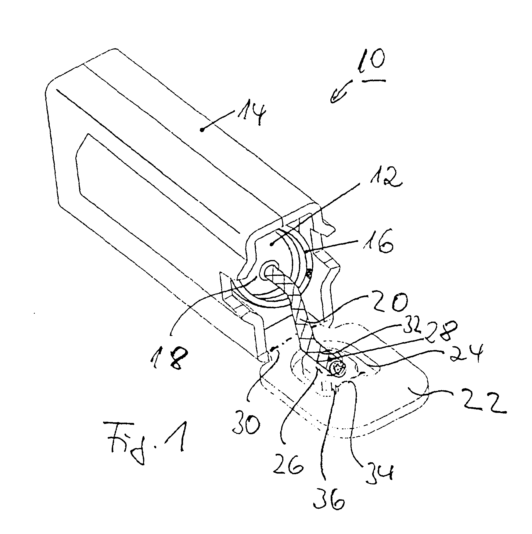
Description
Die Erfindung bezieht sich auf eine Bürstenhalterung für eine Kohlebürste umfassend ein vorderseitig offenes quader- oder köcherförmiges Gehäuse, in dem die Kohlebürste mittels eines auf diese einwirkenden Federelements axial verschiebbar ist, wobei von der Kohlebürste ein elektrischer Leiter wie Litze ausgeht, der mit dem Gehäuse in dessen rückseitiger Stirnwandung verbunden wie verschweißt ist.The invention relates to a brush holder for a carbon brush comprising a front-open cuboid or quiver-shaped housing, in which the carbon brush is axially displaceable by means of a spring element acting on it, an electric conductor such as a strand starting from the carbon brush, which connects with the housing whose rear end wall is connected as welded.
Entsprechende Halterungen werden zur Führung von Schleifpolen verwendet, welche elektrischen Strom von einem ruhenden auf ein bewegliches Bauteil übertragen, beispielsweise vom Starter zum Anker eines Elektromotors. In diesem Fall erfolgt die Stromübertragung auf Schleifringe oder Kollektorlamellen. Entsprechende Elektromotoren sind häufig starken Beanspruchungen und Erschütterungen ausgesetzt.Corresponding brackets are used to guide grinding poles, which transmit electrical current from a stationary to a moving component, for example from the starter to the armature of an electric motor. In this case, the current is transferred to slip rings or collector plates. Corresponding electric motors are often exposed to heavy loads and shocks.
Bei einer Bürstenführung der zuvor beschriebenen Art verläuft die Litze entlang der rückseitigen Stirnwandung des Gehäuses, um sodann um 90° abgewinkelt zur Kohlebürste geführt zu werden. Da entsprechende Bürstenführungen erwähntermaßen starken Belastungen wie Erschütterungen ausgesetzt sein können, besteht die Gefahr, dass sich die Litze löst oder an der Biegestelle abbricht.In the case of a brush guide of the type described above, the strand runs along the rear end wall of the housing, in order then to be guided at an angle of 90 ° to the carbon brush. Since corresponding brush guides, as mentioned, can be exposed to heavy loads such as vibrations, there is a risk that the strand may come loose or break off at the bending point.
Der vorliegenden Erfindung liegt das Problem zu Grunde, einen Bürstenhalter so weiterzubilden, dass eine sichere Verbindung zwischen dem elektrischen Leiter und dem Gehäuse der Bürstenhalterung möglich ist, wobei gleichzeitig die Länge des elektrischen Leiters so kurz wie möglich gehalten werden soll.The present invention is based on the problem of developing a brush holder in such a way that a secure connection between the electrical conductor and the housing of the brush holder is possible, while at the same time the length of the electrical conductor should be kept as short as possible.
Erfindungsgemäß wird das Problem im wesentlichen dadurch gelöst, dass der elektrische Leiter von einem sich in oder in etwa in Längsrichtung des Gehäuses erstreckenden Abschnitt der rückseitigen Stirnwandung ausgeht. Dabei erstreckt der sich aus der rückseitigen Stirnwandung herausgebogene bzw. abgewinkelte Abschnitt vorzugsweise mittig in das Gehäuseinnere hinein.According to the invention, the problem is essentially solved in that the electrical conductor starts from a section of the rear end wall that extends in or approximately in the longitudinal direction of the housing. The section bent or angled out of the rear end wall preferably extends centrally into the interior of the housing.
Durch die erfindungsgemäßen Maßnahmen wird der elektrische Leiter wie Kohlelitze nicht mehr abgewinkelt, wenn das Gehäuse rückseitig verschlossen ist. Vielmehr verläuft die Kohlelitze stets in Längsrichtung des Gehäuses, so dass Erschütterungen und sonstige Belastungen nicht zu einem Abknicken oder Lösen des elektrischen Leiters führen. Da sich der Abschnitt, von dem der elektrische Leiter ausgeht, in das Gehäuseinnere erstreckt, liegt des weiteren der Vorteil vor, dass der elektrische Leiter kürzer ausgelegt sein kann, so dass sich eine Materialersparnis ergibt.As a result of the measures according to the invention, the electrical conductor such as carbon strand is no longer angled when the housing is closed on the rear. Rather, the carbon strand always runs in the longitudinal direction of the housing, so that vibrations and other loads do not lead to the electrical conductor being bent or released. Since the section from which the electrical conductor extends extends into the interior of the housing, there is the further advantage that the electrical conductor can be made shorter, so that material is saved.
Da die Kohlelitze im geschlossenen Zustand des Gehäuses einen quasi neutralen Verlauf aufweist und sich innerhalb des vorzugsweise als Schraubenfeder ausgebildeten Federelements erstreckt, sind unzulässige Belastungen des elektrischen Leiters nahezu ausgeschlossen.Since the carbon strand has a quasi-neutral course in the closed state of the housing and extends within the spring element, which is preferably designed as a helical spring, impermissible loads on the electrical conductor are almost impossible.
In Weiterbildung der Erfindung ist der Bereich der rückseitigen Stirnwand, mit dem der elektrische Leiter verbunden wie verschweisst wird, von einer U- oder teilkreisförmigen Aussparung umgeben, wobei der Bereich selbst über einen Steg in die rückseitige Stirnwandung übergeht. Der Steg wird sodann von einer Biegelinie durchsetzt, entlang der der von der Aussparung umgebende Bereich abgewinkelt wird, um bei die rückseitige Öffnung des Gehäuses verschließender Stirnwandung, der ein verlängerter Abschnitt einer Seitenwandung ist, innerhalb des Gehäuses und entlang dessen Längsachse zu verlaufen. Die Biegelinie, entlang der die rückseitige Stirnwandung zum Verschließen des Gehäuses gebogen wird, verläuft dabei parallel oder nahezu parallel zu der Biegelinie, entlang der Bereich gebogen wird, der mit dem elektrischen Leiter wie Litze verbunden wie verschweißt ist.In a further development of the invention, the area of the rear end wall to which the electrical conductor is connected as welded is surrounded by a U-shaped or part-circular cutout, the area itself merging into the rear end wall via a web. The web is then penetrated by a bending line, along which the area surrounding the recess is angled, around the end wall which closes the rear opening of the housing and which is an extended section of a side wall is to run inside the housing and along its longitudinal axis. The bending line, along which the rear end wall is bent to close the housing, runs parallel or almost parallel to the bending line, along which the area is bent, which is connected to the electrical conductor like a strand as is welded.
Die Biegelinie, um die der Bereich biegbar ist, mit dem der elektrische Leiter verbunden ist, sollte in etwa im Mittenbereich der rückseitigen Stirnwandung und somit bei rückseitig geschlossenem Gehäuse entlang dessen Mittelachse verlaufen.The bending line, around which the area to which the electrical conductor is connected should bend, should run approximately in the center area of the rear end wall and thus with the housing closed at the rear along its central axis.
Weitere Einzelheiten, Vorteile und Merkmale der Erfindung ergeben sich nicht nur aus den Ansprüchen, den diesen zu entnehmenden Merkmalen - für sich und/oder in Kombination -, sondern auch aus der nachfolgenden Beschreibung eines der Zeichnung zu entnehmenden bevorzugten Ausführungsbeispiels.Further details, advantages and features of the invention result not only from the claims, the features to be extracted from them - individually and / or in combination - but also from the following description of a preferred exemplary embodiment which can be seen from the drawing.
Es zeigen:
- Fig. 1
- eine perspektivische Darstellung einer Bürstenhalterung mit offener Rückseite,
- Fig. 2
- die Bürstenhalterung nach Fig. 1 in Seitenansicht,
- Fig. 3
- die Bürstenhalterung nach Fig. 1 in Draufsicht,
- Fig. 4
- eine Rückansicht der Bürstenhalterung nach Fig. 1, jedoch bei geschlossener Rückseite, und
- Fig. 5
- einen Schnitt entlang der Linie A-A in Fig. 4.
- Fig. 1
- a perspective view of a brush holder with an open back,
- Fig. 2
- 1 in side view,
- Fig. 3
- 1 in top view,
- Fig. 4
- a rear view of the brush holder of FIG. 1, but with the back closed, and
- Fig. 5
- a section along the line AA in Fig. 4th
In Fig. 1 ist eine Bürstenhalterung 10 für eine Kohlebürste 12 dargestellt, die im Ausführungsbeispiel in einem quaderförmigen Gehäuse 14 axial verschiebbar angeordnet ist. Hierzu wirkt auf die Rückseite der Kohlebürste 12 eine Schraubenfeder 16.In Fig. 1, a
Von der rückseitigen Stirnwandung 18 der Kohlebürste 12 geht ein elektrischer Leiter in Form einer Litze 20 aus, der mit der Rückseitenwandung 22 des Gehäuses 14 verschweisst wird. Die Rückseitenwandung 24 ist dabei ein verlängerter Abschnitt einer Seitenwandung 25 des Gehäuses 14. Im Ausführungsbeispiel handelt es sich hierbei um die Bodenwandung 25.An electrical conductor in the form of a
Erfindungsgemäß weist die Rückwandung 22 einen von einer U-förmigen Aussparung 24 umgebenen Bereich 26 auf, in dem die Kohlelitze 20 befestigt wie verschweißt wird. Dieser Schweißbereich ist mit dem Bezugszeichen 28 gekennzeichnet.According to the invention, the
Bevor die Rückwandung 22 entlang einer senkrecht zur Gehäuselängsachse verlaufenden Biegelinie 38 gebogen wird, um das Gehäuse 14 rückseitig zu verschließen, wird die Litze 20 mit einem Endabschnitt 32 mit dem Bereich 26 verschweißt. Der Abschnitt 32 verläuft dabei parallel zur Längsachse des Gehäuses 14.Before the
Der Bereich oder Abschnitt 26 der rückseitigen Stirnwandung 22 ist seinerseits um eine Biegelinie 34 biegbar, die parallel zu der Biegelinie 30, um die die Stirnwandung 22 biegbar ist, verläuft. Ferner verläuft die Biegelinie 34 innerhalb einer Einschnürung 36 zwischen dem Schweissbereich 26, 28 und der Rückwand 22 selbst.The region or
Wird das Gehäuse 14 verschlossen, so wird einerseits die Stirnwandung 22 um die Biegelinie 30 und andererseits der Bereich 26, in dem die Litze 22 angeschweisst ist, um die Biegelinie 34 derart gebogen, dass sich der Abschnitt 26 innerhalb des Gehäuses 14 entlang dessen Längsachse und vorzugsweise mittig in diesem erstreckt. Hierdurch bedingt wird die Litze 22 nicht abgeknickt, sondern verläuft vielmehr im wesentlichen in Längsrichtung des Gehäuses 14 und in dessen Mitte, so dass sich ein neutraler Verlauf ergibt. Ferner zeigt die Schnittdarstellung in Fig. 5, dass der umgebogene Abschnitt 26 und damit die Litze 32 von der Schraubenfeder 16 umgeben sind.If the
Claims (10)
dadurch gekennzeichnet,
dass der elektrische Leiter (20) von einem sich in oder in etwa in Längsrichtung des Gehäuses (14) erstreckenden Abschnitt (26) der rückseitigen Stirnwandung (22) ausgeht.Brush holder (10) for a carbon brush (12) comprising a cuboid or quiver-shaped housing (14) which is open on one side and in which the carbon brush can be axially displaced by means of a spring element (16) acting on it, an electrical conductor of the carbon brush such as a stranded wire ( 20), which is connected to the housing in its rear end wall (22) as welded,
characterized,
that the electrical conductor (20) starts from a section (26) of the rear end wall (22) which extends in or approximately in the longitudinal direction of the housing (14).
dadurch gekennzeichnet,
dass der elektrische Leiter (20) mit einem von dem entlang der Gehäuselängsachse verlaufenden Abschnitt (26) ausgehenden Leiterabschnitt (32) entlang oder in etwa entlang der Gehäuselängsachse und vorzugsweise mittig innerhalb des Gehäuses (14) verläuft.Brush holder according to claim 1,
characterized,
that the electrical conductor (20) with a conductor section (32) extending from the section (26) running along the longitudinal axis of the housing runs along or approximately along the longitudinal axis of the housing and preferably centrally within the housing (14).
dadurch gekennzeichnet,
dass der mit dem elektrischen Leiter (20) verbundene Abschnitt (26) der rückseitigen Stirnwandung (22) ein gebogener bzw. abgewinkelter Ausschnitt der Stirnwandung (22) ist und sich innerhalb des Gehäuses (14) erstreckt.Brush holder according to claim 1 or 2,
characterized,
that the section (26) of the rear end wall (22) connected to the electrical conductor (20) is a bent or angled section of the end wall (22) and extends within the housing (14).
dadurch gekennzeichnet,
dass die rückseitige Stirnwandung (22) ein umgebogener Abschnitt einer Seitenwandung (25) des Gehäuses (14) ist und dass der mit dem elektrischen Leiter (20) zu verbindende Abschnitt oder Bereich (26) in der rückseitigen Stirnwandung von einer U- oder teilkreisförmigen Aussparung (24) umgeben ist und über eine stegartige Verbindung (36) in den die stirnseitige Rückwandung (22) bildenden Bereich des Gehäuses (14) übergeht.Brush holder according to at least one of the preceding claims,
characterized,
that the rear end wall (22) is a bent section of a side wall (25) of the housing (14) and that the section or region (26) to be connected to the electrical conductor (20) in the rear end wall of a U-shaped or part-circular recess (24) is surrounded and merges via a web-like connection (36) into the area of the housing (14) forming the front rear wall (22).
dadurch gekennzeichnet,
dass der mit dem Leiter (20) verbundene Abschnitt oder Bereich (24) der rückseitigen Stirnwandung (22) um eine Biegelinie (34) biegbar ist, die parallel oder in etwa parallel zur Biegelinie (30) der rückseitigen Stirnwandung (22) verläuft.Brush holder according to at least one of the preceding claims,
characterized,
that the section or region (24) of the rear end wall (22) connected to the conductor (20) can be bent about a bending line (34) which runs parallel or approximately parallel to the bending line (30) of the rear end wall (22).
dadurch gekennzeichnet,
dass zwischen den Biegelinien (30, 34) die U- oder teilkreisförmige Aussparung (24) verläuft.Brush holder according to at least one of the preceding claims,
characterized,
that the U-shaped or part-circular recess (24) runs between the bending lines (30, 34).
dadurch gekennzeichnet,
dass die Biegelinie (34), um die der mit der Litze (20) verbundene Abschnitt (26) biegbar ist, in etwa mittig im Bereich der rückseitigen Stirnwandung (22) verläuft, der das Gehäuse (14) verschließt.Brush holder according to at least one of the preceding claims,
characterized,
that the bending line (34) about which the section (26) connected to the strand (20) can be bent runs approximately centrally in the region of the rear end wall (22) which closes the housing (14).
dadurch gekennzeichnet,
dass der elektrische Leiter (20) über einen senkrecht oder in etwa senkrecht zu den Biegelinien (30, 34) verlaufenden Abschnitt (32) mit dem Verbindungsbereich (26, 28) der rückseitigen Stirnwandung (22) verbunden ist.Brush holder according to at least one of the preceding claims,
characterized,
that the electrical conductor (20) is connected to the connecting region (26, 28) of the rear end wall (22) via a section (32) running perpendicular or approximately perpendicular to the bending lines (30, 34).
dadurch gekennzeichnet,
dass der elektrische Leiter (20) bzw. dessen Abschnitt (32) linien- oder punktförmig mit dem biegbaren Bereich (26) der rückseitigen Stirnwandung (26) verbunden wie verschweißt ist.Brush holder according to at least one of the preceding claims,
characterized,
that the electrical conductor (20) or its section (32) is connected in a line or point shape to the bendable region (26) of the rear end wall (26) as is welded.
dadurch gekennzeichnet,
dass der abgewinkelte Abschnitt (26) der rückseitigen Stirnwandung (22) bei geschlossenem Gehäuse (14) innerhalb des Federelements wie Schraubenfeder (16) verläuft.Brush holder according to at least one of the preceding claims,
characterized,
that the angled section (26) of the rear end wall (22) when the housing (14) is closed runs inside the spring element like a helical spring (16).
Applications Claiming Priority (2)
| Application Number | Priority Date | Filing Date | Title |
|---|---|---|---|
| DE19619004 | 1996-05-10 | ||
| DE19619004A DE19619004A1 (en) | 1996-05-10 | 1996-05-10 | Brush holder |
Publications (3)
| Publication Number | Publication Date |
|---|---|
| EP0806818A2 true EP0806818A2 (en) | 1997-11-12 |
| EP0806818A3 EP0806818A3 (en) | 1998-12-09 |
| EP0806818B1 EP0806818B1 (en) | 2004-04-28 |
Family
ID=7794025
Family Applications (1)
| Application Number | Title | Priority Date | Filing Date |
|---|---|---|---|
| EP97107717A Expired - Lifetime EP0806818B1 (en) | 1996-05-10 | 1997-05-12 | Brush holder |
Country Status (2)
| Country | Link |
|---|---|
| EP (1) | EP0806818B1 (en) |
| DE (2) | DE19619004A1 (en) |
Cited By (2)
| Publication number | Priority date | Publication date | Assignee | Title |
|---|---|---|---|---|
| EP1184959A1 (en) * | 2000-08-29 | 2002-03-06 | Mitsubishi Denki Kabushiki Kaisha | Brush holder for dynamo-electric machine |
| EP1311039A3 (en) * | 2001-11-09 | 2007-08-22 | Robert Bosch Gmbh | Electrical machine with brush holder |
Family Cites Families (4)
| Publication number | Priority date | Publication date | Assignee | Title |
|---|---|---|---|---|
| DE2004910A1 (en) * | 1970-02-04 | 1971-08-19 | Filipenko I | Brush unit for electrical machines, preferably for machines with slip rings |
| DE7041832U (en) * | 1970-11-12 | 1971-04-08 | Conradty C | Contact button for welding attachment to carbon brushes for brush holder |
| NL7017717A (en) * | 1970-12-04 | 1972-06-06 | ||
| DE8605529U1 (en) * | 1986-02-28 | 1987-06-25 | Siemens AG, 1000 Berlin und 8000 München | Carbon brush |
-
1996
- 1996-05-10 DE DE19619004A patent/DE19619004A1/en not_active Withdrawn
-
1997
- 1997-05-12 EP EP97107717A patent/EP0806818B1/en not_active Expired - Lifetime
- 1997-05-12 DE DE59711556T patent/DE59711556D1/en not_active Expired - Fee Related
Cited By (3)
| Publication number | Priority date | Publication date | Assignee | Title |
|---|---|---|---|---|
| EP1184959A1 (en) * | 2000-08-29 | 2002-03-06 | Mitsubishi Denki Kabushiki Kaisha | Brush holder for dynamo-electric machine |
| US7414346B1 (en) | 2000-08-29 | 2008-08-19 | Mitsubishi Denki Kabushiki Kaisha | Brush holder for dynamo-electric machine |
| EP1311039A3 (en) * | 2001-11-09 | 2007-08-22 | Robert Bosch Gmbh | Electrical machine with brush holder |
Also Published As
| Publication number | Publication date |
|---|---|
| EP0806818B1 (en) | 2004-04-28 |
| DE59711556D1 (en) | 2004-06-03 |
| DE19619004A1 (en) | 1997-11-13 |
| EP0806818A3 (en) | 1998-12-09 |
Similar Documents
| Publication | Publication Date | Title |
|---|---|---|
| DE202008016439U1 (en) | Cartridge Heater | |
| EP1510300B1 (en) | Electric tool | |
| EP3164930A1 (en) | Coil for an electric machine | |
| EP2837061B1 (en) | Contacting device for connecting an electrical conductor | |
| DE19936557C2 (en) | Automatic insulation penetrating connection device | |
| DE3726894C2 (en) | ||
| EP3136519B1 (en) | Connection device for connecting a conductor to a busbar | |
| EP0806818B1 (en) | Brush holder | |
| EP2219268A1 (en) | Connection element and method and device for ultrasound welding | |
| EP0513010A1 (en) | ELECTROMAGNETIC RELAY. | |
| EP0610221B1 (en) | Coil for an electromagnetic relay | |
| DE102021203309A1 (en) | Separating clamping element, stator electric machine and method for manufacturing a stator | |
| DE3719214A1 (en) | ELECTRICALLY CONDUCTIVE CONNECTION BETWEEN CONTINUOUS SECTIONS OF STRAIGHT RAILS | |
| DE3408023A1 (en) | Brush holder for electrical commutator machines | |
| DE19909825C5 (en) | Sleeve-shaped clamping element for stripping-free connection of electrical conductors | |
| DE4444718C2 (en) | Method for producing a sensor and sensor produced by this method | |
| EP1480290B1 (en) | Contact arrangement having a wire connection | |
| EP4109684B1 (en) | Contact device | |
| DE102020104417A1 (en) | Connection terminal | |
| DE3744855C2 (en) | Carbon brush holder assembly for commutator or slip-ring | |
| DE2808671A1 (en) | solderless connector for single strand wire - has integral contact springs arresting tensile forces on wire and reinforced by spring hooks | |
| EP3745562B1 (en) | Coil former with integrated contacting device | |
| EP0000731B1 (en) | Method of tapping an insulated electric cable | |
| DE19817062A1 (en) | Clip-on connector for joining wires together | |
| EP0555720A1 (en) | Electric machine |
Legal Events
| Date | Code | Title | Description |
|---|---|---|---|
| PUAI | Public reference made under article 153(3) epc to a published international application that has entered the european phase |
Free format text: ORIGINAL CODE: 0009012 |
|
| AK | Designated contracting states |
Kind code of ref document: A2 Designated state(s): DE FR GB IT |
|
| AX | Request for extension of the european patent |
Free format text: AL;LT;LV;SI |
|
| PUAL | Search report despatched |
Free format text: ORIGINAL CODE: 0009013 |
|
| AK | Designated contracting states |
Kind code of ref document: A3 Designated state(s): AT BE CH DE DK ES FI FR GB GR IE IT LI LU MC NL PT SE |
|
| 17P | Request for examination filed |
Effective date: 19990306 |
|
| RBV | Designated contracting states (corrected) |
Designated state(s): DE FR GB IT |
|
| 17Q | First examination report despatched |
Effective date: 20030225 |
|
| GRAP | Despatch of communication of intention to grant a patent |
Free format text: ORIGINAL CODE: EPIDOSNIGR1 |
|
| GRAS | Grant fee paid |
Free format text: ORIGINAL CODE: EPIDOSNIGR3 |
|
| GRAA | (expected) grant |
Free format text: ORIGINAL CODE: 0009210 |
|
| AK | Designated contracting states |
Kind code of ref document: B1 Designated state(s): DE FR GB IT |
|
| PG25 | Lapsed in a contracting state [announced via postgrant information from national office to epo] |
Ref country code: IT Free format text: LAPSE BECAUSE OF FAILURE TO SUBMIT A TRANSLATION OF THE DESCRIPTION OR TO PAY THE FEE WITHIN THE PRE;WARNING: LAPSES OF ITALIAN PATENTS WITH EFFECTIVE DATE BEFORE 2007 MAY HAVE OCCURRED AT ANY TIME BEFORE 2007. THE CORRECT EFFECTIVE DATE MAY BE DIFFERENT FROM THE ONE RECORDED.SCRIBED TIME-LIMIT Effective date: 20040428 Ref country code: GB Free format text: LAPSE BECAUSE OF FAILURE TO SUBMIT A TRANSLATION OF THE DESCRIPTION OR TO PAY THE FEE WITHIN THE PRESCRIBED TIME-LIMIT Effective date: 20040428 Ref country code: FR Free format text: LAPSE BECAUSE OF FAILURE TO SUBMIT A TRANSLATION OF THE DESCRIPTION OR TO PAY THE FEE WITHIN THE PRESCRIBED TIME-LIMIT Effective date: 20040428 |
|
| REG | Reference to a national code |
Ref country code: GB Ref legal event code: FG4D Free format text: NOT ENGLISH |
|
| REF | Corresponds to: |
Ref document number: 59711556 Country of ref document: DE Date of ref document: 20040603 Kind code of ref document: P |
|
| GBV | Gb: ep patent (uk) treated as always having been void in accordance with gb section 77(7)/1977 [no translation filed] |
Effective date: 20040428 |
|
| PLBE | No opposition filed within time limit |
Free format text: ORIGINAL CODE: 0009261 |
|
| STAA | Information on the status of an ep patent application or granted ep patent |
Free format text: STATUS: NO OPPOSITION FILED WITHIN TIME LIMIT |
|
| EN | Fr: translation not filed | ||
| 26N | No opposition filed |
Effective date: 20050131 |
|
| PGFP | Annual fee paid to national office [announced via postgrant information from national office to epo] |
Ref country code: DE Payment date: 20090520 Year of fee payment: 13 |
|
| PG25 | Lapsed in a contracting state [announced via postgrant information from national office to epo] |
Ref country code: DE Free format text: LAPSE BECAUSE OF NON-PAYMENT OF DUE FEES Effective date: 20101201 |