EP0806646A2 - Method and apparatus for heating and dispensing a liquid sample - Google Patents
Method and apparatus for heating and dispensing a liquid sample Download PDFInfo
- Publication number
- EP0806646A2 EP0806646A2 EP97302978A EP97302978A EP0806646A2 EP 0806646 A2 EP0806646 A2 EP 0806646A2 EP 97302978 A EP97302978 A EP 97302978A EP 97302978 A EP97302978 A EP 97302978A EP 0806646 A2 EP0806646 A2 EP 0806646A2
- Authority
- EP
- European Patent Office
- Prior art keywords
- container
- flame
- test tube
- heat
- liquid
- Prior art date
- Legal status (The legal status is an assumption and is not a legal conclusion. Google has not performed a legal analysis and makes no representation as to the accuracy of the status listed.)
- Withdrawn
Links
Images


Classifications
-
- B—PERFORMING OPERATIONS; TRANSPORTING
- B01—PHYSICAL OR CHEMICAL PROCESSES OR APPARATUS IN GENERAL
- B01L—CHEMICAL OR PHYSICAL LABORATORY APPARATUS FOR GENERAL USE
- B01L3/00—Containers or dishes for laboratory use, e.g. laboratory glassware; Droppers
- B01L3/50—Containers for the purpose of retaining a material to be analysed, e.g. test tubes
- B01L3/502—Containers for the purpose of retaining a material to be analysed, e.g. test tubes with fluid transport, e.g. in multi-compartment structures
-
- B—PERFORMING OPERATIONS; TRANSPORTING
- B01—PHYSICAL OR CHEMICAL PROCESSES OR APPARATUS IN GENERAL
- B01L—CHEMICAL OR PHYSICAL LABORATORY APPARATUS FOR GENERAL USE
- B01L3/00—Containers or dishes for laboratory use, e.g. laboratory glassware; Droppers
- B01L3/02—Burettes; Pipettes
- B01L3/0289—Apparatus for withdrawing or distributing predetermined quantities of fluid
- B01L3/0293—Apparatus for withdrawing or distributing predetermined quantities of fluid for liquids
-
- B—PERFORMING OPERATIONS; TRANSPORTING
- B01—PHYSICAL OR CHEMICAL PROCESSES OR APPARATUS IN GENERAL
- B01L—CHEMICAL OR PHYSICAL LABORATORY APPARATUS FOR GENERAL USE
- B01L7/00—Heating or cooling apparatus; Heat insulating devices
-
- G—PHYSICS
- G01—MEASURING; TESTING
- G01N—INVESTIGATING OR ANALYSING MATERIALS BY DETERMINING THEIR CHEMICAL OR PHYSICAL PROPERTIES
- G01N35/00—Automatic analysis not limited to methods or materials provided for in any single one of groups G01N1/00 - G01N33/00; Handling materials therefor
- G01N2035/00346—Heating or cooling arrangements
- G01N2035/00425—Heating or cooling means associated with pipettes or the like, e.g. for supplying sample/reagent at given temperature
-
- G—PHYSICS
- G01—MEASURING; TESTING
- G01N—INVESTIGATING OR ANALYSING MATERIALS BY DETERMINING THEIR CHEMICAL OR PHYSICAL PROPERTIES
- G01N35/00—Automatic analysis not limited to methods or materials provided for in any single one of groups G01N1/00 - G01N33/00; Handling materials therefor
- G01N35/10—Devices for transferring samples or any liquids to, in, or from, the analysis apparatus, e.g. suction devices, injection devices
- G01N35/1079—Devices for transferring samples or any liquids to, in, or from, the analysis apparatus, e.g. suction devices, injection devices with means for piercing stoppers or septums
Abstract
The present specification describes the use of flame-free heat to safely dispense hazardous biological and chemical samples from a container (200) such as a test tube. Heat is applied to an inverted container (200) having a cannula (300) which passes through the cover (220) of the container (200). The heat causes expansion of the contents of the container (200) creating a positive pressure differential between the inside of the container (200) and the outside of the container (200), forcing the contents of the container (200) to flow through the cannula (300). A flame-free heating element (70) is connected to a power source (60) to heat the container (200).
Description
- The present invention relates to a method and apparatus for use in dispensing a liquid sample.
- More particularly, the present invention is directed to heating biological and chemical substances and dispensing biological and chemical samples from a container, such as a test tube. The present invention has particular application to medical and laboratory diagnostics. It is often necessary to perform testing and analysis of biological and chemical substances which are routinely stored within conventional containers such as test tubes. The invention further relates to the dispensing of hazardous liquids from containers without a risk of exposure to the technician who is handling the container. Therefore, the invention is generally related to the field of laboratory and worker safety.
- In performing certain laboratory tests on chemical or biological substances, it is often necessary to apply heat to the substance undergoing testing. It may be necessary to safely dispense portions of a liquid from a container onto a glass slide without contaminating the liquid and without exposing the technician to liquid, which may be hazardous.
- Methods currently exist for heating the contents of containers. For example, bunsen burners are often used to apply heat to test tubes, beakers, crucibles and other containers. However, these heating methods and apparatus are cumbersome and the heat may be far in excess of what is needed. Further, there may be circumstances where it is not desired to have a flame in a laboratory environment.
- When dispensing liquid samples from containers, it is often necessary to isolate the liquid sample from the laboratory technician for safety reasons, such as where the sample is a hazardous or infectious substance. Another reason to isolate the sample from the technician is to prevent contamination of the sample. Certain tests require the technician to "place" a liquid sample on a glass slide. For example, placing the blood on a slide or substrate is an important step that is required for many hematologic diagnoses. It is undesirable to expose a technician to the blood, since it may contain a disease, infection or virus, such as the HIV virus.
- According to the present invention there is provided a method of dispensing a liquid sample from within a container closed by a stopper at one end comprising the steps of:
- piercing the stopper with a cannula to equalize the pressure inside the container with the pressure external to the container; and
- increasing the pressure inside the container relative to the pressure external to the container by creating a flame-free temperature differential between the inside of the container and the outside of the container, thereby causing at least some of the liquid to flow through the cannula.
- According to a further feature of the present invention there is provided an apparatus for generating heat, for heating a test tube comprising:
- an electrically actuated, flame-free heating element for contacting the test tube;
- a power source, in electrical communication with the flame-free heating element; and
- a thermally insulated support for the flame-free heating element.
- The present invention thus provides a unique, flame-free heater to allow laboratory technicians to easily heat samples which are to be tested, and to monitor samples which are undergoing testing, as well as monitor the testing procedures. The present invention may thus be used to safely dispense samples of liquid onto a glass slide without the application of physical force.
- In accordance with one aspect of the invention, a heating element is placed on a finger of a laboratory technician and the finger of the technician is moved into contact with, or in the vicinity of, the sample to be heated. The heating element, which is flame-free, is insulated from the finger of the laboratory technician and energized by a portable power source, such as a battery. The power source may be located on a hand covering such as a glove or wrist support worn by the technician.
- Another aspect of the present invention is to provide an inexpensive, portable, heating element which is easily use to heat samples, and which is safe yet powerful enough to provide the necessary amount of heat.
- The heating element may be used to safely dispense hazardous biological and chemical samples, without the application of physical force. In one embodiment, a cannula is inserted though a rubber stopper of a sealed container, such as a test tube. The container is then inverted and placed over the surface on which the liquid is to be dispensed. Because pressure is equalized, the liquid within the container does not immediately dispense through the cannula. The heating element of the present invention is then applied to the exterior surface of the container. As the heat is conducted through the container wall, the temperature of the contents will increase and the volume of the contents will expand. A positive pressure differential is created between the inside of the container and the outside of the container by the expanding volume of the contents within the container. This pressure differential forces some of the liquid from inside the container to flow through the cannula.
- If the contents of the container are maintained at a temperature below body temperature, such as room temperature, the body heat from the hand of the technician may provide a sufficient temperature gradient to cause liquid from the container to be dispensed through the cannula. The effectiveness of this technique is increased by refrigerating the container and its contents prior to applying heat.
- It is an aspect of the invention to provide a method and apparatus to safely dispense hazardous samples.
- It is another aspect of the invention to provide a method and apparatus to safely dispense blood which is suspected of carrying a disease or infection, including the HIV virus, without the application of force.
- The aspects and advantages of the present invention, together with other advantages which may be attained by its use, will become more apparent upon reading the following detailed description of the invention, which is given by way of example, with reference to the accompanying drawings, wherein like reference numerals identify corresponding components, and in which: -
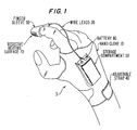
- Figure 1 is a diagrammatic illustration of one embodiment of heating apparatus for use in the present invention;
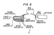
- Figure 2 is a diagrammatic, partially cross-sectional illustration of the construction of the embodiment of Figure 1;
- Figure 3 is a diagrammatic illustration of the method and apparatus of the embodiment shown in Figures 1 and 2 used to apply heat to a liquid sample;
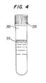
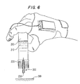
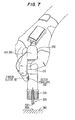
- Figures 4, 5, 6 and 7 are cross-sectional illustrations of the method and apparatus whereby the heating apparatus of Figures 1 and 2 is used to safely dispense a hazardous substance from a storage container; and
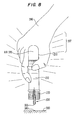
- Figure 8 is a cross-sectional illustration of the method and apparatus of an alternative embodiment of safely dispensing a hazardous substance from a storage container, where the body heat from the hand of a technician is used to apply heat to the storage container.
- Referring to the accompanying drawings,
heating apparatus 5 used in the present invention includes aglove 10, flexible and insulated wire leads 20 andfinger sleeve 30. The wire leads 20 are preferably flexible and insulated. Theglove 10 covers the palm and back of the hand and includes an adjustable strap 40 so that the glove may be snugly secured over the hand. The strap may be of the hook and loop type fastener or other conventional design. Theglove 10 also contains astorage compartment 50 to hold an energy source in the form of abattery 60, although other energy sources may be alternatively employed. - The
finger sleeve 30 includes aresistive heating surface 70 which generates heat in response to the energy from thebattery 60. Preferably, theresistive heating surface 70 is constructed of a material such as Kapton® which provides suitable heat in response to a low (9 volt) voltage from thebattery 60. Thebattery 60 is connected through a snap-fit connector 65 to wire leads 20. The wire leads 20 connect throughlead connection 90 toheating surface 70 at thefinger sleeve 30. Thelead connection 90 is permanent, as by crimping or soldering, or alternatively may be removable as with a mating plug. In thefinger sleeve 30, anouter latex envelope 100 andinner latex envelope 110 surround theheating surface 70.Thermal insulation 120 is placed between theinner envelope 110 and theheating surface 70. The finger of the laboratory technician is thus insulated fran any heat generated by the heating element bythermal insulation 120. Thethermal insulation 120 is preferably foam or other conventional insulation. - Current flows from
battery 60 throughbattery connector 80 and along wire leads 20 and theheating surface 70 increases in temperature. The heat fromsurface 70 radiates through theouter envelope 100, and the technician may heat samples by merely touching theouter envelope 100 to the sample, or placing theouter envelope 100 in close proximity to the sample. Theheating surface 70 is preferably contoured such that it conforms to surfaces which are perpendicular or parallel to the finger of the laboratory technician. - Figure 3 is an example of use of the apparatus with a
test tube 130 which has adrip gravity feed 140, and where the fluid is received in apetri dish 150. If it is desired to heat the contents of thetest tube 130, to immediately obtain fluid for testing purposes, it is undesirable to use a conventional burner. This is because conventional burners are impractical in that the burner would have to be set up at the test tube location and adjusted to provide the proper temperature at the proper distance. Additionally, a burner would require proper orientation to prevent drops from the test tube from falling into the burner itself. Of course the flame from the burner, if not carefully controlled, could crack or break the test tube. - Using the present invention, the laboratory technician touches the
outer envelope 100 ofheating surface 70 to the test tube. The heat transfer causes the temperature of the contents of the test tube to rise and the drops of liquid are dispensed at an accelerated rate. When theheating surface 70 is removed, the liquid cools to ambient temperature and resumes its prior output rate. - There are other advantages of the present invention. If the biological sample is stored below room (ambient) temperature, the use of the present invention quickly increases the temperature of the sample to ambient temperature for dispensing of the sample. Thus one laboratory technician may monitor numerous experiments in a quick and efficient manner, simply by contacting various containers with the heated finger sleeve. It should be appreciated that in addition to contacting the test tube or container with the heated finger sleeve, the present invention contemplates alterative methods for heating the sample. For example, the heating element may be placed on the palm portion of the
glove 10, rather than on afinger sleeve 30. Thefinger sleeve 30 may be supplied in a sterile packaging prior to use, to ensure that the sample is not contaminated. Multiple finger sleeves connected to one or more power sources may be used such that more than one finger sleeve contains a heating surface. As is known in the art, a control may be installed to vary the current from the power source and consequently the temperature of theheating surface 70. An on/off switch may also be provided to theheating apparatus 5. - Referring to Figures 4, 5, 6 and 7, a
test tube 200 contains liquid 210 which may be blood that is suspected to contain a disease or infection, including the HIV virus. Arubber stopper 220 seals the test tube to prevent accidental spillage and to prevent contamination of the liquid 210. A technician holds thetest tube 200 and acannula 300 is placed through therubber stopper 220. Thiscannula 300 has ahollow channel 350 bored or formed therein and apointed tip 354 to pierce through therubber stopper 220. Alternatively, thestopper 220 may have a preformed hole therein for allowing insertion of thecannula 300. As used herein, the term "pierce" is intended to cover all methods of inserting thecannula 300 through therubber stopper 220. and includes both manual insertion of the cannula and insertion with a mechanized apparatus. - After the cannula is inserted through the stopper, the
test tube 200 is inverted but the pressure inside of the test tube is equal to the pressure outside the test tube and no liquid is dispensed. Theouter envelope 100 of thefinger sleeve 30 is then placed in contact with the outer surface of thetest tube 200. Heat fromheating surface 70 is conducted onto the outer surface of thetest tube 200. This heat is transferred though the wall of thetest tube 200 and conducted to the liquid 210 within thetest tube 200 to the liquid 210 which expands, causing an increase in pressure inside thetest tube 200. A pressure differential is created between the inside and outside of thetest tube 200, which forces liquid 210 to flow throughchannel 350 ontosurface 380 as asample 390. The apparatus and method include heating anair pocket 395 in the test tube in addition to, or instead of, heating theliquid 210. The expansion of heated air causes the creation of a pressure differential and forces liquid 210 through thechannel 350. - Referring to Figure 8, the
heating apparatus 5 has been eliminated and the technician holds thetest tube 200. Thebody heat 397 from the hand of the technician heats the contents of thetest tube 200, particularly theair pocket 395 andliquid 210. The resulting pressure differential forces sample liquid throughchannel 350. As a result, asample 390 is disposed ontosurface 380. When the test tube and its contents are at room temperature, a human hand wrapped around the test tube can provide a sufficient temperature differential to cause liquid to flow through thecannula 300. However, it may be desirable to increase the temperature differential. To accomplish this procedure, the test tube and its contents may be stored in a refrigerator. The resulting temperature differential when the refrigerated test tube 200 (containing refrigerated liquid 210) is held by a human hand will be higher than if thetest tube 200 and liquid 210 were at room temperature. The refrigeration method may also be used to increase the effectiveness of dispensing a liquid sample when using theheating apparatus 5, as described with respect to Figures 4, 5, 6, and 7.
Claims (8)
- A method of dispensing a liquid sample (390) from within a container (200) closed by a stopper (220) at one end comprising the steps of:piercing the stopper (220) with a cannula (300) to equalize the pressure inside the container (200) with the pressure external to the container (200); andincreasing the pressure inside the container (200) relative to the pressure external to the container (200) by creating a flame-free temperature differential between the inside of the container (200) and the outside of the container (200), thereby causing at least some of the liquid to flow through the cannula (300).
- A method as claimed in claim 1, in which the step of creating a flame-free temperature differential includes transferring heat from a human hand to the container (200).
- A method as claimed in claim 1 or 2, further comprising, prior to the step of increasing the pressure inside the container (200), the step of cooling the container (200).
- A method as claimed in claim 1, 2 or 3, in which the step of creating a flame-free temperature differential comprises conducting electrical power to heat the container (200).
- An apparatus for generating heat, for heating a test tube (200) comprising:an electrically actuated, flame-free heating element (70) for contacting the test tube (200);a power source (60), in electrical communication with the flame-free heating element (70); anda thermally insulated support (30,100,110,120) for the flame-free heating element (70).
- Apparatus as claimed in claim 5, in which the thermally insulated support (30,100,110,120) is part of a glove (10).
- Apparatus as claimed in claim 5, in which the glove (10) includes a storage compartment (50) for holding the power source (60).
- Apparatus as claimed in any of claims 5, 6 or 7, in which the flame-free heating element (70) is an electrical resistance heater.
Applications Claiming Priority (4)
| Application Number | Priority Date | Filing Date | Title |
|---|---|---|---|
| US1694296P | 1996-05-06 | 1996-05-06 | |
| US16942 | 1996-05-06 | ||
| US74704596A | 1996-11-12 | 1996-11-12 | |
| US747045 | 1996-11-12 |
Publications (2)
| Publication Number | Publication Date |
|---|---|
| EP0806646A2 true EP0806646A2 (en) | 1997-11-12 |
| EP0806646A3 EP0806646A3 (en) | 1998-09-09 |
Family
ID=26689248
Family Applications (1)
| Application Number | Title | Priority Date | Filing Date |
|---|---|---|---|
| EP97302978A Withdrawn EP0806646A3 (en) | 1996-05-06 | 1997-05-01 | Method and apparatus for heating and dispensing a liquid sample |
Country Status (2)
| Country | Link |
|---|---|
| EP (1) | EP0806646A3 (en) |
| JP (1) | JPH10185771A (en) |
Citations (8)
| Publication number | Priority date | Publication date | Assignee | Title |
|---|---|---|---|---|
| DE3704757A1 (en) * | 1987-02-16 | 1988-08-25 | Klaus Winkler | Heating device for laboratory vessels |
| GB2211111A (en) * | 1987-10-21 | 1989-06-28 | Saxon Micro Limited | Micropipette and method of operation |
| FR2645410A1 (en) * | 1989-04-10 | 1990-10-12 | Gonzalez Eric | Self-contained heating glove liner |
| EP0409650A2 (en) * | 1989-07-21 | 1991-01-23 | Helena Laboratories Corporation | Apparatus for discharging contents of a sealed container |
| WO1992010294A1 (en) * | 1990-12-04 | 1992-06-25 | Manninen Antti P | Electrically heated reaction vessel |
| US5286453A (en) * | 1992-04-02 | 1994-02-15 | Pope Carolyn M | Device for dispensing a biological fluid from a sealed vacuum tube |
| US5397026A (en) * | 1993-01-21 | 1995-03-14 | Helena Laboratories Corporation | Method for discharging contents of a sealed container |
| WO1996000614A1 (en) * | 1994-06-30 | 1996-01-11 | Zia Yassinzadeh | Sample collection and manipulation apparatus and method |
-
1997
- 1997-05-01 EP EP97302978A patent/EP0806646A3/en not_active Withdrawn
- 1997-05-06 JP JP11568097A patent/JPH10185771A/en active Pending
Patent Citations (8)
| Publication number | Priority date | Publication date | Assignee | Title |
|---|---|---|---|---|
| DE3704757A1 (en) * | 1987-02-16 | 1988-08-25 | Klaus Winkler | Heating device for laboratory vessels |
| GB2211111A (en) * | 1987-10-21 | 1989-06-28 | Saxon Micro Limited | Micropipette and method of operation |
| FR2645410A1 (en) * | 1989-04-10 | 1990-10-12 | Gonzalez Eric | Self-contained heating glove liner |
| EP0409650A2 (en) * | 1989-07-21 | 1991-01-23 | Helena Laboratories Corporation | Apparatus for discharging contents of a sealed container |
| WO1992010294A1 (en) * | 1990-12-04 | 1992-06-25 | Manninen Antti P | Electrically heated reaction vessel |
| US5286453A (en) * | 1992-04-02 | 1994-02-15 | Pope Carolyn M | Device for dispensing a biological fluid from a sealed vacuum tube |
| US5397026A (en) * | 1993-01-21 | 1995-03-14 | Helena Laboratories Corporation | Method for discharging contents of a sealed container |
| WO1996000614A1 (en) * | 1994-06-30 | 1996-01-11 | Zia Yassinzadeh | Sample collection and manipulation apparatus and method |
Also Published As
| Publication number | Publication date |
|---|---|
| JPH10185771A (en) | 1998-07-14 |
| EP0806646A3 (en) | 1998-09-09 |
Similar Documents
| Publication | Publication Date | Title |
|---|---|---|
| US6235010B1 (en) | Closed system specimen collection container | |
| US4813432A (en) | Swab transport system | |
| US5700695A (en) | Sample collection and manipulation method | |
| CA1121681A (en) | Syringe like apparatus with removable capillary cartridge | |
| US5078970A (en) | Apparatus for withdrawing a liquid sample from a sample vessel and transferring it | |
| US20020041621A1 (en) | Temperature sensing device for selectively measuring temperature at desired locations along an intravenous fluid line | |
| US7484399B2 (en) | System, apparatus and method for dispensing chemical vapor | |
| US20070008160A1 (en) | Sterilization confirmation tester and test pack | |
| JPS58129362A (en) | Injector for on-column capillary gas chromatograph | |
| BRPI0609898A2 (en) | in situ antigen retrieval and staining apparatus, reaction module, method for treating a microscope slide, and reconfigurable reagent dispensing strip | |
| US4244917A (en) | Sample pyrolysis oven | |
| US4877036A (en) | Swab transport system | |
| HK1007797A1 (en) | Disposable sensing device for real time fluid analysis | |
| US20230404544A1 (en) | Self-contained sampling device for processing whole blood | |
| EP3877737B1 (en) | System and method for testing closure integrity of a sealed container at cryogenic temperatures | |
| BR112019027771A2 (en) | method, extraction instrument, distribution instrument and a kit for pre-treatment of a particular biological sample | |
| JP2021097998A (en) | Sample collection device, system and method for extracting and collecting sample of fluid of user | |
| US6939514B1 (en) | Method and apparatus for dispensing and distributing biological sample | |
| EP0806646A2 (en) | Method and apparatus for heating and dispensing a liquid sample | |
| HU182440B (en) | Test tube for microbiologic tests | |
| EP1656092B1 (en) | Closure device for a container | |
| US20190282151A1 (en) | Systems and methods for mixing drawn fluids | |
| US5396049A (en) | Sterilization apparatus using electrically heated inert material as sterilizing media | |
| US20020136665A1 (en) | Swab assembly | |
| EP0806647A2 (en) | Method and apparatus for dispensing and distributing liquid sample |
Legal Events
| Date | Code | Title | Description |
|---|---|---|---|
| PUAI | Public reference made under article 153(3) epc to a published international application that has entered the european phase |
Free format text: ORIGINAL CODE: 0009012 |
|
| AK | Designated contracting states |
Kind code of ref document: A2 Designated state(s): DE FR GB IT |
|
| PUAL | Search report despatched |
Free format text: ORIGINAL CODE: 0009013 |
|
| AK | Designated contracting states |
Kind code of ref document: A3 Designated state(s): DE FR GB IT |
|
| 16A | New documents despatched to applicant after publication of the search report | ||
| STAA | Information on the status of an ep patent application or granted ep patent |
Free format text: STATUS: THE APPLICATION HAS BEEN WITHDRAWN |
|
| 18W | Application withdrawn |
Withdrawal date: 19981008 |