EP0806591B1 - Vorrichtung zur Bestimmung der Position einer Schaltwelle zum Wählen und Schalten eines Ganges in einem Fahrzeuggetriebe - Google Patents
Vorrichtung zur Bestimmung der Position einer Schaltwelle zum Wählen und Schalten eines Ganges in einem Fahrzeuggetriebe Download PDFInfo
- Publication number
- EP0806591B1 EP0806591B1 EP97107364A EP97107364A EP0806591B1 EP 0806591 B1 EP0806591 B1 EP 0806591B1 EP 97107364 A EP97107364 A EP 97107364A EP 97107364 A EP97107364 A EP 97107364A EP 0806591 B1 EP0806591 B1 EP 0806591B1
- Authority
- EP
- European Patent Office
- Prior art keywords
- activating member
- selector rod
- positions
- gear
- striker
- Prior art date
- Legal status (The legal status is an assumption and is not a legal conclusion. Google has not performed a legal analysis and makes no representation as to the accuracy of the status listed.)
- Expired - Lifetime
Links
- 230000003213 activating effect Effects 0.000 claims description 38
- 230000033001 locomotion Effects 0.000 claims description 20
- 230000000875 corresponding effect Effects 0.000 claims description 15
- 238000006243 chemical reaction Methods 0.000 claims description 12
- 230000007935 neutral effect Effects 0.000 claims description 12
- 238000013519 translation Methods 0.000 claims description 10
- 230000002596 correlated effect Effects 0.000 claims description 6
- 238000001514 detection method Methods 0.000 description 6
- 238000010586 diagram Methods 0.000 description 3
- 230000005540 biological transmission Effects 0.000 description 1
- 238000004519 manufacturing process Methods 0.000 description 1
- 238000005259 measurement Methods 0.000 description 1
- 238000012986 modification Methods 0.000 description 1
- 230000004048 modification Effects 0.000 description 1
- 238000012544 monitoring process Methods 0.000 description 1
- 238000012545 processing Methods 0.000 description 1
Images
Classifications
-
- A—HUMAN NECESSITIES
- A46—BRUSHWARE
- A46B—BRUSHES
- A46B15/00—Other brushes; Brushes with additional arrangements
- A46B15/0055—Brushes combined with other articles normally separate from the brushing process, e.g. combs, razors, mirrors
- A46B15/0081—Brushes with a scraper, e.g. tongue scraper
-
- F—MECHANICAL ENGINEERING; LIGHTING; HEATING; WEAPONS; BLASTING
- F16—ENGINEERING ELEMENTS AND UNITS; GENERAL MEASURES FOR PRODUCING AND MAINTAINING EFFECTIVE FUNCTIONING OF MACHINES OR INSTALLATIONS; THERMAL INSULATION IN GENERAL
- F16H—GEARING
- F16H59/00—Control inputs to control units of change-speed- or reversing-gearings for conveying rotary motion
- F16H59/68—Inputs being a function of gearing status
- F16H59/70—Inputs being a function of gearing status dependent on the ratio established
-
- Y—GENERAL TAGGING OF NEW TECHNOLOGICAL DEVELOPMENTS; GENERAL TAGGING OF CROSS-SECTIONAL TECHNOLOGIES SPANNING OVER SEVERAL SECTIONS OF THE IPC; TECHNICAL SUBJECTS COVERED BY FORMER USPC CROSS-REFERENCE ART COLLECTIONS [XRACs] AND DIGESTS
- Y10—TECHNICAL SUBJECTS COVERED BY FORMER USPC
- Y10S—TECHNICAL SUBJECTS COVERED BY FORMER USPC CROSS-REFERENCE ART COLLECTIONS [XRACs] AND DIGESTS
- Y10S74/00—Machine element or mechanism
- Y10S74/07—Indicators-sensors and meters
-
- Y—GENERAL TAGGING OF NEW TECHNOLOGICAL DEVELOPMENTS; GENERAL TAGGING OF CROSS-SECTIONAL TECHNOLOGIES SPANNING OVER SEVERAL SECTIONS OF THE IPC; TECHNICAL SUBJECTS COVERED BY FORMER USPC CROSS-REFERENCE ART COLLECTIONS [XRACs] AND DIGESTS
- Y10—TECHNICAL SUBJECTS COVERED BY FORMER USPC
- Y10T—TECHNICAL SUBJECTS COVERED BY FORMER US CLASSIFICATION
- Y10T74/00—Machine element or mechanism
- Y10T74/20—Control lever and linkage systems
- Y10T74/20012—Multiple controlled elements
- Y10T74/20018—Transmission control
- Y10T74/20177—Particular element [e.g., shift fork, template, etc.]
Definitions
- the present invention relates to a device for detecting the position of a selector rod for carrying out an action of selecting and an action of engaging a gear in a vehicle gearbox.
- Gearboxes for vehicles especially motor vehicles, in which a selector rod is able to move in axial translation and in angular rotation to select the row of the gears of the gearbox and engage/disengage them, are known.
- WO - A - 91 11638 discloses a gear position sensor used to indicate that one of a plurality of gear ratios has been engaged in a change-speed transmission.
- the gear position sensor comprises a sensing transducer component and a co-operable component which is movable relative to the sensing transducer component in a first direction and a second direction transverse to the first direction into any one of a plurality of predetermined attitudes, each of which corresponds to one of the ratios.
- the cooperation between the sensing transducer component and the co-operable component enables the sensing transducer component to provide a signal to indicate that a particular ratio has been engaged.
- FR - A - 2 707 360 discloses a device for detecting the engaged ratio in a mechanical gearbox comprising an internal element for operating the gearbox and a sensor for detecting the engagement of each ratio by monitoring the position of the internal element.
- Devices for detecting selector rod position comprising two position sensors connected to the rod and outputting signals correlated with the axial position and angular position, respectively, of the selector rod, are also known. These signals are conveniently fed to an electronic processing circuit that outputs a single information signal indicating the axial and angular position of the selector rod.
- the present invention provides a device for detecting the position of a selector rod for carrying out an action of selecting a gear row and an action of engaging/disengaging the selected gear in a vehicle gearbox, said rod being able to move in axial translation for one of said actions and in angular rotation about its longitudinal axis for another of said actions, said selector rod also being able to adopt, for each gear row, a neutral position and two positions of gear engagement, said device being characterized in that it comprises sensor means provided with an angularly mobile activating member and able to output a signal S correlated with the angular position of the activating member and motion conversion means interposed between said selector rod and said activating member to convert each of said movements of axial translation and of angular rotation of said selector rod into a single rotary movement of said activating member.
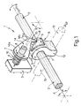
- the numeral 1 indicates, as a whole, a device for detecting the axial and angular position of a selector rod 2 of a vehicle gearbox (not shown).
- the selector rod 2 is able, in the embodiment described, to move in translation along its longitudinal axis A to select the row of the gear and in angular rotation about the axis A through a given angle ⁇ to engage/disengage the selected gear.
- the selector rod 2 in each row, can adopt a central neutral position and two opposing lateral positions of gear engagement that are angularly equidistant from the central position.
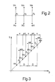
- Figure 2 shows a simplified diagram of the positions of engagement and selection of the selector rod; in this diagram the letters F 1 , F 2 , F 3 denote the central neutral positions of the rows that are selectable by translational movements of the selector rod 2, while the letters M 1 , M 2 , M 3 , M 4 , M 5 , RM denote the lateral positions of gear engagement obtained by angular rotations of the selector rod 2 about the axis A.
- selector rod 2 could be rotated angularly about the axis A to select the gear row and moved in translation along the axis A to engage/disengage the selected gear.
- the detection device 1 comprises ( Figure 1) a rotary sensor 3, for example a potentiometer, provided with an activating member 4 and able to output an electric signal correlated with the angular position ⁇ of the activating member 4, and a motion conversion device 5 interposed between the activating member 4 and the selector rod 2 to convert the aforesaid movements of both translation and rotation of the selector rod 2 into a rotary movement of the activating member 4.
- a rotary sensor 3 for example a potentiometer
- the motion conversion device 5 comprises a first and a second striker parts 6, 7 that slide over each other and are integrally connected to the selector rod 2 and activating member 4 respectively.
- the first striker part 6 comprises a supporting part 8 fixed on the selector rod 2 and having a cam 9, while the second striker part 7 consists of a follower in sliding contact with the cam 9. More specifically, the cam 9 is defined by a striker surface P extending along a portion of a helix having a given helix angle ⁇ , and the follower 7 is in sliding contact with the cam 9 along the aforesaid striker surface P.
- the supporting part 8 comprises a main portion 11 of generally cylindrical shape fixed on the selector rod 2 and a secondary integral portion 12 that extends radially away from the main portion 11 and is generally parallelepipedal in shape with rounded edges.
- the secondary portion 12 is coupled to an actuator rod 13 (shown in broken lines) extending transversely to the selector rod 2 and axially mobile in both directions for pushing or pulling the secondary portion 12 in order to cause an angular rotation in opposite directions through the angle ⁇ of the selector rod 2 about the axis A.
- an actuator rod 13 shown in broken lines
- the cam 9 is produced in the form of a body that projects out of the lateral surface of the main portion 11 and in plan view is approximately triangular.
- the follower 7 comprises an elongate connecting portion 14 extending radially from the activating member 4 with a first end portion 14a fixed on the activating member 4 and a second end portion 14b from which extends an integral tooth 15 with a contact portion 15a able to slide along the striker surface P. More specifically, to each movement of the tooth 15 along the striker surface P, caused by an axial or angular movement of the selector rod 2, there corresponds a rotary movement of the activating member 4 through an angle ⁇ correlated with the helix angle ⁇ of the portion of helix along which the striker surface P extends.
- the value of the helix angle ⁇ is decided in such a way as to obtain a signal S output by the rotary sensor 3 that is a function of the angular position ⁇ of the activating member 4 of this sensor 3 like that shown in Figure 3; also shown in this figure are the same letters from Figure 2 indicating the selected row and the engaged gear corresponding to the value of the angular position ⁇ .
- the helix angle ⁇ of the portion of helix along which the striker surface P extends defines a conversion relationship in which, lying between two angular positions ⁇ of the activating member 4 corresponding to respective neutral selector rod 2 positions belonging to adjacent rows, e.g. F 1 and F 2 or F 2 and F 3 , there are two intermediate angular positions ⁇ of the activating member 4 corresponding to respective positions of gear engagement of the selector rod 2 that each belong to a different one of the aforesaid adjacent rows - in the present example M 2 and M 3 or M 4 and M 5 , respectively.
- each of the intermediate angular positions ⁇ is approximately equidistant from the angular positions ⁇ of the activating member 4 corresponding on the one hand to the neutral position of that particular row, and on the other hand to the neighbouring position of gear engagement of the adjacent row.
- the helix angle ⁇ of the portion of helix around which the striker surface P extends defines a conversion relationship in which a first set of differences D, each calculated between two angular positions ⁇ of the activating member 4 corresponding to respective neutral selector rod 2 positions belonging to adjacent rows, e.g. F 1 and F 2 or F 2 and F 3 , are approximately equal to each other and a second set of differences d, each calculated between two angular positions ⁇ of the activating member 4 corresponding to respective positions of gear engagement of the selector rod 2 belonging to one particular row, that is, in this example M 1 and M 2 or M 3 and M 4 , respectively, are approximately two thirds of each of the first differences D.
- each difference calculated between two angular positions ⁇ of the activating member 4 corresponding to respective positions of gear engagement of the selector rod 2 in adjacent rows and indicated by numerically consecutive subscripts in Figure 2, e.g. M 2 and M 3 is approximately equal to one half of each of the second differences d and each difference calculated between two angular positions ⁇ of the activating member 4 corresponding respectively to a neutral position and a position of gear engagement of the selector rod 2 in one particular row, e.g. F 1 and M 2 or F 1 and M 1 , is also approximately equal to one half of each of the second differences d.
- the detection device 1 also comprises ( Figure 1) opposing parts 16 (shown schematically) connected to the follower 7 for keeping the contact portion 15a of the tooth 15 pressed against the striker surface P; these opposing parts 16 may for example be of elastic type and in particular, as shown in Figure 1, may take the form of a helical torsion spring.
- the shape of the cam 9 described above permits a one-to-one relationship to be established between an axial and angular position of the selector rod 2 and an angular position of the activating member 4.
- the rotary movement of the activating member 4 causes a change in the value of the output signal S of the rotary sensor 3, which can therefore be used to identify the axial and angular position of the selector rod 2 unambiguously.
- the detection device 1 directly outputs a single electrical signal correlated unambiguously with the angular and axial position of the selector rod 2. Secondly, the detection device 1 is simple, reliable, inexpensive to manufacture and compact.
- the cam 9 could take the form of a groove (not shown) in the lateral surface of the main portion 11.
Landscapes
- Engineering & Computer Science (AREA)
- General Engineering & Computer Science (AREA)
- Mechanical Engineering (AREA)
- Gear-Shifting Mechanisms (AREA)
- Control Of Transmission Device (AREA)
- Control Of Position Or Direction (AREA)
Claims (12)
- Vorrichtung (1) zur Erfassung der Position einer Schaltstange (2) zur Durchführung des Vorgangs der Wahl einer Zahnradreihe und des Vorgangs des Einrückens/Ausrückens des gewählten Ganges in einem Fahrzeuggetriebe, wobei sich die Stange (2) für einen der Vorgänge in einer axialen Parallelverschiebung und für den anderen der Vorgänge in einer Winkeldrehung um ihre Längsachse (A) bewegen kann, wobei die Schaltstange (2) für jede Zahnradreihe auch eine neutrale Stellung und zwei Stellungen mit eingelegtem Gang einnehmen kann, wobei die Vorrichtung (1) dadurch gekennzeichnet ist, daß sie folgendes umfaßt: eine Sensoreinrichtung (3), die mit einem Betätigungselement (4) versehen ist, das eine Winkelbewegung ausführen kann, und die ein mit der Winkelposition (β) des Betätigungselements (4) korreliertes Signal S abgeben kann, und eine Bewegungsumwandlungseinrichtung (5), die zwischen der Schaltstange (2) und dem Betätigungselement (4) angeordnet ist, um jede der Bewegungen der axialen Parallelverschiebung und der Winkeldrehung der Schaltstange (2) in eine einzige Drehbewegung des Betätigungselements (4) umzuwandeln.
- Vorrichtung nach Anspruch 1, dadurch gekennzeichnet, daß die Bewegungsumwandlungseinrichtung (5) eine erste und zweite Anschlageinrichtung (6, 7) umfaßt, die gegeneinander verschieblich sind; wobei die erste Anschlageinrichtung (6) mit der Stange (2) verbunden ist und die zweite Anschlageinrichtung (7) mit dem Betätigungselement (4) verbunden ist.
- Vorrichtung nach Anspruch 2, dadurch gekennzeichnet, daß die erste und zweite Anschlageinrichtung (6, 7) ein Stützteil (8) mit einem Nocken (9) und einem mit dem Nocken (9) in Gleitkontakt stehenden Mitnehmer (7) umfassen.
- Vorrichtung nach Anspruch 3, dadurch gekennzeichnet, daß der Nocken durch eine Anschlagfläche (P) begrenzt wird, die sich längs eines Abschnitts einer Schraubenlinie mit einem vorgegebenen Steigungswinkel (γ) erstreckt, und der Mitnehmer (7) entlang der Anschlagfläche (P) mit dem Nocken (9) in Gleitkontakt steht.
- Vorrichtung nach Anspruch 3 oder 4, dadurch gekennzeichnet, daß das Stützteil (8) einstückig mit der Schaltstange (2) verbunden ist.
- Vorrichtung nach einem der Ansprüche 3 bis 5, dadurch gekennzeichnet, daß das Stützteil (8) einen Hauptabschnitt (11) von allgemein zylindrischer Form umfaßt, der einstückig mit der Schaltstange (2) verbunden ist, und daß der Nocken (9) einen aus der Seitenfläche des Hauptabschnitts (11) ragenden Körper umfaßt.
- Vorrichtung nach einem der Ansprüche 3 bis 6, dadurch gekennzeichnet, daß der Mitnehmer (7) einstückig mit dem Betätigungselement (4) verbunden ist.
- Vorrichtung nach einem der Ansprüche 3 bis 7, dadurch gekennzeichnet, daß der Mitnehmer (7) einen langgestreckten, sich radial von dem Betätigungselement (4) erstreckenden Verbindungsabschnitt (14) mit einem an diesem Betätigungselement (4) befestigten ersten Endabschnitt (14a) und einem zweiten Endabschnitt (14b) umfaßt, von dem ein Zahn (15) mit einem Kontaktabschnitt (15a) ausgeht, der an der Anschlagfläche (P) entlanggleiten kann.
- Vorrichtung nach Anspruch 8, dadurch gekennzeichnet, daß sie eine mit dem Mitnehmer (7) verbundene Gegeneinrichtung (16) umfaßt, um den Kontaktabschnitt (15a) des Zahnes (15) gegen die Anschlagfläche (P) gedrückt zu halten.
- Vorrichtung nach einem der vorhergehenden Ansprüche, dadurch gekennzeichnet, daß die Bewegungsumwandlungseinrichtung ein Umwandlungsverhältnis definiert, bei dem zwischen zwei, den zu angrenzenden Reihen gehörigen jeweiligen Neutralstellungen (F1, F2, F3) der Schaltstange (2) entsprechenden Winkelpositionen (β) des Betätigungselements (4) zwei Zwischenwinkelpositionen (β) des Betätigungselements (4) liegen, die jeweiligen Schaltstellungen (M2-M3, M4-M5) der Schaltstange (2) entsprechen, die jeweils zu einer anderen angrenzenden Reihe gehören; und daß die Gänge entsprechend den jeweiligen Schaltstellungen (M2-M3, M4-M5) aufeinanderfolgen und jede der Zwischenwinkelpositionen (β) ungefähr gleich weit von den Winkelstellungen (β) des Betätigungselements (4) beabstandet ist, die einerseits der Neutralstellung (F1, F2, F3) dieser bestimmten Reihe und andererseits der benachbarten Schaltstellung (M2-M3, M4-M5) der angrenzenden Reihe entsprechen.
- Vorrichtung nach einem der vorhergehenden Ansprüche, dadurch gekennzeichnet, daß die Bewegungsumwandlungseinrichtung eine Umwandlungsverhältnis definiert, bei dem ein erster Satz von Unterschieden (D), die jeweils zwischen zwei, den zu angrenzenden Reihen gehörigen jeweiligen Neutralstellungen (F1, F2, F3) der Schaltstange (2) entsprechenden Winkelpositionen (β) des Betätigungselements (4) berechnet werden, ungefähr gleich zueinander ist und bei der ein zweiter Satz von Unterschieden (d), die jeweils zwischen zwei, den zu einer bestimmten Reihe gehörigen jeweiligen Schaltstellungen (M1-M2, M3-M4, M5-RM) der Schaltstange (2) entsprechenden Winkelpositionen (β) des Betätigungselements (4) berechnet werden, ungefähr zwei Drittel von jedem der ersten Unterschiede (D) beträgt.
- Vorrichtung nach Anspruch 11, dadurch gekennzeichnet, daß jeder zwischen zwei, einer Neutralstellung und einer Schaltstellung einer Schaltstange (2) in einer bestimmten Reihe entsprechenden Winkelpositionen (β) des Betätigungselements (4) berechnete Unterschied ungefähr gleich der Hälfte von jedem der zweiten Unterschiede (d) ist.
Applications Claiming Priority (2)
| Application Number | Priority Date | Filing Date | Title |
|---|---|---|---|
| IT96TO000367A IT1285861B1 (it) | 1996-05-07 | 1996-05-07 | Dispositivo di rilevamento della posizione di un albero di comando per l'esecuzione di una manovra di selezione ed una manovra di innesto |
| ITTO960367 | 1996-05-07 |
Publications (2)
| Publication Number | Publication Date |
|---|---|
| EP0806591A1 EP0806591A1 (de) | 1997-11-12 |
| EP0806591B1 true EP0806591B1 (de) | 2000-08-30 |
Family
ID=11414610
Family Applications (1)
| Application Number | Title | Priority Date | Filing Date |
|---|---|---|---|
| EP97107364A Expired - Lifetime EP0806591B1 (de) | 1996-05-07 | 1997-05-05 | Vorrichtung zur Bestimmung der Position einer Schaltwelle zum Wählen und Schalten eines Ganges in einem Fahrzeuggetriebe |
Country Status (6)
| Country | Link |
|---|---|
| US (1) | US5845538A (de) |
| EP (1) | EP0806591B1 (de) |
| BR (1) | BR9702005A (de) |
| DE (1) | DE69702946T2 (de) |
| ES (1) | ES2150167T3 (de) |
| IT (1) | IT1285861B1 (de) |
Cited By (1)
| Publication number | Priority date | Publication date | Assignee | Title |
|---|---|---|---|---|
| US11541855B2 (en) * | 2018-05-04 | 2023-01-03 | Safran Landing Systems | Locking device with a pulse-controlled rotary lock |
Families Citing this family (12)
| Publication number | Priority date | Publication date | Assignee | Title |
|---|---|---|---|---|
| GB2338570B (en) * | 1998-10-28 | 2000-10-25 | Ho Keung Tse | Vehicle window transmissivity control |
| US6072390A (en) * | 1999-03-31 | 2000-06-06 | Daimlerchrysler Corporation | Position sensing system for manually operated shift lever of a vehicle transmission |
| DE19918508C2 (de) * | 1999-04-23 | 2001-04-19 | Daimler Chrysler Ag | Schaltvorrichtung |
| DE19929038A1 (de) * | 1999-06-25 | 2000-12-28 | Hydraulik Ring Gmbh | Wegmeß- und Kontrolleinrichtung für Kraftfahrzeuge |
| DE19929632A1 (de) * | 1999-06-29 | 2001-01-18 | Bosch Gmbh Robert | Vorrichtung zur Positionserfassung von zwei Achsbewegungen |
| US6736024B1 (en) | 2000-01-25 | 2004-05-18 | Ford Global Technologies, Llc | Method and apparatus for determining the position of a shift rail |
| US6211794B1 (en) | 2000-04-06 | 2001-04-03 | Borgwarner | Analog rotary position sensor |
| US6382040B1 (en) * | 2000-05-27 | 2002-05-07 | Ford Global Technologies, Inc. | Method and apparatus for determining the position of a shift rail |
| DE50204390D1 (de) * | 2002-03-26 | 2006-02-09 | Getrag Ford Transmissions Gmbh | Sensoranordnung zur Bestimmung der Schaltwalzenstellung |
| DE10229320A1 (de) * | 2002-06-29 | 2004-01-15 | Zf Friedrichshafen Ag | Schalteinrichtung |
| CN102937181A (zh) * | 2012-11-14 | 2013-02-20 | 哈尔滨宏泰伟业科技有限公司 | 自动机械变速箱液压选换挡操纵机构传感器 |
| CN103197723A (zh) * | 2013-01-02 | 2013-07-10 | 王光树 | 一种旋转拉力选位器 |
Family Cites Families (7)
| Publication number | Priority date | Publication date | Assignee | Title |
|---|---|---|---|---|
| GB1576024A (en) * | 1977-03-08 | 1980-10-01 | Olsson Erik Allan | Method and jig for ascertaining the deformation in a damaged vehicle |
| DE3218143A1 (de) * | 1982-05-14 | 1983-11-17 | Volkswagenwerk Ag, 3180 Wolfsburg | Anordnung zur identifizierung des jeweils eingelegten gangs eines mehrgaengigen getriebes |
| IT1206886B (it) * | 1987-02-03 | 1989-05-11 | Dea Spa | Attrezzatura riconfigurabile per il sostegno ed il posizionamento dicorpi particolarmente di pezzi atti ad essere misurati da una macchina di misura |
| GB8823961D0 (en) * | 1988-10-12 | 1988-11-16 | Automotive Prod Plc | Gear position sensor |
| GB2240372B (en) * | 1990-01-25 | 1994-03-02 | Automotive Products Plc | Gear position sensor |
| DE4314952C2 (de) * | 1993-05-06 | 2002-06-06 | Zf Sachs Ag | Vorrichtung zur Erfassung der Gangstellung eines Schaltgetriebes |
| FR2707360B1 (fr) * | 1993-07-08 | 1995-08-11 | Renault | Dispositif de détection du rapport engagé sur une boîte de vitesses mécanique. |
-
1996
- 1996-05-07 IT IT96TO000367A patent/IT1285861B1/it active IP Right Grant
-
1997
- 1997-05-05 EP EP97107364A patent/EP0806591B1/de not_active Expired - Lifetime
- 1997-05-05 DE DE69702946T patent/DE69702946T2/de not_active Expired - Fee Related
- 1997-05-05 ES ES97107364T patent/ES2150167T3/es not_active Expired - Lifetime
- 1997-05-06 US US08/841,793 patent/US5845538A/en not_active Expired - Fee Related
- 1997-05-07 BR BR9702005A patent/BR9702005A/pt not_active IP Right Cessation
Cited By (1)
| Publication number | Priority date | Publication date | Assignee | Title |
|---|---|---|---|---|
| US11541855B2 (en) * | 2018-05-04 | 2023-01-03 | Safran Landing Systems | Locking device with a pulse-controlled rotary lock |
Also Published As
| Publication number | Publication date |
|---|---|
| DE69702946D1 (de) | 2000-10-05 |
| ES2150167T3 (es) | 2000-11-16 |
| ITTO960367A1 (it) | 1997-11-07 |
| DE69702946T2 (de) | 2001-03-01 |
| EP0806591A1 (de) | 1997-11-12 |
| ITTO960367A0 (it) | 1996-05-07 |
| IT1285861B1 (it) | 1998-06-24 |
| US5845538A (en) | 1998-12-08 |
| BR9702005A (pt) | 1998-11-10 |
Similar Documents
| Publication | Publication Date | Title |
|---|---|---|
| EP0806591B1 (de) | Vorrichtung zur Bestimmung der Position einer Schaltwelle zum Wählen und Schalten eines Ganges in einem Fahrzeuggetriebe | |
| EP2926036B1 (de) | Drehende schaltvorrichtung für shift-by-wire-getriebe | |
| US4911031A (en) | Transmission control apparatus | |
| EP2283255B1 (de) | Verfahren und vorrichtung zur steuerung eines getriebes für ein kraftfahrzeug | |
| EP0438489B1 (de) | Fühler für den stand des getriebes | |
| JP2014080194A (ja) | 変速機のための作動装置 | |
| JPS59112319A (ja) | トランスミツシヨンシフト装置 | |
| EP1239192A3 (de) | Schaltvorrichtung für ein Kraftfahrzeug | |
| EP0513026B1 (de) | Getriebegangfühler | |
| KR890701388A (ko) | 전동장치 | |
| EP0373273B1 (de) | Getriebesteuerungsgerät | |
| GB2277784A (en) | A gear position detector | |
| CN104145142A (zh) | 传动装置保护系统 | |
| JP2009503389A (ja) | 変速機のための作動装置 | |
| EP3835624B1 (de) | Getriebestellglied | |
| US6457376B1 (en) | Travel measuring and control device for motor vehicle transmissions | |
| US4972052A (en) | Contact device for delivering electrical signals corresponding to the position of a movable body | |
| JP2019183966A (ja) | シフト切替機構の制御装置 | |
| KR102550066B1 (ko) | 차량용 자동변속 조작장치 | |
| EP3657049B1 (de) | Getriebestellglied | |
| EP1541463A2 (de) | Elektromechanische Steuereinheit insbesondere für Boote | |
| JP2003503664A (ja) | 2つの軸方向運動の位置検出装置 | |
| US20040017169A1 (en) | Control system for a robotized gearbox in a motor vehicle, with the ability to learn the position of the ratios or gears | |
| JP2638229B2 (ja) | 車輌用多段自動変速機の変速制御装置 | |
| EP0685667A1 (de) | Gangwähleinrichtung für ein Getriebe |
Legal Events
| Date | Code | Title | Description |
|---|---|---|---|
| PUAI | Public reference made under article 153(3) epc to a published international application that has entered the european phase |
Free format text: ORIGINAL CODE: 0009012 |
|
| AK | Designated contracting states |
Kind code of ref document: A1 Designated state(s): DE ES FR GB SE |
|
| 17P | Request for examination filed |
Effective date: 19970923 |
|
| 17Q | First examination report despatched |
Effective date: 19990312 |
|
| GRAG | Despatch of communication of intention to grant |
Free format text: ORIGINAL CODE: EPIDOS AGRA |
|
| RTI1 | Title (correction) |
Free format text: DEVICE FOR DETECTING THE POSITION OF A SELECTOR ROD FOR SELECTING AND ENGAGING A GEAR IN A VEHICLE GEARBOX |
|
| RTI1 | Title (correction) |
Free format text: DEVICE FOR DETECTING THE POSITION OF A SELECTOR ROD FOR SELECTING AND ENGAGING A GEAR IN A VEHICLE GEARBOX |
|
| GRAG | Despatch of communication of intention to grant |
Free format text: ORIGINAL CODE: EPIDOS AGRA |
|
| GRAH | Despatch of communication of intention to grant a patent |
Free format text: ORIGINAL CODE: EPIDOS IGRA |
|
| GRAH | Despatch of communication of intention to grant a patent |
Free format text: ORIGINAL CODE: EPIDOS IGRA |
|
| GRAA | (expected) grant |
Free format text: ORIGINAL CODE: 0009210 |
|
| AK | Designated contracting states |
Kind code of ref document: B1 Designated state(s): DE ES FR GB SE |
|
| REF | Corresponds to: |
Ref document number: 69702946 Country of ref document: DE Date of ref document: 20001005 |
|
| ET | Fr: translation filed | ||
| REG | Reference to a national code |
Ref country code: ES Ref legal event code: FG2A Ref document number: 2150167 Country of ref document: ES Kind code of ref document: T3 |
|
| PLBE | No opposition filed within time limit |
Free format text: ORIGINAL CODE: 0009261 |
|
| STAA | Information on the status of an ep patent application or granted ep patent |
Free format text: STATUS: NO OPPOSITION FILED WITHIN TIME LIMIT |
|
| 26N | No opposition filed | ||
| REG | Reference to a national code |
Ref country code: GB Ref legal event code: IF02 |
|
| PGFP | Annual fee paid to national office [announced via postgrant information from national office to epo] |
Ref country code: ES Payment date: 20060509 Year of fee payment: 10 |
|
| PGFP | Annual fee paid to national office [announced via postgrant information from national office to epo] |
Ref country code: SE Payment date: 20060510 Year of fee payment: 10 Ref country code: GB Payment date: 20060510 Year of fee payment: 10 |
|
| PGFP | Annual fee paid to national office [announced via postgrant information from national office to epo] |
Ref country code: FR Payment date: 20060529 Year of fee payment: 10 |
|
| PGFP | Annual fee paid to national office [announced via postgrant information from national office to epo] |
Ref country code: DE Payment date: 20060728 Year of fee payment: 10 |
|
| EUG | Se: european patent has lapsed | ||
| GBPC | Gb: european patent ceased through non-payment of renewal fee |
Effective date: 20070505 |
|
| REG | Reference to a national code |
Ref country code: FR Ref legal event code: ST Effective date: 20080131 |
|
| PG25 | Lapsed in a contracting state [announced via postgrant information from national office to epo] |
Ref country code: DE Free format text: LAPSE BECAUSE OF NON-PAYMENT OF DUE FEES Effective date: 20071201 |
|
| PG25 | Lapsed in a contracting state [announced via postgrant information from national office to epo] |
Ref country code: GB Free format text: LAPSE BECAUSE OF NON-PAYMENT OF DUE FEES Effective date: 20070505 |
|
| PG25 | Lapsed in a contracting state [announced via postgrant information from national office to epo] |
Ref country code: SE Free format text: LAPSE BECAUSE OF NON-PAYMENT OF DUE FEES Effective date: 20070506 |
|
| PG25 | Lapsed in a contracting state [announced via postgrant information from national office to epo] |
Ref country code: FR Free format text: LAPSE BECAUSE OF NON-PAYMENT OF DUE FEES Effective date: 20070531 |
|
| REG | Reference to a national code |
Ref country code: ES Ref legal event code: FD2A Effective date: 20070507 |
|
| PG25 | Lapsed in a contracting state [announced via postgrant information from national office to epo] |
Ref country code: ES Free format text: LAPSE BECAUSE OF NON-PAYMENT OF DUE FEES Effective date: 20070507 |