EP0806561B1 - A control circuit for a heater with variable resistance associated with a sensor for detecting oxygen in exhaust gases - Google Patents
A control circuit for a heater with variable resistance associated with a sensor for detecting oxygen in exhaust gases Download PDFInfo
- Publication number
- EP0806561B1 EP0806561B1 EP97107132A EP97107132A EP0806561B1 EP 0806561 B1 EP0806561 B1 EP 0806561B1 EP 97107132 A EP97107132 A EP 97107132A EP 97107132 A EP97107132 A EP 97107132A EP 0806561 B1 EP0806561 B1 EP 0806561B1
- Authority
- EP
- European Patent Office
- Prior art keywords
- heater
- control circuit
- measurement resistor
- path
- circuit according
- Prior art date
- Legal status (The legal status is an assumption and is not a legal conclusion. Google has not performed a legal analysis and makes no representation as to the accuracy of the status listed.)
- Expired - Lifetime
Links
Images


Classifications
-
- F—MECHANICAL ENGINEERING; LIGHTING; HEATING; WEAPONS; BLASTING
- F02—COMBUSTION ENGINES; HOT-GAS OR COMBUSTION-PRODUCT ENGINE PLANTS
- F02D—CONTROLLING COMBUSTION ENGINES
- F02D41/00—Electrical control of supply of combustible mixture or its constituents
- F02D41/02—Circuit arrangements for generating control signals
- F02D41/14—Introducing closed-loop corrections
- F02D41/1438—Introducing closed-loop corrections using means for determining characteristics of the combustion gases; Sensors therefor
- F02D41/1493—Details
- F02D41/1494—Control of sensor heater
Definitions
- the present invention relates to a control circuit for a heater with variable resistance associated with a sensor for detecting oxygen in exhaust gases, particularly for an internal combustion engine of a motor vehicle.
- control circuit comprising:
- Oxygen sensors or lambda probes are normally used in motor-vehicle catalytic converters for measuring the quantity of oxygen present in the exhaust gases.
- Lambda probes operate correctly only if their temperature is high enough. At normal running speeds this is ensured by the high temperature of the exhaust gases.
- a heater associated with the sensor Upon starting, the activation of a heater associated with the sensor generates an additional quantity of heat such as to heat the sensor quickly and limit emissions.
- the electrical resistance of the heater is of the type which is variable positively with temperature (the PTC type). Its value increases progressively from a minimum upon activation to a much higher steady value when the temperature of the gases has stabilized.
- the current absorbed by the heater at the starting stage may consequently even be one order of magnitude higher than that absorbed in the steady state. Naturally this current also depends upon the supply voltage (the battery voltage).
- the functionality of the heater can be monitored by accurate detection of the current passing through the measurement resistor associated with the heater and the functionality of the probe can thus be deduced for a subsequent adjustment operation, if necessary. (Compare with DE-A-35 17 252, Fig. 3 or 6)
- the current measurement has to be particularly accurate but this conflicts with two contrasting requirements relating to the resistance of the measurement resistor.
- this resistor has to have a very low resistance.
- the voltage drop in a measurement resistor with low resistance would be a few mV giving rise to large measurement errors, which also arise because of the offset and drift which are not negligible in comparison with the useful signal.
- An object of the present invention is to provide an improved control circuit for a heater with variable resistance associated with an oxygen sensor, which overcomes the problems outlined above and which, in particular, is suitable for enabling the sensor to operate at the most uniform possible temperature, to ensure precise and reliable measurements.
- the measurement resistor can be of an optimal size since the current flowing in the heater passes through this resistor only after it has substantially reached the steady value.
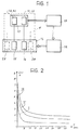
- Figure 1 shows, in the form of a block diagram, a system 11 for controlling the emissions of a motor-vehicle internal combustion engine 12.
- the system 11 operates in association with a fuel-injection system 13 and a catalytic converter 14. It comprises a sensor 15 for detecting oxygen in the exhaust gases (a lambda probe) associated with an electric heater 16 and an electronic control unit 17 including a microprocessor 18.
- the lambda probe 15 can provide signals indicative of the quantity of oxygen present in the exhaust gases.
- the electronic unit 17 uses these signals to regulate the injection system 13 so as to achieve an optimal air-fuel ratio.
- the probe 15 is mounted in the converter 14 together with the electric heater 16.
- This heater comprises a resistor Rr1 (see Figure 3) having a first terminal connected to one pole of a direct-current voltage source, for example, the positive pole of the motor-vehicle battery.
- the electronic unit 17 comprises a control circuit 19 associated with the heater 16 and connected to the other terminal of the heater resistor Rr1 in order to control the connection of this resistor to earth.
- the resistance of the resistor Rr1 is variable positively with temperature.
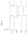
- Figure 2 shows three curves I, II and III, representing the current Ir1 in the resistor Rr1 as functions of time T for three possible values of the resistance of this resistor which correspond to different dissipation levels, for example, of 5W, 12W and 18W, respectively.
- the current Ir1 varies progressively from a maximum upon activation of the heater to a steady minimum value which is lower than the maximum value by almost one order of magnitude.
- a control circuit 19 has the purpose of monitoring the current Ir1 in the resistor Rr1 of the heater 16.
- This circuit which is connected to a terminal of a measurement (shunt) resistor Rs of which the other terminal is earthed, comprises an amplifier 20 connected to the measurement resistor Rs and switching devices 21, 22 driven by the microprocessor 18.
- the amplifier 20 is an operational amplifier and its inputs are connected to the measurement resistor Rs by means of a low-pass filter including a resistor Rf and a capacitor Cf.
- the output of the amplifier 20 provides a signal indicative of the current Ir1 at an analog/digital conversion input A/D of the microprocessor 18.
- the switching devices 21, 22 comprise, for example, two transistors PW1 and PW2 associated with respective driver circuits 23, 24.
- the transistors PW1 and PW2 are preferably of the PowerMOS type and their drains are connected to the resistor Rr1 of the heater 16.
- the source of PW1 is connected directly to earth whereas the source of PW2 is connected to earth through the measurement resistor Rs.
- the respective inputs of the driver circuits 23 and 24 are connected to corresponding output terminals IN1 and IN2 of the microprocessor 18.
- a Zener diode may advantageously be interposed between the drain and the gate of each transistor PW1 and PW2 for protection against overvoltages which may be generated owing to inductive effects in the heater supply lines.
- the switching devices 21 and 22, suitably driven by the microprocessor 18, can define two different routes for the connection of the resistor Rr1 to earth.
- the resistor Rr1 is connected to earth through PW1
- the resistor Rr1 is connected to earth through PW2 and the measurement resistor Rs.
- the resistor Rs detects the current Ir1 flowing in the heating resistor Rr1.
- the strategy for the control of the heater 16 provides for the microprocessor 18 to make the transistor PW1 conductive temporarily upon activation.
- the microprocessor 18 has associated storage in which a predetermined time period long enough for the heater 16, and hence the lambda probe 15, to reach the steady state, is defined.
- the microprocessor 18 After activation and when the time period stored has elapsed, the microprocessor 18 switches the switches 21 and 22, cutting off PW1 and making PW2 conductive. In this situation, the current Ir1 flowing in the heater 16 passes through the transistor PW2 and the measurement resistor Rs and the microprocessor 18 can acquire, at its input A/D, a signal indicative of the level of the current Ir1.
- Figure 4 shows examples of curves of the signals VIN1, VIN2 for driving the transistors PW1 and PW2, of the current Ir1, and of the output voltage VOP of the operational amplifier 20.
- the transistor PW1 is of a size such as to withstand the maximum transient intensity of Ir1 which may occur with variations of the type of heater, as well as with variations of the supply voltage Vbat and of the initial temperature.
- the transistor PW2 on the other hand, can be of a size such as to withstand the maximum intensity of the current Ir1 when the heater 16 has reached a steady temperature.
- the measurement resistor Rs is in turn of a size such that the operational amplifier 20 is in its optimal operating conditions in the steady state.
- the timing of the switchings described above provides for the transistor PW1 to be cut off before the transistor PW2 becomes conductive.
- the current Ir1 in the heater 16 is cut off temporarily before and after the acquisition of the current value Ir1. This has no appreciable effect on the temperature of the lambda probe, however.
- the heater has a high thermal inertia in comparison with the very short switching times of the transistors PW1 and PW2.
- the interruption of the current in the heater in the switching stages can, however, be avoided, by making PW2 conductive before PW1 is cut off and then making PW1 conductive before PW2 is cut off.
- the examples of curves of the signals shown in Figure 5 correspond to this method of operation.
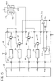
- the variant of Figure 6 relates to a situation in which provision is made for the use of a further lambda probe, indicated 25 in Figure 1, for controlling emissions.
- a second heater 28 is now provided, associated with the second lambda probe 25 and including a resistor Rr2, the resistance of which is also of the PTC type.
- the resistor Rr2 has a terminal connected to the battery.
- the control circuit of the two lambda probes which is indicated 29 in Figures 1 and 6, comprises a first portion identical to the circuit 19 described above for controlling the heater 16 and the switches 21, 22 and an additional portion for monitoring the current Ir2 in the heater 28 associated with the second lambda probe.
- the circuit 29 is connected to a microprocessor 32 similar to the microprocessor 18 which, in addition to the input A/D and the output terminals IN1 and IN2, has two further output terminals IN3 and IN4 for two further switches 30, 31 associated with the heater 28 (Rr2).
- the currents Ir1 and Ir2 are monitored alternately with time sharing by the microprocessor 32 and the two heaters 16 and 28 are controlled alternately.
- the driving structure is thus duplicated in comparison with that of the circuit 19 of Figure 3, whereas there is advantageously only one circuit portion for detecting the currents.
- the microprocessor 32 can in fact arrange for the current Ir1 or Ir2 of one of the two heaters to flow through the measurement resistor Rs at a time, when its intensity is to be acquired.
- the switches 30, 31 may comprise transistors PW3 and PW4 and respective driver circuits 33, 34.
- the transistors PW3 and PW4 are also advantageously of the PowerMOS type and have their drains connected to the resistor Rr2 of the heater 28.
- the source of PW3 is connected directly to earth, whereas the source of PW4 is connected to earth through the shunt resistor Rs.
- the drivers 33 and 34 are in turn interposed between the gates of PW3 and PW4 and the output terminals IN3 and IN4 of the microprocessor 32.
- the microprocessor 32 is arranged in a manner such that, for each activation of the heaters, PW1 and PW3 are made conductive in succession and PW2 and PW4 are kept cut off. Then, without any change in the conditions of the transistors PW3 and PW4, PW1 is cut off and PW2 is made conductive, after sufficient time for the heater 16, and hence the lambda probe 15, to reach a steady temperature.
- the current Ir1 flowing in the heater 16 now passes through the transistor PW2 and the measurement resistor Rs.
- the microprocessor 32 then acquires the level of the current Ir1 and then returns the transistors PW1 and PW2 to the initial conditions to allow the current Ir1 to flow directly to earth.
- PW3 is cut off whilst PW4 is made conductive.
- the current Ir2 which flows in the heater 28 now passes through the transistor PW4 and the measurement resistor Rs and the microprocessor 32 acquires the intensity of the current Ir2.
- the transistors PW3 and PW4 are then returned to the initial conditions, enabling the current Ir2 to flow directly to earth.
- the microprocessor 32 can be programmed suitably to acquire the values of the currents Ir1 and Ir2 periodically, repeating the sequence described above.
- the currents Ir1 and Ir2 flowing in the heaters 18 and 26 are also interrupted temporarily before and after reading without a significant effect on the temperature.
- the circuit 29 which performs the function of controlling and monitoring the currents Ir1 and Ir2 of the two heaters 16 and 28 may be formed in a single custom-made integrated circuit.
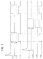
- Figure 7 shows examples of the curves of the driver signals VIN1, VIN2, VIN3 and VIN4, of the currents Ir1 and Ir2, and of the output voltage VOP of the operational amplifier 20 for the circuit of Figure 6.
- the transistor PW3 is of a size such as to withstand the maximum intensity of Ir2 which may occur with variations of the supply voltage and of the initial temperature.
- the transistor PW4, on the other hand, is of a size such as to withstand the maximum intensity of the current Ir2 when the heater 28 is in the steady state.
- the measurement resistor Rs is in turn of a size such that, in the steady state, the operational amplifier 20 is in optimal operating conditions both for the heater 16 and for the heater 28.
- the microprocessor 18 or 32 can detect any deterioration of the heater 16 or 28 upon the basis of the values acquired for the current Ir1 and/or Ir2. It can also implement a strategy for de-activating the heater 16 or 28 in optimal running conditions, increasing the life and reliability thereof.
Landscapes
- Engineering & Computer Science (AREA)
- Chemical & Material Sciences (AREA)
- Combustion & Propulsion (AREA)
- Mechanical Engineering (AREA)
- General Engineering & Computer Science (AREA)
- Measuring Oxygen Concentration In Cells (AREA)
- Combined Controls Of Internal Combustion Engines (AREA)
- Investigating Or Analyzing Materials By The Use Of Fluid Adsorption Or Reactions (AREA)
Description
- a measurement resistor which can be connected substantially in series with the heater, and
- detector means connected to the measurement resistor for providing a signal indicative of the current flowing in the resistor, and hence in the heater.
Claims (10)
- A control circuit for a heater (16, 28) with variable resistance associated with an oxygen sensor (15, 25), particularly for a motor-vehicle internal combustion engine, comprising:characterized in that it comprises:a measurement resistor (Rs) which can be connected substantially in series with the heater (16, 28), anddetector means (20) connected to the measurement resistor (Rs) for providing a signal (VOP) indicative of the current flowing in the resistor (Rs),switching means (PW1, PW2; PW3, PW4) for controlling the connection of the heater (16, 28) to a direct-current voltage source (Vbat) and the connection of the measurement resistor (Rs) in the supply circuit comprising the source (Vbat) and the heater (16, 28), andcontrol means (18, 32) arranged to drive the switching means (PW1, PW2; PW3, PW4) in a manner such that, each time the heater (16, 28) is activated, the measurement resistor (Rs) is kept disconnected from the supply circuit of the heater (16, 28) for a predetermined period of time and the measurement resistor (Rs) is then connected in the supply circuit of the heater (16, 28).
- A control circuit according to Claim 1, for controlling a plurality of heaters (16, 28) with variable resistance associated with respective oxygen sensors (15, 25), characterized in that it comprises a single measurement resistor (Rs), and in that the switching means (PW1, PW2; PW3, PW4) are connected to the heaters (16, 28) and to the measurement resistor (Rs) in a manner such as to enable the measurement resistor (Rs) selectively to be connected in series with each of the heaters (16, 28) sequentially.
- A control circuit according to Claim 2, characterized in that one terminal of the or each heater (16, 28) is connected to a pole of the voltage source (Vbat) and the other terminal is connected to the other pole of the source by a first or a second path, the first path comprising an electronic switch (PW1; PW3), and the second path comprising a second electronic switch (PW2; PW4) and the measurement resistor (Rs).
- A control circuit according to Claim 3, characterized in that the control means (18, 32) are arranged, upon each activation of the heater or heaters (16, 28), to bring about the initial connection of the or each heater (16, 28) to the second pole of the voltage source by the associated first path (PW1; PW3) and, after the predetermined initial period of time, to bring about the connection of the or each heater (16, 28) to the second pole of the voltage source by the associated second path (PW2, Rs; PW4, Rs).
- A control circuit according to Claim 4, characterized in that the control means (18, 32) are arranged to drive the switches (PW1, PW2; PW3, PW4) in a manner such that the connection of the or each heater (16, 28) to the second pole of the voltage source by the associated first path (PW1; PW3) is disabled before the connection via the associated second path (PW2, Rs; PW4, Rs) is enabled.
- A control circuit according to Claim 4, characterized in that the control means (18, 32) are arranged to drive the switches (PW1, PW2; PW3, PW4) in a manner such that the connection of the or each heater (16, 28) to the second pole of the voltage source by the associated first path (PW1; PW3) is disabled after the connection by the associated second path (PW2, Rs; PW4, Rs) has been enabled.
- A control circuit according to any one of Claims 2 to 6, characterized in that the first and second switches (PW1, PW3; PW2, PW4) associated with the or each heater (16, 28) are PowerMOS transistors.
- A control circuit according to any one of the preceding claims, characterized in that the detector means comprise a differential amplifier (20) connected to the measurement resistor (Rs).
- A control circuit according to Claim 8, characterized in that the amplifier (20) is connected to the measurement resistor (Rs) by means of a low-pass filter (Rf, Cf).
- A control circuit according to any one of the preceding claims, characterized in that the control means comprise a microprocessor (18, 32).
Applications Claiming Priority (2)
| Application Number | Priority Date | Filing Date | Title |
|---|---|---|---|
| IT96TO000378A IT1285863B1 (en) | 1996-05-08 | 1996-05-08 | CONTROL CIRCUIT FOR A VARIABLE RESISTANCE HEATER ASSOCIATED WITH AN EXHAUST GAS OXYGEN SENSOR. |
| ITTO960378 | 1996-05-08 |
Publications (2)
| Publication Number | Publication Date |
|---|---|
| EP0806561A1 EP0806561A1 (en) | 1997-11-12 |
| EP0806561B1 true EP0806561B1 (en) | 2000-06-07 |
Family
ID=11414619
Family Applications (1)
| Application Number | Title | Priority Date | Filing Date |
|---|---|---|---|
| EP97107132A Expired - Lifetime EP0806561B1 (en) | 1996-05-08 | 1997-04-30 | A control circuit for a heater with variable resistance associated with a sensor for detecting oxygen in exhaust gases |
Country Status (7)
| Country | Link |
|---|---|
| US (1) | US5970785A (en) |
| EP (1) | EP0806561B1 (en) |
| CN (1) | CN1145866C (en) |
| BR (1) | BR9700672A (en) |
| DE (1) | DE69702226T2 (en) |
| ES (1) | ES2147413T3 (en) |
| IT (1) | IT1285863B1 (en) |
Families Citing this family (4)
| Publication number | Priority date | Publication date | Assignee | Title |
|---|---|---|---|---|
| EP1790979A1 (en) * | 2005-11-24 | 2007-05-30 | Consultatie Implementatie Technisch Beheer B.V. | Electronic chemical trace detector |
| US20080099333A1 (en) * | 2006-10-26 | 2008-05-01 | Nair Balakrishnan Nair Vijayak | Control circuit for multiple oxygen sensor heater elements |
| US8014930B2 (en) * | 2008-10-30 | 2011-09-06 | GM Global Technology Operations LLC | System and method for determining oxygen sensor heater resistance |
| JP6214975B2 (en) * | 2013-09-10 | 2017-10-18 | 日本特殊陶業株式会社 | Load drive device and sensor control device |
Family Cites Families (12)
| Publication number | Priority date | Publication date | Assignee | Title |
|---|---|---|---|---|
| US4520653A (en) * | 1983-08-29 | 1985-06-04 | Ford Motor Company | Circuits for obtaining a voltage reading from a sensing element |
| JPS60235047A (en) * | 1984-05-07 | 1985-11-21 | Toyota Motor Corp | Method for controlling temperature of oxygen sensor with heater for internal-combustion engine |
| JPS60239664A (en) * | 1984-05-14 | 1985-11-28 | Nissan Motor Co Ltd | Heating apparatus of oxygen sensor |
| JPH07122627B2 (en) * | 1987-12-16 | 1995-12-25 | 日本電装株式会社 | Heater controller for oxygen concentration sensor |
| US5055269A (en) * | 1989-03-06 | 1991-10-08 | Bacharach, Inc | Temperature limited catalytic gas detector apparatus |
| US4993392A (en) * | 1989-04-24 | 1991-02-19 | Toyota Jidosha Kabushiki Kaisha | Apparatus for controlling heater for heating oxygen sensor |
| US5182519A (en) * | 1990-10-22 | 1993-01-26 | Mitsubishi Denki Kabushiki Kaisha | Heater control device for an air-fuel ratio sensor |
| DE4128385A1 (en) * | 1991-08-27 | 1993-03-04 | Bosch Gmbh Robert | METHOD AND DEVICE FOR MONITORING THE OPERATIONAL FUNCTION OF AN OXYGEN MEASURING PROBE HEATING |
| DE4221922C1 (en) * | 1992-07-03 | 1994-01-13 | Bosch Gmbh Robert | Warm tone sensor |
| US5454259A (en) * | 1993-08-02 | 1995-10-03 | Toyota Jidosha Kabushiki Kaisha | Failure detecting apparatus in temperature controller of air-fuel ratio sensor |
| US5392643A (en) * | 1993-11-22 | 1995-02-28 | Chrysler Corporation | Oxygen heater sensor diagnostic routine |
| DE4344961B4 (en) * | 1993-12-30 | 2004-05-06 | Robert Bosch Gmbh | Evaluation device for the signal of an oxygen probe |
-
1996
- 1996-05-08 IT IT96TO000378A patent/IT1285863B1/en active IP Right Grant
-
1997
- 1997-04-30 ES ES97107132T patent/ES2147413T3/en not_active Expired - Lifetime
- 1997-04-30 DE DE69702226T patent/DE69702226T2/en not_active Expired - Lifetime
- 1997-04-30 EP EP97107132A patent/EP0806561B1/en not_active Expired - Lifetime
- 1997-05-06 BR BR9700672A patent/BR9700672A/en not_active Application Discontinuation
- 1997-05-07 CN CNB971111472A patent/CN1145866C/en not_active Expired - Fee Related
- 1997-05-08 US US08/853,163 patent/US5970785A/en not_active Expired - Lifetime
Also Published As
| Publication number | Publication date |
|---|---|
| CN1183586A (en) | 1998-06-03 |
| IT1285863B1 (en) | 1998-06-24 |
| US5970785A (en) | 1999-10-26 |
| BR9700672A (en) | 1998-09-01 |
| DE69702226T2 (en) | 2000-10-12 |
| CN1145866C (en) | 2004-04-14 |
| ES2147413T3 (en) | 2000-09-01 |
| DE69702226D1 (en) | 2000-07-13 |
| ITTO960378A0 (en) | 1996-05-08 |
| EP0806561A1 (en) | 1997-11-12 |
| ITTO960378A1 (en) | 1997-11-08 |
Similar Documents
| Publication | Publication Date | Title |
|---|---|---|
| JP4295900B2 (en) | Heater control device for exhaust gas sensor | |
| KR970004673B1 (en) | Apparatus and method for driving and controlling electric consumers in particular heat plugs | |
| JP4209736B2 (en) | Engine control device | |
| US9752958B2 (en) | Load drive apparatus and sensor control apparatus | |
| US7536244B2 (en) | Failure diagnostic apparatus and method for an air-fuel ratio sensor | |
| US20080099333A1 (en) | Control circuit for multiple oxygen sensor heater elements | |
| JP5069796B2 (en) | Inspection device for sensor element functionality | |
| JPH05222993A (en) | System of driving inductive load | |
| EP0806561B1 (en) | A control circuit for a heater with variable resistance associated with a sensor for detecting oxygen in exhaust gases | |
| US9739823B2 (en) | Diagnostic circuit and method for the operation of a diagnostic circuit | |
| US11635472B2 (en) | Load driving device | |
| US5836156A (en) | Driving device of sensors and actuators | |
| US10837941B2 (en) | Electronic control unit | |
| US5929328A (en) | Method for checking the function of the electrical heater of a lambda probe in the exhaust line of an internal combustion engine | |
| JPH06501368A (en) | Servo motor control circuit configuration | |
| JPS5979847A (en) | Control apparatus of oxygen concentration sensor | |
| US5637786A (en) | Series parallel heated oxygen sensor heater control | |
| US7116110B1 (en) | Sensorless protection for electronic device | |
| KR20050071501A (en) | Method for identifying an overload current of an electric drive | |
| US11935338B2 (en) | Automotive electronic control unit | |
| KR20020060759A (en) | Control circuit and control method for a gas sensor | |
| JP4545215B2 (en) | Heater control device for exhaust gas sensor | |
| JPH10132868A (en) | Device for detecting current flowing in inductance | |
| KR970010979B1 (en) | Air-fuel ratio control system in oxidizer sensor to use heat resistor | |
| JP2546395B2 (en) | Oxygen sensor heater control failure diagnosis device |
Legal Events
| Date | Code | Title | Description |
|---|---|---|---|
| PUAI | Public reference made under article 153(3) epc to a published international application that has entered the european phase |
Free format text: ORIGINAL CODE: 0009012 |
|
| AK | Designated contracting states |
Kind code of ref document: A1 Designated state(s): DE ES FR GB SE |
|
| 17P | Request for examination filed |
Effective date: 19980418 |
|
| RAP3 | Party data changed (applicant data changed or rights of an application transferred) |
Owner name: MAGNETI MARELLI S.P.A. Owner name: STMICROELECTRONICS S.R.L. |
|
| GRAG | Despatch of communication of intention to grant |
Free format text: ORIGINAL CODE: EPIDOS AGRA |
|
| 17Q | First examination report despatched |
Effective date: 19990707 |
|
| GRAG | Despatch of communication of intention to grant |
Free format text: ORIGINAL CODE: EPIDOS AGRA |
|
| GRAH | Despatch of communication of intention to grant a patent |
Free format text: ORIGINAL CODE: EPIDOS IGRA |
|
| GRAH | Despatch of communication of intention to grant a patent |
Free format text: ORIGINAL CODE: EPIDOS IGRA |
|
| GRAA | (expected) grant |
Free format text: ORIGINAL CODE: 0009210 |
|
| AK | Designated contracting states |
Kind code of ref document: B1 Designated state(s): DE ES FR GB SE |
|
| REF | Corresponds to: |
Ref document number: 69702226 Country of ref document: DE Date of ref document: 20000713 |
|
| REG | Reference to a national code |
Ref country code: ES Ref legal event code: FG2A Ref document number: 2147413 Country of ref document: ES Kind code of ref document: T3 |
|
| ET | Fr: translation filed | ||
| PLBE | No opposition filed within time limit |
Free format text: ORIGINAL CODE: 0009261 |
|
| STAA | Information on the status of an ep patent application or granted ep patent |
Free format text: STATUS: NO OPPOSITION FILED WITHIN TIME LIMIT |
|
| 26N | No opposition filed | ||
| REG | Reference to a national code |
Ref country code: GB Ref legal event code: IF02 |
|
| REG | Reference to a national code |
Ref country code: FR Ref legal event code: PLFP Year of fee payment: 19 |
|
| PGFP | Annual fee paid to national office [announced via postgrant information from national office to epo] |
Ref country code: GB Payment date: 20150324 Year of fee payment: 19 Ref country code: SE Payment date: 20150324 Year of fee payment: 19 Ref country code: FR Payment date: 20150319 Year of fee payment: 19 |
|
| PGFP | Annual fee paid to national office [announced via postgrant information from national office to epo] |
Ref country code: ES Payment date: 20150408 Year of fee payment: 19 Ref country code: DE Payment date: 20150319 Year of fee payment: 19 |
|
| REG | Reference to a national code |
Ref country code: DE Ref legal event code: R119 Ref document number: 69702226 Country of ref document: DE |
|
| GBPC | Gb: european patent ceased through non-payment of renewal fee |
Effective date: 20160430 |
|
| REG | Reference to a national code |
Ref country code: FR Ref legal event code: ST Effective date: 20161230 |
|
| PG25 | Lapsed in a contracting state [announced via postgrant information from national office to epo] |
Ref country code: DE Free format text: LAPSE BECAUSE OF NON-PAYMENT OF DUE FEES Effective date: 20161101 Ref country code: GB Free format text: LAPSE BECAUSE OF NON-PAYMENT OF DUE FEES Effective date: 20160430 Ref country code: FR Free format text: LAPSE BECAUSE OF NON-PAYMENT OF DUE FEES Effective date: 20160502 |
|
| PG25 | Lapsed in a contracting state [announced via postgrant information from national office to epo] |
Ref country code: SE Free format text: LAPSE BECAUSE OF NON-PAYMENT OF DUE FEES Effective date: 20160501 |
|
| REG | Reference to a national code |
Ref country code: ES Ref legal event code: FD2A Effective date: 20180507 |
|
| PG25 | Lapsed in a contracting state [announced via postgrant information from national office to epo] |
Ref country code: ES Free format text: LAPSE BECAUSE OF NON-PAYMENT OF DUE FEES Effective date: 20160430 |
|
| PG25 | Lapsed in a contracting state [announced via postgrant information from national office to epo] |
Ref country code: ES Free format text: LAPSE BECAUSE OF NON-PAYMENT OF DUE FEES Effective date: 20160501 |