EP0806555B1 - Hitzeschild, insbesondere zur Abschirmung abgasführender Teile in Kraftfahrzeugen - Google Patents
Hitzeschild, insbesondere zur Abschirmung abgasführender Teile in Kraftfahrzeugen Download PDFInfo
- Publication number
- EP0806555B1 EP0806555B1 EP19960107012 EP96107012A EP0806555B1 EP 0806555 B1 EP0806555 B1 EP 0806555B1 EP 19960107012 EP19960107012 EP 19960107012 EP 96107012 A EP96107012 A EP 96107012A EP 0806555 B1 EP0806555 B1 EP 0806555B1
- Authority
- EP
- European Patent Office
- Prior art keywords
- heat shield
- shield according
- layers
- punched holes
- insulating layer
- Prior art date
- Legal status (The legal status is an assumption and is not a legal conclusion. Google has not performed a legal analysis and makes no representation as to the accuracy of the status listed.)
- Expired - Lifetime
Links
Images
Classifications
-
- F—MECHANICAL ENGINEERING; LIGHTING; HEATING; WEAPONS; BLASTING
- F01—MACHINES OR ENGINES IN GENERAL; ENGINE PLANTS IN GENERAL; STEAM ENGINES
- F01N—GAS-FLOW SILENCERS OR EXHAUST APPARATUS FOR MACHINES OR ENGINES IN GENERAL; GAS-FLOW SILENCERS OR EXHAUST APPARATUS FOR INTERNAL-COMBUSTION ENGINES
- F01N13/00—Exhaust or silencing apparatus characterised by constructional features
- F01N13/14—Exhaust or silencing apparatus characterised by constructional features having thermal insulation
-
- B—PERFORMING OPERATIONS; TRANSPORTING
- B60—VEHICLES IN GENERAL
- B60R—VEHICLES, VEHICLE FITTINGS, OR VEHICLE PARTS, NOT OTHERWISE PROVIDED FOR
- B60R13/00—Elements for body-finishing, identifying, or decorating; Arrangements or adaptations for advertising purposes
- B60R13/08—Insulating elements, e.g. for sound insulation
- B60R13/0876—Insulating elements, e.g. for sound insulation for mounting around heat sources, e.g. exhaust pipes
-
- F—MECHANICAL ENGINEERING; LIGHTING; HEATING; WEAPONS; BLASTING
- F01—MACHINES OR ENGINES IN GENERAL; ENGINE PLANTS IN GENERAL; STEAM ENGINES
- F01N—GAS-FLOW SILENCERS OR EXHAUST APPARATUS FOR MACHINES OR ENGINES IN GENERAL; GAS-FLOW SILENCERS OR EXHAUST APPARATUS FOR INTERNAL-COMBUSTION ENGINES
- F01N2260/00—Exhaust treating devices having provisions not otherwise provided for
- F01N2260/20—Exhaust treating devices having provisions not otherwise provided for for heat or sound protection, e.g. using a shield or specially shaped outer surface of exhaust device
Definitions
- the invention relates to a heat shield, in particular for shielding exhaust gas-carrying parts in motor vehicles, with at least a metallic one arranged between two cover layers Insulation layer.
- Heat sources such as exhaust manifolds, downpipes, turbochargers, Exhaust system and catalytic converter of a motor vehicle, give off their heat through radiation, heat conduction and convection to their surroundings.
- heat shields of various designs are used.
- these heat shields consist of one Insulation layer arranged between two cover or protective layers is.
- the insulation layer can be made from a poorly heat conductive Material, such as cardboard or nonwoven, exist.
- a good heat conductors also have an effect as insulation layers, which dissipate the heat to the side via their surface.
- DE 41 41 855 A discloses a heat shield with at least one metallic insulation layer arranged between two cover layers 1, 2, a perforated or perforated aluminum foil, with which the at least one insulation layer is formed by a foil structured by means of a plurality of perforations; this inevitably creates burrs on the perforations or perforations. These ridges are - as can be seen in Figure 1 of MTZ MOTORTECHNISCHE ZEITSCHRIFT, vol. 54, no. 6, June 1993, STUTTGART, pages 280-283 - jagged.
- the present invention has for its object a To create heat shield with a metallic insulation layer which is particularly light and has very good thermal insulation properties having.
- the object is achieved with a heat shield according to claim 1.
- the burr parts only cause punctiform thermal contacts neighboring layers or preferably also from Metal existing top layers.
- the burrs can advantageously be bent outwards. These bent ridges cause a selective doubling of the material thickness of the Sheet metal part or the film.
- To achieve a desired one Insulation layer thickness may be sufficient to use only one layer or fewer layers. This effect can still be seen increase that of both surfaces of at least one Insulation ply are introduced, so that Penetration ridges bent over both surfaces are.
- the weight of the heat shield can be different from a use significantly reduce structured metallic insulation layers.
- the Punctures also ensure good sound absorption, what when used as a shield from exhaust systems Motor vehicles another is significant advantage.
- a particularly high insulation and Sound absorption effect can be achieved when several Insulation layers are provided, the openings being adjacent Layers are staggered. The individual layers are only at certain points. Located between the layers an insulating air cushion.
- the at least one insulation layer can expediently pressed with the two cover layers his.
- the pressing process can also be advantageous Bending the penetration ridges can be achieved.
- the result is an extremely simple and inexpensive manufacturing process for the heat shield.
- With a particularly environmentally friendly Solution can be the at least one insulation layer from the same material as the top layers, for example made of aluminum or sheet steel.
- the heat shield can then as a whole, without disassembling individual parts beforehand, be recycled.
- the stability of the heat shield can be thereby increase that at least one of the cover layers at least can be provided with profiles on the inside. For improved sound absorption, at least one of the top layers with perforations, the one Reduce airborne noise
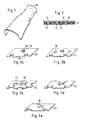
- the heat shield 10 is the Adapted shape of the component to be shielded, so that it is only very requires little installation space.
- Fig. 2 there is the heat shield 10 from three layers, an upper cover layer 11, one lower cover layer 12 and an insulation layer arranged between them 13, which is metallic.
- the top layers 11 and 12 are in example of unstructured sheet metal parts.
- the insulation layer 13 is formed by a sheet metal part into the perforations 14 and 15 are introduced, the penetration 14 of the surface facing the upper cover layer 12 and the Penetration 15 of the lower cover layer 11 facing Surface of the insulation layer 13 are introduced.
- Corresponding are the associated penetration ridges 16 and 17 opposite sides of the insulation layer 13.
- the insulation layer 13 was pressed with the cover layers 12 and 11, whereby the penetration ridges 16 and 17, which, as FIG. 3 shows, slotted, can be jagged or tongue-shaped, bent outwards become.
- the ridges 16 and 17 form punctiform thermal bridges with the top layers 11 and 12, over which only a very low heat exchange between the hotter inner cover layer 12 and the outer cover layer 11 takes place.
- the penetration ridges 16 and 17 also cause the total thickness the insulation layer 13 is about two to three times as thick as that Material thickness of the sheet metal part from which the insulation layer 13 is formed is. Is between the insulation layer 13 and the cover layers 11, 12 an air cushion arranged that a lower thermal conductivity than the metallic sheet metal part and thus the thermal insulation of the heat shield increases.
- the penetrations are expedient 14 and 15 of adjacent layers offset against each other. This allows an even better shielding effect of the Achieve heat shield 10.
- the cross section of the penetrations 14 and 15 is arbitrary.
- the distribution of punctures 14 and 15 on the insulation layer 13 can be both homogeneous and also be inhomogeneous. Also making punctures 14, 15 from only one surface of the insulation layer 13 possible.
- FIG. 3 shows various design options for a Insulation layer.
- the insulation layer consists of sheet metal parts 20, 21 with perforations 25, 26 with a round neckline and jagged ridges 28, these in Fig. 3 a only from one side and in Fig. 3 b from both sides of the sheet metal part 20, 21 are introduced.
- the resulting ridges 29, 30 are tongue-shaped.
Landscapes
- Engineering & Computer Science (AREA)
- Mechanical Engineering (AREA)
- Chemical & Material Sciences (AREA)
- Combustion & Propulsion (AREA)
- General Engineering & Computer Science (AREA)
- Physics & Mathematics (AREA)
- Acoustics & Sound (AREA)
- Exhaust Silencers (AREA)
Description
dabei entstehen zwangsläufig Grate an den Durchstoßungen bzw. Lochungen. Diese Grate sind -wie aus Bild 1 der MTZ MOTORTECHNISCHE ZEITSCHRIFT, Bd. 54, Nr. 6, Juni 1993, STUTTGART, Seiten 280-283, entnehmbar- zackenförmig.
- Fig. 1
- eine Draufsicht auf einen Hitzeschild für ein Abgasrohr eines Kraftfahrzeuges;
- Fig. 2
- einen vergrößerten Teilquerschnitt durch den Hitzeschild nach Fig. 1;
- Fig. 3 a - e
- mehrere Ausführungsbeispiele für eine Dämmlage eines Hitzeschildes.
Claims (12)
- Hitzeschild, insbesondere zur Abschirmung abgasführender Teile in Kraftfahrzeugen, mit mindestens einer zwischen zwei Decklagen angeordneten metallischen Dämmlage, wobei die mindestens eine Dämmlage (13) von einem mittels einer Vielzahl von Durchstoßungen (14, 15, 25, 26, 27) strukturierten Blechteil oder einer Folie gebildet ist, dadurch gekennzeinet, dass der Grat (16, 17, 28, 29, 30) der Durchstoßungen geschlitzt, zackenförmig oder zungenförmig ist und die Grate (16, 17) punktförmige Wärmebrücken mit den Decklagen (11, 12) bilden.
- Hitzeschild nach Anspruch 1, dadurch gekennzeichnet, dass die Durchstoßungsgrate (16, 17) mindestens teilweise nach außen umgebogen sind.
- Hitzeschild nach Anspruch 1 oder 2, dadurch gekennzeichnet, dass auch die Decklagen (11, 12) aus Metall gefertigt sind.
- Hitzeschild nach einem der Ansprüche 1 bis 3, dadurch gekennzeichnet, dass von beiden Oberflächen der mindestens einen Dämmlage (13, 20, 21, 22, 23, 24) ausgehend Durchstoßungen (14, 15, 25, 26, 27) eingebracht sind, sodass an beiden Oberflächen Durchstoßungsgrate (16, 17) vorhanden sind.
- Hitzeschild nach Anspruch 4, dadurch gekennzeichnet, dass die Durchstoßungen (14, 15, 25, 26, 27) im Wechsel von einer der beiden Oberflächen der mindestens einen Dämmlage (13, 20, 21, 22, 23, 24) aus eingebracht sind.
- Hitzeschild nach einem der Ansprüche 1 bis 5, dadurch gekennzeichnet, dass die Durchstoßungen (14, 15, 25, 26, 27) der mindestens einen Dämmlage (13, 20, 21, 22, 23, 24) gleichmäßig oder ungleichmäßig über diese verteilt sind.
- Hitzeschild nach einem der Ansprüche 1 bis 6, dadurch gekennzeichnet, dass mehrere Dämmlagen (13, 20, 21, 22, 23, 24) vorgesehen sind, wobei die Durchstoßungen (14, 15, 25, 26, 27) benachbarter Lagen gegeneinander versetzt sind.
- Hitzeschild nach einem der Ansprüche 1 bis 7, dadurch gekennzeichnet, dass die mindestens eine Dämmlage (13, 20, 21, 22, 23, 24) mit den beiden Decklagen (11, 12) verpresst ist.
- Hitzeschild nach einem der Ansprüche 1 bis 8, dadurch gekennzeichnet, dass mindestens eine der Decklagen (11, 12) wenigstens auf ihrer Innenseite mit Profilierungen versehen ist.
- Hitzeschild nach einem der Ansprüche 1 bis 8, dadurch gekennzeichnet, dass mindestens eine der Decklagen (11, 12) mit Perforierungen versehen ist.
- Hitzeschild nach einem der Ansprüche 1 bis 10, dadurch gekennzeichnet, dass die Decklagen (11, 12) aus dem gleichen Material wie die Dämmlage (13, 20, 21, 22, 23, 24) gefertigt sind.
- Hitzeschild nach einem der Ansprüche 1 bis 11, dadurch gekennzeichnet, dass die mindestens eine Dämmlage (13, 20, 21, 22, 23, 24) aus Stahl- oder Aluminiumblech gefertigt ist.
Priority Applications (2)
| Application Number | Priority Date | Filing Date | Title |
|---|---|---|---|
| DE59608069T DE59608069D1 (de) | 1996-05-03 | 1996-05-03 | Hitzeschild, insbesondere zur Abschirmung abgasführender Teile in Kraftfahrzeugen |
| EP19960107012 EP0806555B1 (de) | 1996-05-03 | 1996-05-03 | Hitzeschild, insbesondere zur Abschirmung abgasführender Teile in Kraftfahrzeugen |
Applications Claiming Priority (1)
| Application Number | Priority Date | Filing Date | Title |
|---|---|---|---|
| EP19960107012 EP0806555B1 (de) | 1996-05-03 | 1996-05-03 | Hitzeschild, insbesondere zur Abschirmung abgasführender Teile in Kraftfahrzeugen |
Publications (2)
| Publication Number | Publication Date |
|---|---|
| EP0806555A1 EP0806555A1 (de) | 1997-11-12 |
| EP0806555B1 true EP0806555B1 (de) | 2001-10-31 |
Family
ID=8222747
Family Applications (1)
| Application Number | Title | Priority Date | Filing Date |
|---|---|---|---|
| EP19960107012 Expired - Lifetime EP0806555B1 (de) | 1996-05-03 | 1996-05-03 | Hitzeschild, insbesondere zur Abschirmung abgasführender Teile in Kraftfahrzeugen |
Country Status (2)
| Country | Link |
|---|---|
| EP (1) | EP0806555B1 (de) |
| DE (1) | DE59608069D1 (de) |
Families Citing this family (6)
| Publication number | Priority date | Publication date | Assignee | Title |
|---|---|---|---|---|
| DE19723943C1 (de) * | 1997-06-06 | 1999-02-04 | Payen Goetze Gmbh | Hitzeschild |
| DE19953995A1 (de) * | 1999-11-10 | 2001-05-17 | Volkswagen Ag | Abgasanlage mit Wärmeabschirmung |
| DE20218647U1 (de) * | 2002-12-02 | 2004-04-15 | J. Eberspächer GmbH & Co. KG | Abgasführungssystem für ein Fahrzeugheizsystem |
| DE102004061826B4 (de) * | 2004-12-22 | 2011-04-07 | Federal-Mogul Sealing Systems Gmbh | Abschirmelement für Kraftfahrzeuge |
| DE102006029086A1 (de) * | 2006-06-24 | 2008-01-03 | Elringklinger Ag | Strukturbauteil, insbesondere Hitzeschild |
| DE102007024553A1 (de) | 2007-05-25 | 2008-11-27 | Elringklinger Ag | Strukturbauteil, insbesondere Hitzeschild |
Family Cites Families (3)
| Publication number | Priority date | Publication date | Assignee | Title |
|---|---|---|---|---|
| DE3217329C2 (de) * | 1982-05-08 | 1985-10-10 | Elring Dichtungswerke Gmbh, 7012 Fellbach | Zylinderkopfdichtung |
| DE4035177C2 (de) * | 1990-11-06 | 1996-04-11 | Helmut W Diedrichs | Abschirmung von abgasführenden Teilen an einem Kraftfahrzeug |
| DE4141855C2 (de) * | 1991-12-18 | 1996-06-20 | Rex Patent | Thermisches und akustisches Isolierlaminat |
-
1996
- 1996-05-03 EP EP19960107012 patent/EP0806555B1/de not_active Expired - Lifetime
- 1996-05-03 DE DE59608069T patent/DE59608069D1/de not_active Expired - Lifetime
Also Published As
| Publication number | Publication date |
|---|---|
| EP0806555A1 (de) | 1997-11-12 |
| DE59608069D1 (de) | 2001-12-06 |
Similar Documents
| Publication | Publication Date | Title |
|---|---|---|
| DE102015111913B4 (de) | Elektrisch beheizte Katalysatorvorrichtung | |
| EP0681643B1 (de) | Katalytischer konverter mit elektrischer beheizung | |
| DE69504422T2 (de) | Metallträger für einen Katalysator | |
| EP0439432A1 (de) | Schallabsorbierender Hitzeschild | |
| DE4137706C2 (de) | Schallabsorbierende Wärmeisolierung | |
| DE10253832A1 (de) | Schallisolierender Hitzeschutzschild | |
| EP1520457A1 (de) | Abschirmeinrichtung für elektronische baugruppen auf einer leiterplatte | |
| DE9107484U1 (de) | Hitzeschild | |
| DE102012109391A1 (de) | Elektrisch beheizbarer, aus keramischem Material extrudierter Wabenkörper | |
| DE102004050649A1 (de) | Schallabsorbierender Hitzeschild | |
| EP2150690B1 (de) | Elektrisch beheizbarer wabenkörper mit zonen erhöhter widerstände | |
| EP0806555B1 (de) | Hitzeschild, insbesondere zur Abschirmung abgasführender Teile in Kraftfahrzeugen | |
| EP2734417B1 (de) | Schall- und wärmeschutzschild | |
| EP0682742B1 (de) | Elektrisch beheizbarer wabenkörper mit durch schlitze erhöhtem widerstand | |
| DE3834054C3 (de) | Hitzeschild | |
| EP1995120A2 (de) | Strukturbauteil, insbesondere Hitzeschild | |
| DE19804213A1 (de) | Katalytische Abgasreinigungseinrichtung und zugehörige Ausgleichsschicht, insbesondere für Kraftfahrzeuge | |
| DE69804564T2 (de) | Heizvorrichtung | |
| EP2019193A1 (de) | Hitzeschild | |
| DE69904192T2 (de) | Hitzeschilde | |
| DE3109558A1 (de) | Waermetauscher zur kuehlung eines stroemungsmittels mit hoher temperatur | |
| DE8709034U1 (de) | Hitzeschild | |
| DE112006000111B4 (de) | Faservlies zum Lagern eines Wabenkörpers in einer Abgasleitung | |
| WO1997013056A1 (de) | Elektrisch beheizbarer wabenkörper mit versteiften stromverteilungsstrukturen | |
| DE102004061826B4 (de) | Abschirmelement für Kraftfahrzeuge |
Legal Events
| Date | Code | Title | Description |
|---|---|---|---|
| PUAI | Public reference made under article 153(3) epc to a published international application that has entered the european phase |
Free format text: ORIGINAL CODE: 0009012 |
|
| 17P | Request for examination filed |
Effective date: 19960511 |
|
| AK | Designated contracting states |
Kind code of ref document: A1 Designated state(s): DE FR GB |
|
| 17Q | First examination report despatched |
Effective date: 20000117 |
|
| GRAG | Despatch of communication of intention to grant |
Free format text: ORIGINAL CODE: EPIDOS AGRA |
|
| GRAG | Despatch of communication of intention to grant |
Free format text: ORIGINAL CODE: EPIDOS AGRA |
|
| GRAH | Despatch of communication of intention to grant a patent |
Free format text: ORIGINAL CODE: EPIDOS IGRA |
|
| RAP1 | Party data changed (applicant data changed or rights of an application transferred) |
Owner name: ELRING KLINGER AG |
|
| GRAH | Despatch of communication of intention to grant a patent |
Free format text: ORIGINAL CODE: EPIDOS IGRA |
|
| GRAA | (expected) grant |
Free format text: ORIGINAL CODE: 0009210 |
|
| AK | Designated contracting states |
Kind code of ref document: B1 Designated state(s): DE FR GB |
|
| REF | Corresponds to: |
Ref document number: 59608069 Country of ref document: DE Date of ref document: 20011206 |
|
| REG | Reference to a national code |
Ref country code: GB Ref legal event code: IF02 |
|
| ET | Fr: translation filed | ||
| GBT | Gb: translation of ep patent filed (gb section 77(6)(a)/1977) |
Effective date: 20020117 |
|
| PLBQ | Unpublished change to opponent data |
Free format text: ORIGINAL CODE: EPIDOS OPPO |
|
| PLBI | Opposition filed |
Free format text: ORIGINAL CODE: 0009260 |
|
| PLBF | Reply of patent proprietor to notice(s) of opposition |
Free format text: ORIGINAL CODE: EPIDOS OBSO |
|
| 26 | Opposition filed |
Opponent name: FEDERAL-MOGUL SEALING SYSTEMS GMBH Effective date: 20020725 |
|
| PLBF | Reply of patent proprietor to notice(s) of opposition |
Free format text: ORIGINAL CODE: EPIDOS OBSO |
|
| PLBO | Opposition rejected |
Free format text: ORIGINAL CODE: EPIDOS REJO |
|
| PLBN | Opposition rejected |
Free format text: ORIGINAL CODE: 0009273 |
|
| STAA | Information on the status of an ep patent application or granted ep patent |
Free format text: STATUS: OPPOSITION REJECTED |
|
| 27O | Opposition rejected |
Effective date: 20030703 |
|
| PGFP | Annual fee paid to national office [announced via postgrant information from national office to epo] |
Ref country code: GB Payment date: 20090420 Year of fee payment: 14 |
|
| GBPC | Gb: european patent ceased through non-payment of renewal fee |
Effective date: 20100503 |
|
| PG25 | Lapsed in a contracting state [announced via postgrant information from national office to epo] |
Ref country code: GB Free format text: LAPSE BECAUSE OF NON-PAYMENT OF DUE FEES Effective date: 20100503 |
|
| PGFP | Annual fee paid to national office [announced via postgrant information from national office to epo] |
Ref country code: FR Payment date: 20140516 Year of fee payment: 19 Ref country code: DE Payment date: 20140521 Year of fee payment: 19 |
|
| REG | Reference to a national code |
Ref country code: DE Ref legal event code: R119 Ref document number: 59608069 Country of ref document: DE |
|
| REG | Reference to a national code |
Ref country code: FR Ref legal event code: ST Effective date: 20160129 |
|
| PG25 | Lapsed in a contracting state [announced via postgrant information from national office to epo] |
Ref country code: DE Free format text: LAPSE BECAUSE OF NON-PAYMENT OF DUE FEES Effective date: 20151201 |
|
| PG25 | Lapsed in a contracting state [announced via postgrant information from national office to epo] |
Ref country code: FR Free format text: LAPSE BECAUSE OF NON-PAYMENT OF DUE FEES Effective date: 20150601 |