EP0806551A2 - Manufacturing process for nitrided bimetallic valve - Google Patents
Manufacturing process for nitrided bimetallic valve Download PDFInfo
- Publication number
- EP0806551A2 EP0806551A2 EP97106605A EP97106605A EP0806551A2 EP 0806551 A2 EP0806551 A2 EP 0806551A2 EP 97106605 A EP97106605 A EP 97106605A EP 97106605 A EP97106605 A EP 97106605A EP 0806551 A2 EP0806551 A2 EP 0806551A2
- Authority
- EP
- European Patent Office
- Prior art keywords
- valve
- stem
- diameter
- belonging
- hardenable
- Prior art date
- Legal status (The legal status is an assumption and is not a legal conclusion. Google has not performed a legal analysis and makes no representation as to the accuracy of the status listed.)
- Granted
Links
Images
Classifications
-
- C—CHEMISTRY; METALLURGY
- C23—COATING METALLIC MATERIAL; COATING MATERIAL WITH METALLIC MATERIAL; CHEMICAL SURFACE TREATMENT; DIFFUSION TREATMENT OF METALLIC MATERIAL; COATING BY VACUUM EVAPORATION, BY SPUTTERING, BY ION IMPLANTATION OR BY CHEMICAL VAPOUR DEPOSITION, IN GENERAL; INHIBITING CORROSION OF METALLIC MATERIAL OR INCRUSTATION IN GENERAL
- C23C—COATING METALLIC MATERIAL; COATING MATERIAL WITH METALLIC MATERIAL; SURFACE TREATMENT OF METALLIC MATERIAL BY DIFFUSION INTO THE SURFACE, BY CHEMICAL CONVERSION OR SUBSTITUTION; COATING BY VACUUM EVAPORATION, BY SPUTTERING, BY ION IMPLANTATION OR BY CHEMICAL VAPOUR DEPOSITION, IN GENERAL
- C23C8/00—Solid state diffusion of only non-metal elements into metallic material surfaces; Chemical surface treatment of metallic material by reaction of the surface with a reactive gas, leaving reaction products of surface material in the coating, e.g. conversion coatings, passivation of metals
- C23C8/06—Solid state diffusion of only non-metal elements into metallic material surfaces; Chemical surface treatment of metallic material by reaction of the surface with a reactive gas, leaving reaction products of surface material in the coating, e.g. conversion coatings, passivation of metals using gases
- C23C8/36—Solid state diffusion of only non-metal elements into metallic material surfaces; Chemical surface treatment of metallic material by reaction of the surface with a reactive gas, leaving reaction products of surface material in the coating, e.g. conversion coatings, passivation of metals using gases using ionised gases, e.g. ionitriding
- C23C8/38—Treatment of ferrous surfaces
-
- B—PERFORMING OPERATIONS; TRANSPORTING
- B23—MACHINE TOOLS; METAL-WORKING NOT OTHERWISE PROVIDED FOR
- B23P—METAL-WORKING NOT OTHERWISE PROVIDED FOR; COMBINED OPERATIONS; UNIVERSAL MACHINE TOOLS
- B23P15/00—Making specific metal objects by operations not covered by a single other subclass or a group in this subclass
- B23P15/001—Making specific metal objects by operations not covered by a single other subclass or a group in this subclass valves or valve housings
- B23P15/002—Making specific metal objects by operations not covered by a single other subclass or a group in this subclass valves or valve housings poppet valves
-
- F—MECHANICAL ENGINEERING; LIGHTING; HEATING; WEAPONS; BLASTING
- F01—MACHINES OR ENGINES IN GENERAL; ENGINE PLANTS IN GENERAL; STEAM ENGINES
- F01L—CYCLICALLY OPERATING VALVES FOR MACHINES OR ENGINES
- F01L3/00—Lift-valve, i.e. cut-off apparatus with closure members having at least a component of their opening and closing motion perpendicular to the closing faces; Parts or accessories thereof
- F01L3/02—Selecting particular materials for valve-members or valve-seats; Valve-members or valve-seats composed of two or more materials
-
- C—CHEMISTRY; METALLURGY
- C21—METALLURGY OF IRON
- C21D—MODIFYING THE PHYSICAL STRUCTURE OF FERROUS METALS; GENERAL DEVICES FOR HEAT TREATMENT OF FERROUS OR NON-FERROUS METALS OR ALLOYS; MAKING METAL MALLEABLE, e.g. BY DECARBURISATION OR TEMPERING
- C21D2251/00—Treating composite or clad material
Definitions
- the invention relates to a method for producing a nitrided bimetallic valve for internal combustion engines, the head part of which consists of a material with high heat resistance and corrosion resistance and is connected by friction welding to the stem made of a hardenable valve steel.
- the head part (valve head and stem attachment) usually consists of an austenitic material (steel or nickel-based alloy), while the stem piece is made of a ferritic martensitic material.
- the shaft area is machined and finished across the friction weld seam by multiple centerless grinding.
- the shaft is often galvanically chrome-plated and then also brought to the finished size by centerless grinding. High demands are placed on the shaft diameter and the straightness or cylindricity of the shaft.
- One difficulty in manufacturing is to grind the shaft, which is made of two different materials, straight and without heels. This difficulty is avoided by over-chroming the heel (weld seam) and then grinding the chrome layer straight and without heels.
- the valves can be nitrided, whereby very hard connection or diffusion layers form on the surface.
- the shaft diameter grows only to a very small extent without initially changing the shape, since the nitrogen ions diffuse into the surface, so that no additional layer, such as a chrome layer, is applied from the outside. Therefore, you are faced with the aforementioned manufacturing difficulties in full. You are therefore forced to grind a step-free shaft with a lot of effort and additional grinding operations. To make matters worse, however, the diameter of the two materials of a bimetallic valve changes as a result of the nitrogen diffused into the surface, so that even with a previously straight shaft, a paragraph has arisen again after nitriding. In order to eliminate this and thus meet the requirements, a considerable additional grinding or polishing effort is required.
- the diameter reduction on the shaft piece of the head material is preferably 0.02 mm in a valve manufactured according to the invention. This means that only the ferritic martensitic comes Shaft part to be carried in the valve guide, and the load-bearing length in the guide is reduced by the stepped austenitic part insofar as this is inside the guide when the valve is closed.
- bimetallic valves are designed so that the friction welded connection lies in the closed state of the valve approximately half the stroke within the guide in order to protect it from corrosion and breakage.
- the risk potential for the friction weld seam seems to be increased because the maximum bending moment is shifted from the leading end to the friction weld seam.
- the exhaust gases can more easily reach the guide up to the area of the friction weld.
Landscapes
- Engineering & Computer Science (AREA)
- Chemical & Material Sciences (AREA)
- Mechanical Engineering (AREA)
- Chemical Kinetics & Catalysis (AREA)
- Materials Engineering (AREA)
- Metallurgy (AREA)
- Organic Chemistry (AREA)
- General Engineering & Computer Science (AREA)
- Heat Treatment Of Articles (AREA)
- Pressure Welding/Diffusion-Bonding (AREA)
- Lift Valve (AREA)
- Solid-Phase Diffusion Into Metallic Material Surfaces (AREA)
Abstract
Description
Die Erfindung betrifft ein Verfahren zur Herstellung eines nitrierten Bimetallventils für Verbrennungskraftmaschinen, dessen Kopfteil aus einem Werkstoff hoher Warmfestigkeit und Korrosionsbeständigkeit besteht und durch Reibschweißen mit dem Schaft aus einem härtbaren Ventilstahl verbunden ist.The invention relates to a method for producing a nitrided bimetallic valve for internal combustion engines, the head part of which consists of a material with high heat resistance and corrosion resistance and is connected by friction welding to the stem made of a hardenable valve steel.
Bei bekannten Ventilen der eingangs genannten Gattung besteht das Kopfteil (Ventilkopf und Schaftansatz) üblicherweise aus einem austenitischen Werkstoff (Stahl- oder Nickel-Basis-Legierung), während das Schaftstück aus einem ferritisch martensitischen Material gefertigt ist. Der Schaftbereich wird hierbei über die Reibschweißnaht hinweg durch mehrfaches Centerless-Schleifen bearbeitet und fertiggestellt. Der Schaft wird vielfach auch galvanisch verchromt und anschließend ebenfalls durch Centerless-Schleifen auf das Fertigmaß gebracht. An den Schaftdurchmesser sowie die Geradheit oder Zylindrizität des Schaftes werden hohe Anforderungen gestellt. Eine Fertigungsschwierigkeit besteht darin, den aus zwei unterschiedlichen Werkstoffen bestehenden Schaft gerade und absatzfrei zu schleifen. Diese Schwierigkeit wird dadurch umgangen, daß man den Absatz (Schweißnaht) überchromt und dann die Chromschicht gerade und absatzfrei schleift.In known valves of the type mentioned at the outset, the head part (valve head and stem attachment) usually consists of an austenitic material (steel or nickel-based alloy), while the stem piece is made of a ferritic martensitic material. The shaft area is machined and finished across the friction weld seam by multiple centerless grinding. The shaft is often galvanically chrome-plated and then also brought to the finished size by centerless grinding. High demands are placed on the shaft diameter and the straightness or cylindricity of the shaft. One difficulty in manufacturing is to grind the shaft, which is made of two different materials, straight and without heels. This difficulty is avoided by over-chroming the heel (weld seam) and then grinding the chrome layer straight and without heels.
Neben der Verchromung können die Ventile nitriergehärtet werden, wobei sich an der Oberfläche sehr harte Verbindungs- oder Diffusionsschichten bilden. Beim vorteilhaften Plasmanitrieren wächst der Schaftdurchmesser nur in einem sehr geringen Maße, ohne die Form dabei zunächst zu verändern, da die Stickstoffionen in die Oberfläche hineindiffundieren, so daß keine zusätzliche Schicht, wie beispielsweise eine Chromschicht, von außen aufgetragen wird. Deshalb sieht man sich mit den vorgenannten Fertigungsschwierigkeiten in vollem Maße konfrontiert. Man ist daher gezwungen, mit viel Aufwand und zusätzlichen Schleifoperationen einen absatzfreien Schaft zu schleifen. Erschwerend zeigt sich dann jedoch, daß sich die beiden Werkstoffe eines Bimetallventils infolge des an der Oberfläche eindiffundierten Stickstoffs in den Durchmesser unterschiedlich stark verändern und damit selbst bei vorher geradem Schaft nach dem Nitrieren wieder ein Absatz entstanden ist. Um diesen zu beseitigen und damit die gestellten Anforderungen zu erfüllen, ist ein erneuter erheblicher Schleif- oder Polieraufwand erforderlich.In addition to the chrome plating, the valves can be nitrided, whereby very hard connection or diffusion layers form on the surface. In advantageous plasma nitriding, the shaft diameter grows only to a very small extent without initially changing the shape, since the nitrogen ions diffuse into the surface, so that no additional layer, such as a chrome layer, is applied from the outside. Therefore, you are faced with the aforementioned manufacturing difficulties in full. You are therefore forced to grind a step-free shaft with a lot of effort and additional grinding operations. To make matters worse, however, the diameter of the two materials of a bimetallic valve changes as a result of the nitrogen diffused into the surface, so that even with a previously straight shaft, a paragraph has arisen again after nitriding. In order to eliminate this and thus meet the requirements, a considerable additional grinding or polishing effort is required.
Der Erfindung liegt die Aufgabe zugrunde, ein Herstellungsverfahren für nitrierte Ventile der eingangs genannten Gattung zu schaffen, das die Fertigung unter wirtschaftlichen Gesichtspunkten ermöglicht. Die Erfindung als Lösung dieser Aufgabe zeichnet sich durch folgende Verfahrensschritte aus:
- a) Reduzierung des Durchmessers des aus hochwarmfestem und korrosionsbeständigem Werkstoff bestehenden Teils des Schaftes gegenüber dem Durchmesser des aus einem härtbaren Ventilstahl bestehenden Schaftteils und
- b) anschließendes Plasmanitrieren des zuvor maßgenau hergestellten Ventils.
- a) Reduction of the diameter of the part of the stem made of highly heat-resistant and corrosion-resistant material compared to the diameter of the stem part consisting of a hardenable valve steel and
- b) subsequent plasma nitriding of the valve, which was previously made to measure.
Vorzugsweise beträgt die Durchmesserreduzierung am Schaftstück des Kopfwerkstoffes bei einem erfindungsgemäß hergestellten Ventil 0,02 mm. Dadurch kommt nur der ferritisch martensitische Schaftteil in der Ventilführung zum Tragen, und die tragende Länge in der Führung reduziert sich um den abgesetzten austenitischen Teil, soweit dieser sich innerhalb der Führung im geschlossenen Zustand des Ventils befindet.The diameter reduction on the shaft piece of the head material is preferably 0.02 mm in a valve manufactured according to the invention. This means that only the ferritic martensitic comes Shaft part to be carried in the valve guide, and the load-bearing length in the guide is reduced by the stepped austenitic part insofar as this is inside the guide when the valve is closed.
Üblicherweise und nach geltenden Konstruktionsempfehlungen werden Bimetallventile so ausgelegt, daß die Reibschweißverbindung im geschlossenen Zustand des Ventils etwa um den Betrag des halben Hubs innerhalb der Führung liegt, um diese vor Korrosion und Brüchen zu schützen. Mit der als Lösung gefundenen Änderung scheint das Gefährdungspotential für die Reibschweißnaht noch erhöht, weil das maximale Biegemoment vom Führungsende zur Reibschweißnaht hin verlagert wird. Außerdem können die Abgase leichter in die Führung bis in den Bereich der Reibschweißnaht gelangen.Usually and in accordance with applicable design recommendations, bimetallic valves are designed so that the friction welded connection lies in the closed state of the valve approximately half the stroke within the guide in order to protect it from corrosion and breakage. With the change found as a solution, the risk potential for the friction weld seam seems to be increased because the maximum bending moment is shifted from the leading end to the friction weld seam. In addition, the exhaust gases can more easily reach the guide up to the area of the friction weld.
Wider Erwarten haben jedoch Versuche gezeigt, daß es möglich ist, mit einem erfindungsgemäß hergestellten Ventil ausreichende Standzeiten und eine ausreichende Lebensdauer zu erreichen.Contrary to expectations, however, tests have shown that it is possible to achieve a sufficient service life and a sufficient service life with a valve manufactured according to the invention.
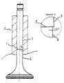
Die erzielbaren Vorteile zeigen sich deutlich an dem erheblich reduzierten Herstellungsaufwand und der damit erst erzielten Wirtschaftlichkeit der Fertigung plasmanitrierter Ventile. Damit ist dieses umweltfreundliche Verfahren auch auf Bimetallventile wirtschaftlich anwendbar. In der Zeichnung ist ein Ausführungsbeispiel eines erfindungsgemäß hergestellten Bimetallventils zusammen mit einer Ausschnittsvergrößerung schematisch dargestellt. Wie bei Bimetallventilen üblich, liegt die Reibschweißnaht 1 mindestens einen halben Ventilhub in der Ventilführung 2. Der Schaftteil 3 oberhalb der Reibschweißnaht übernimmt allein die Führung des Schaftes, da der kopfseitige Schaftteil 4 bei dem gezeigten Beispiel um 0,02 mm durch Schleifen im Durchmesser reduziert ist.The achievable advantages are clearly shown by the considerably reduced manufacturing effort and the economic efficiency of the production of plasma nitrided valves. This environmentally friendly process is therefore also economically applicable to bimetal valves. In the drawing, an embodiment of a bimetal valve manufactured according to the invention is shown schematically together with an enlarged detail. As is usual with bimetallic valves, the friction weld 1 lies at least half a valve stroke in the valve guide 2. The
Claims (6)
Applications Claiming Priority (2)
| Application Number | Priority Date | Filing Date | Title |
|---|---|---|---|
| DE19618477A DE19618477C2 (en) | 1996-05-08 | 1996-05-08 | Manufacturing process for a nitrided bimetal valve |
| DE19618477 | 1996-05-08 |
Publications (3)
| Publication Number | Publication Date |
|---|---|
| EP0806551A2 true EP0806551A2 (en) | 1997-11-12 |
| EP0806551A3 EP0806551A3 (en) | 1998-06-10 |
| EP0806551B1 EP0806551B1 (en) | 2000-06-14 |
Family
ID=7793700
Family Applications (1)
| Application Number | Title | Priority Date | Filing Date |
|---|---|---|---|
| EP97106605A Expired - Lifetime EP0806551B1 (en) | 1996-05-08 | 1997-04-22 | Manufacturing process for nitrided bimetallic valve |
Country Status (2)
| Country | Link |
|---|---|
| EP (1) | EP0806551B1 (en) |
| DE (2) | DE19618477C2 (en) |
Cited By (1)
| Publication number | Priority date | Publication date | Assignee | Title |
|---|---|---|---|---|
| WO2006097264A1 (en) * | 2005-03-18 | 2006-09-21 | Man B & W Diesel Aktiengesellschaft | Gas shuttle valve provided with an anti-corrosive layer |
Families Citing this family (3)
| Publication number | Priority date | Publication date | Assignee | Title |
|---|---|---|---|---|
| DE19812532A1 (en) * | 1998-03-21 | 1999-09-23 | Audi Ag | Connecting rod for a reciprocating machine |
| DE102007026018B4 (en) | 2007-06-04 | 2023-01-19 | Scania Cv Ab | Bimetallic valve with a truncated cone-shaped area of the valve stem |
| DE102008061237A1 (en) * | 2008-12-09 | 2010-06-10 | Man Diesel Se | Gas exchange valve and method for its production |
Citations (1)
| Publication number | Priority date | Publication date | Assignee | Title |
|---|---|---|---|---|
| DE2827271A1 (en) * | 1977-06-22 | 1979-01-18 | Honda Motor Co Ltd | MANUFACTURING PROCESS FOR WELDED VALVE CONES |
Family Cites Families (1)
| Publication number | Priority date | Publication date | Assignee | Title |
|---|---|---|---|---|
| DE4014072A1 (en) * | 1989-06-09 | 1990-12-20 | Thyssen Edelstahlwerke Ag | USE OF ELIGIBLE FERRITIC-PERLITIC (AFP) STEELS AS A MATERIAL FOR GAS EXCHANGE VALVES OF COMBUSTION ENGINES |
-
1996
- 1996-05-08 DE DE19618477A patent/DE19618477C2/en not_active Expired - Fee Related
-
1997
- 1997-04-22 EP EP97106605A patent/EP0806551B1/en not_active Expired - Lifetime
- 1997-04-22 DE DE59701872T patent/DE59701872D1/en not_active Expired - Fee Related
Patent Citations (1)
| Publication number | Priority date | Publication date | Assignee | Title |
|---|---|---|---|---|
| DE2827271A1 (en) * | 1977-06-22 | 1979-01-18 | Honda Motor Co Ltd | MANUFACTURING PROCESS FOR WELDED VALVE CONES |
Non-Patent Citations (1)
| Title |
|---|
| TRW THOMPSON: "Ventile" TRW THOMPSON , September 1986, BARSINGHAUSEN (D), XP002061791 * |
Cited By (1)
| Publication number | Priority date | Publication date | Assignee | Title |
|---|---|---|---|---|
| WO2006097264A1 (en) * | 2005-03-18 | 2006-09-21 | Man B & W Diesel Aktiengesellschaft | Gas shuttle valve provided with an anti-corrosive layer |
Also Published As
| Publication number | Publication date |
|---|---|
| EP0806551B1 (en) | 2000-06-14 |
| EP0806551A3 (en) | 1998-06-10 |
| DE19618477A1 (en) | 1997-12-04 |
| DE59701872D1 (en) | 2000-07-20 |
| DE19618477C2 (en) | 2000-08-03 |
Similar Documents
| Publication | Publication Date | Title |
|---|---|---|
| DE3034519C2 (en) | Metal piston ring | |
| DE3502143C2 (en) | ||
| DE4112576A1 (en) | Piston for diesel engine - is made in two parts which are friction welded together | |
| DE3919199C2 (en) | ||
| DE4200489C2 (en) | Two-part oil ring and process for its manufacture | |
| DE2952290A1 (en) | CAM FOLLOWERS | |
| DE202005008582U1 (en) | Roller chain, e.g. drive chain etc. has pins, sleeves, rollers, and inner and outer plates all of austenitic stainless steel and surface coating formed by nitrifying process | |
| DE2742597B2 (en) | Camshaft for piston engines and work machines, preferably reciprocating internal combustion engines | |
| DE10157968A1 (en) | Split bearing ring and process for its manufacture | |
| EP0806551B1 (en) | Manufacturing process for nitrided bimetallic valve | |
| DE10256689A1 (en) | Link chain used in the automobile industry comprises chain parts connected together via a chain link with a link bolt extending through a link opening to form a chain link | |
| DE2937323A1 (en) | BEARING ELEMENT FOR A JOINT IN TRIPOD DESIGN AND METHOD FOR THE PRODUCTION THEREOF | |
| DE19510302C2 (en) | Surface-treated piston rod and process for its manufacture | |
| EP3473861B1 (en) | Castor wheel and method for manufacturing the same | |
| DE19743627C2 (en) | Method for producing a constriction of the cylinder bore of a cylinder liner | |
| DE4327440A1 (en) | Process for the thermochemical-thermal treatment of hardened steels, heat-treatable steels and bearing steels | |
| WO1998041663A1 (en) | High-performance rolling bearings or rolling components | |
| DE3902518A1 (en) | VALVE SEAL | |
| DE3241712C2 (en) | Camshaft, in particular for the actuation of gas exchange valves on internal combustion engines | |
| DE4218099C2 (en) | ||
| DE4418245C2 (en) | Process for the thermochemical-thermal treatment of a sliding surface of a cam and / or a sliding surface of a cam counter-rotor | |
| DE10311149A1 (en) | Method of manufacturing a forged piston for an internal combustion engine | |
| EP0152587A2 (en) | Mating of material for highly stressed machine-parts | |
| DE2526656A1 (en) | Valve rod for IC engine - has hollow shaft electron welded to base of harder material | |
| DE102004028667A1 (en) | Lever-like cam follower |
Legal Events
| Date | Code | Title | Description |
|---|---|---|---|
| PUAI | Public reference made under article 153(3) epc to a published international application that has entered the european phase |
Free format text: ORIGINAL CODE: 0009012 |
|
| AK | Designated contracting states |
Kind code of ref document: A2 Designated state(s): DE FR GB IT |
|
| AX | Request for extension of the european patent |
Free format text: AL;LT;LV;SI |
|
| RBV | Designated contracting states (corrected) |
Designated state(s): DE FR GB IT |
|
| PUAL | Search report despatched |
Free format text: ORIGINAL CODE: 0009013 |
|
| 17P | Request for examination filed |
Effective date: 19980324 |
|
| AK | Designated contracting states |
Kind code of ref document: A3 Designated state(s): DE FR GB IT |
|
| GRAG | Despatch of communication of intention to grant |
Free format text: ORIGINAL CODE: EPIDOS AGRA |
|
| GRAG | Despatch of communication of intention to grant |
Free format text: ORIGINAL CODE: EPIDOS AGRA |
|
| GRAH | Despatch of communication of intention to grant a patent |
Free format text: ORIGINAL CODE: EPIDOS IGRA |
|
| 17Q | First examination report despatched |
Effective date: 19991116 |
|
| GRAH | Despatch of communication of intention to grant a patent |
Free format text: ORIGINAL CODE: EPIDOS IGRA |
|
| GRAA | (expected) grant |
Free format text: ORIGINAL CODE: 0009210 |
|
| ITF | It: translation for a ep patent filed |
Owner name: DE DOMINICIS & MAYER S.R.L. |
|
| AK | Designated contracting states |
Kind code of ref document: B1 Designated state(s): DE FR GB IT |
|
| GBT | Gb: translation of ep patent filed (gb section 77(6)(a)/1977) |
Effective date: 20000627 |
|
| REF | Corresponds to: |
Ref document number: 59701872 Country of ref document: DE Date of ref document: 20000720 |
|
| ET | Fr: translation filed | ||
| PLBE | No opposition filed within time limit |
Free format text: ORIGINAL CODE: 0009261 |
|
| STAA | Information on the status of an ep patent application or granted ep patent |
Free format text: STATUS: NO OPPOSITION FILED WITHIN TIME LIMIT |
|
| 26N | No opposition filed | ||
| REG | Reference to a national code |
Ref country code: GB Ref legal event code: IF02 |
|
| PGFP | Annual fee paid to national office [announced via postgrant information from national office to epo] |
Ref country code: GB Payment date: 20040312 Year of fee payment: 8 |
|
| PGFP | Annual fee paid to national office [announced via postgrant information from national office to epo] |
Ref country code: FR Payment date: 20040402 Year of fee payment: 8 |
|
| PGFP | Annual fee paid to national office [announced via postgrant information from national office to epo] |
Ref country code: DE Payment date: 20040430 Year of fee payment: 8 |
|
| PG25 | Lapsed in a contracting state [announced via postgrant information from national office to epo] |
Ref country code: IT Free format text: LAPSE BECAUSE OF NON-PAYMENT OF DUE FEES Effective date: 20050422 Ref country code: GB Free format text: LAPSE BECAUSE OF NON-PAYMENT OF DUE FEES Effective date: 20050422 |
|
| PG25 | Lapsed in a contracting state [announced via postgrant information from national office to epo] |
Ref country code: DE Free format text: LAPSE BECAUSE OF NON-PAYMENT OF DUE FEES Effective date: 20051101 |
|
| GBPC | Gb: european patent ceased through non-payment of renewal fee |
Effective date: 20050422 |
|
| PG25 | Lapsed in a contracting state [announced via postgrant information from national office to epo] |
Ref country code: FR Free format text: LAPSE BECAUSE OF NON-PAYMENT OF DUE FEES Effective date: 20051230 |
|
| REG | Reference to a national code |
Ref country code: FR Ref legal event code: ST Effective date: 20051230 |