EP0806528A1 - Fixing device for panels - Google Patents
Fixing device for panels Download PDFInfo
- Publication number
- EP0806528A1 EP0806528A1 EP97201310A EP97201310A EP0806528A1 EP 0806528 A1 EP0806528 A1 EP 0806528A1 EP 97201310 A EP97201310 A EP 97201310A EP 97201310 A EP97201310 A EP 97201310A EP 0806528 A1 EP0806528 A1 EP 0806528A1
- Authority
- EP
- European Patent Office
- Prior art keywords
- accommodation
- fixing device
- resilient
- panels
- panel
- Prior art date
- Legal status (The legal status is an assumption and is not a legal conclusion. Google has not performed a legal analysis and makes no representation as to the accuracy of the status listed.)
- Withdrawn
Links
- 230000004308 accommodation Effects 0.000 claims abstract description 91
- 230000037431 insertion Effects 0.000 claims description 10
- 238000003780 insertion Methods 0.000 claims description 10
- 238000004873 anchoring Methods 0.000 claims description 5
- 239000000853 adhesive Substances 0.000 description 2
- 230000001070 adhesive effect Effects 0.000 description 2
- 230000008878 coupling Effects 0.000 description 1
- 238000010168 coupling process Methods 0.000 description 1
- 238000005859 coupling reaction Methods 0.000 description 1
- 238000001125 extrusion Methods 0.000 description 1
- 238000004519 manufacturing process Methods 0.000 description 1
- 239000000463 material Substances 0.000 description 1
- 239000002184 metal Substances 0.000 description 1
- 238000005192 partition Methods 0.000 description 1
- 239000011505 plaster Substances 0.000 description 1
- 230000008439 repair process Effects 0.000 description 1
- 230000000284 resting effect Effects 0.000 description 1
- 238000005096 rolling process Methods 0.000 description 1
- 239000007787 solid Substances 0.000 description 1
- 239000002023 wood Substances 0.000 description 1
Images


Classifications
-
- E—FIXED CONSTRUCTIONS
- E04—BUILDING
- E04B—GENERAL BUILDING CONSTRUCTIONS; WALLS, e.g. PARTITIONS; ROOFS; FLOORS; CEILINGS; INSULATION OR OTHER PROTECTION OF BUILDINGS
- E04B2/00—Walls, e.g. partitions, for buildings; Wall construction with regard to insulation; Connections specially adapted to walls
- E04B2/74—Removable non-load-bearing partitions; Partitions with a free upper edge
- E04B2/7407—Removable non-load-bearing partitions; Partitions with a free upper edge assembled using frames with infill panels or coverings only; made-up of panels and a support structure incorporating posts
- E04B2/7453—Removable non-load-bearing partitions; Partitions with a free upper edge assembled using frames with infill panels or coverings only; made-up of panels and a support structure incorporating posts with panels and support posts, extending from floor to ceiling
- E04B2/7457—Removable non-load-bearing partitions; Partitions with a free upper edge assembled using frames with infill panels or coverings only; made-up of panels and a support structure incorporating posts with panels and support posts, extending from floor to ceiling with wallboards attached to the outer faces of the posts, parallel to the partition
-
- E—FIXED CONSTRUCTIONS
- E04—BUILDING
- E04B—GENERAL BUILDING CONSTRUCTIONS; WALLS, e.g. PARTITIONS; ROOFS; FLOORS; CEILINGS; INSULATION OR OTHER PROTECTION OF BUILDINGS
- E04B2/00—Walls, e.g. partitions, for buildings; Wall construction with regard to insulation; Connections specially adapted to walls
- E04B2/74—Removable non-load-bearing partitions; Partitions with a free upper edge
- E04B2002/7461—Details of connection of sheet panels to frame or posts
- E04B2002/7462—Details of connection of sheet panels to frame or posts using resilient connectors, e.g. clips
-
- E—FIXED CONSTRUCTIONS
- E04—BUILDING
- E04B—GENERAL BUILDING CONSTRUCTIONS; WALLS, e.g. PARTITIONS; ROOFS; FLOORS; CEILINGS; INSULATION OR OTHER PROTECTION OF BUILDINGS
- E04B2/00—Walls, e.g. partitions, for buildings; Wall construction with regard to insulation; Connections specially adapted to walls
- E04B2/74—Removable non-load-bearing partitions; Partitions with a free upper edge
- E04B2002/7461—Details of connection of sheet panels to frame or posts
- E04B2002/7475—Details of connection of sheet panels to frame or posts using connectors with claws penetrating the sheet panels
Abstract
Description
- The invention relates to a fixing device for panels and to a flat accommodation plate and a resilient lip for use in such a fixing device.
- It is known to fix wall or ceiling panels against the wall or against the ceiling of a structure by screwing the wall panels against fixing sections, or in the case of ceiling panels by supporting them against two T-shaped sections situated opposite each other. In the case of wall panels it was difficult until now to lay these panels in a close-fitting manner against each other, since a fixing space must be left between two adjacent panels. In the case of ceiling panels which are supported on T-shaped support sections, it is possible to place the panels against each other, but the support sections are visible on the outside.
- In the case of the known wall and ceiling sections it is generally difficult to remove a single section for the purpose of carrying out, for example, wiring work or for replacement of a damaged panel. Moreover, the fitting of the known panels is also relatively laborious.
- An object of the present invention is to provide a fixing device by means of which ceiling and wall panels are easy to fix resting against each other on a wall or a ceiling, and in which the panels can easily be removed individually.
- For this purpose, a fixing device according to the invention is characterized in that it comprises a section which is provided with at least one elongated accommodation groove with an insertion face bounded by two front edges situated opposite each other and an accommodation cavity situated behind the insertion face, one dimension of which cavity in an inside face lying parallel to the insertion face is greater than the distance between the front edges, and a resilient clamping element which in a compressed state can pass through the accommodation face and can expand in the accommodation cavity.
- Providing the panels on a rear side with resilient clamping elements which can be pushed into the accommodation groove of the section and subsequently expand in the accommodation cavity means that the panels are easy to fix without tools against the wall or the ceiling. The panels are positioned in a desired position against the sections through the fact that the resilient clamping element becomes engaged behind the edges of the accommodation cavity after expansion. However, if a sufficiently great pulling force is exerted, the resilient fixing elements can be pulled along the edges of the insertion face again until they come out of the accommodation cavity, so that the panel is detached.
- With the present fixing device according to the invention, the panels can be fitted against the specially shaped sections without using tools. Owing to the fact that the resilient clamping elements are situated on the rear side of the panels, the latter can be positioned with their side faces fitting closely against each other, so that unattractive gaps between two adjacent panels are avoided.
- The panels which are connected to a wall or ceiling by means of the fixing device according to the present invention are easy to remove individually therefrom for, for example, repairs or work on parts situated behind the panels, for example wiring or the wall behind.
- It is also possible for the sections according to the present invention to be self-supporting, and not fixed to an already existing wall. This means that a self-supporting structure in which the panels form the walls can be formed.
- One embodiment of a fixing device according to the present invention is characterized in that the clamping element comprises a first, virtually flat accommodation plate which can be fixed against a rear side of a panel and a separate resilient lip which can be inserted by a first end into the accommodation groove and which at another end comprises a body which can be pushed between the accommodation plate and a panel, which body is provided with a resilient locking element which during placing of the body between the panel and the accommodation plate positions the resilient lip by engagement with the accommodation plate. Prior to fitting of the panels against the sections, the flat accommodation plates can be fixed to the rear side of the panels by means of, for example, screws, rivets, adhesive or fixing elements formed on the accommodation plate. The fact that the accommodation plates are a very flat shape means that the panels provided with accommodation plates can still easily be stacked and are consequently easy to transport from the place of manufacture of the panels to the site for fitting. At the place where the wall is to be clad with panels or where the ceiling has been provided with sections according to the invention, the stacked panels can each be provided with one or more individually resilient lips which can be inserted without tools between the accommodation plate and the rear side of the panel. During insertion thereof, the body of the resilient coupling part acts upon the accommodation plate, thereby positioning the resilient lip. The panels, each of which is provided with one or more assembled clamping elements, can then be brought into tight-fitting engagement with the elongated accommodation grooves of the sections.
- The resilient lips preferably comprise a first and a second upright end edge having respectively a concave shape towards the rear side of the body and a convex shape towards the rear side of the body. During insertion into the accommodation groove the end edges act in a tight-fitting manner upon opposite inside walls of the accommodation cavity, so that a secure anchoring is obtained. There are preferably different distances between the upright end edges and a rear wall of the body. A pincer-like fixing element is obtained in a simple manner in this way.
- The accommodation plate is preferably provided on both sides with flat fixing wings, each having sharp, flanged corners for anchoring in the panels. However, it is also possible for the fixing to be by means of adhesives or screws and the like.
- The sections of the fixing device according to the invention preferably comprise two mutually parallel accommodation grooves on one face. In one embodiment of the fixing device according to the invention the section is a hollow section with a substantially rectangular cross-section which is provided with an accommodation groove on at least two mutually perpendicular side faces. In this way two panels can be fixed in a mutually perpendicular position against the section.
- The invention will be explained in greater detail with reference to the appended drawing, in which:
- Figure 1 shows a partially cut-away perspective view of a fixing device according to the present invention;
- Figure 2 shows a top view of a section of the fixing device according to the present invention and two panels fixed thereto by means of a clamping element;
- Figure 3 shows a resilient clamping element for use in a fixing device according to the present invention, comprising a flat accommodation plate and a separate resilient lip; and
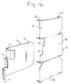
- Figure 4 shows an embodiment in which the resilient lip is provided with a positioning element.
- Figure 1 shows the fixing device 1 according to the present invention with a number of
sections 2, 2' spaced apart. Along the outer periphery the sections are provided withdovetailed accommodation grooves 7, 7' situated in the lengthwise direction. A clamping element 3 is placed at the rear side ofpanels 5, which are formed by, for example, plaster boards, plastic panels or sheets of other suitable materials. The clamping element 3 comprises aflat accommodation plate 13 which can be fixed to the rear side of thepanel 5. Aresilient lip 15 is situated between the rear side of thepanel 5 and theaccommodation plate 13. Afirst end 10 of theresilient lip 15 can be inserted in a tight-fitting manner into theaccommodation groove 7, 7'. - As cam be seen clearly from Figure 2, each accommodation groove comprises two front edges of the type indicated at 9, 9' for accommodation groove 7'. The front edges 9, 9' bound an insertion face by means of which the upright
end edge parts 11, 11' of theresilient lip 15 can be inserted into the accommodation cavity of accommodation groove 7'. The dimensions of the interior of the accommodation groove 7' are greater than the distance between the front edges 9, 9'. This allows the resilientend edge parts 11, 11' of thefirst end 10 of theresilient lip 15 to expand within the accommodation groove 7' and act in a tight-fitting manner on the inside of the accommodation groove. In this case the fact that the front edges 9, 9' are situated relatively close together ensures that the uprightend edge parts 11, 11' in the accommodation groove are prevented from coming out of the accommodation cavity again. Theaccommodation groove 7, 7' can also be a cylindrical shape, instead of dovetailed. - As can be seen from Figure 2, the
accommodation plate 13 is a flat shape and extends at a slight distance from the rear side of thepanel 5, so that thebody 12 of theresilient lip 15 can be pushed underneath theaccommodation plate 13. Situated at the rear side of thebody 12 is alocking element 17 which projects resiliently beyond the face of thebody 12. When the end of thelocking element 17 pushed underneath theaccommodation plate 13 projects beyond the rear side of theaccommodation plate 13, said locking element springs upwards and theresilient lip 15 can no longer move from underneath theaccommodation plate 13. When theresilient lip 15 is being detached, the locking element can be pressed down by hand, and thelip 15 can be pushed forward and out underneath theaccommodation groove 13. - The
accommodation plate 13 comprises a number of flanged corners 21 which can be driven into thepanel 5, so that the accommodation plate is fixed thereto. - The
end edge parts 11 and 11' have curvatures in opposite directions, the end edge part 11' being curved towards the rear side of the body, or being a concave shape, and theend edge part 11 being curved away from the rear side of thebody 12, or being a convex shape. Theend edge parts 11 and 11' are formed by flanged parts of the end edge of theresilient lip 15. As can be seen clearly from Figure 3, the distance of the resilientend edge parts 11, 11'' from the rear edge of thebody 12 differs from that of the central end edge part 11' from said rear edge. Theend edge parts 11, 11'' and 11' each act upon a respective inside wall of theaccommodation groove 7, 7'. - The
accommodation plate 13 comprises twofixing wings 19, 19' and acentral accommodation part 20. Situated along the front edge of thecentral accommodation part 20 is arecess 23 between which the upright end edge part 11' fits when theresilient lip 15 is being inserted. - In the embodiment according to Figure 4 the
body 12 of theresilient lip 15 is provided with a positioning element 11''. The positioning element 11' is formed by flanging the end edge of theresilient lip 15 further at that point. When theend edge parts 11, 11' are being placed in anaccommodation groove 7, 7' of asection 2, 2', the positioning element 11'' rests against the side wall of the section. This ensures that accurate and rapid positioning of theend edge parts 11, 11' in the groove of the section can be obtained. Theaccommodation part 20 is provided along the front edge with a second recess 23' for accommodation of the positioning element 11''. - In the embodiment according to Figure 4 the
fixing wings 19, 19' are provided with flanged, projectingcorner parts 25, 25' for anchoring thereof. Such flanged corner parts ensure that very secure anchoring of theaccommodation plate 13 against a panel is obtained. - The very flat shape of the
accommodation plate 13 means that it can be fixed to thepanels 5 prior to fitting work in whichpanels 5 are fixed to thesections 2, 2'. Thepanels 5 provided with accommodation plates can be stacked and transported in the stacked state to the site where they are to be fixed to a wall or a ceiling. At the site where the panels are to be fixed to the sections, theresilient lips 15 can be connected to theaccommodation plates 13 without tools, in order to complete the clamping elements. The panels provided with clamping elements 3 can then be suspended from the accommodation grooves by hand and without further tools. In this case the panels can be placed in a close-fitting manner against each other with negligible space between them. A seam can be left between the panels if desired. - Although the invention has been described with reference to hollow sections with accommodation grooves situated all the way round, which are formed by, for example, extrusion or preferably by rolling, the
sections 2, 2' can likewise be formed by, for example, flat strips provided with accommodation grooves, or said sections can be solid. Thesections 2, 2' are preferably made of metal, but they can also be made of plastic or wood. The sections can be made up of various separate parts. The sections can be fixed against an unfinished wall or ceiling of a structure, but they can also be placed between the floor and the ceiling, without a further wall being present in order to form, for example, a partition. Moreover, it is equally possible to construct a self-supporting structure by means of the fixing device according to the present invention.
Claims (13)
- Fixing device (1) for panels (5), characterized in that said device comprises a section (2, 2') which is provided with at least one elongated accommodation groove (7, 7') with an insertion face bounded by two front edges (9, 9') situated opposite each other and an accommodation cavity situated behind the insertion face, one dimension of which cavity in an inside face lying parallel to the insertion face is greater than the distance between the front edges (9, 9'), and a resilient clamping element (3) which in a compressed state can pass through the accommodation face and can expand in the accommodation cavity.
- Fixing device (1) according to Claim 1, characterized in that the clamping element (3) comprises a first, virtually flat accommodation plate (13) which can be fixed against a rear side of a panel (5), and a separate resilient lip (15) which can be inserted by a first end (10) into the accommodation groove (7, 7') and which at another end comprises a body (12) which can be pushed between the accommodation plate (13) and a panel (5), which body (12) is provided with a resilient locking element (17) which during placing of the body between the panel and the accommodation plate positions the resilient lip by acting upon the accommodation plate.
- Fixing device (1) according to Claim 2, characterized in that the resilient locking element (17) comprises a tongue which is cut out of the body (12) and projects resiliently beyond the face of the body.
- Fixing device (1) according to Claim 2 or 3, characterized in that the resilient lip (15) comprises at the first end (10) a first (11, 11'') and a second (11') upright end edge part having respectively a concave shape towards the rear side of the body (12) and a convex shape towards the rear side of the body.
- Fixing device (1) according to Claim 4, characterized in that the distances from the upright end edges (11, 11', 11'') to a rear wall of the body (12) differ from each other.
- Fixing device (1) according to Claim 2, characterized in that the accommodation plate (13) is provided with fixing wings (19, 19') on both sides.
- Fixing device (1) according to Claim 6, characterized in that the fixing wings (19, 19') are provided with sharp, flanged corners (21) for anchoring in the panels (5).
- Fixing device (1) according to one of the preceding claims, characterized in that the section (2, 2') is provided with two mutually parallel accommodation grooves (7, 7').
- Fixing device (1) according to one of the preceding claims, characterized in that the section (2, 2') is a hollow section with a substantially rectangular cross-section which is provided with an accommodation groove on at least two mutually perpendicular side faces.
- Fixing device (1) according to one of the preceding claims, characterized in that the resilient lip (15) comprises an upright end edge part (11'') which is situated closer to the rear side of the body (12) of the lip (15) than the other upright end edge parts (11, 11'), thus forming a positioning element.
- Resilient clamping element (3) for use in a fixing device (1) according to one of the preceding claims, characterized in that it comprises a virtually flat accommodation plate (13) which can be fixed against a rear side of a panel, and a separate resilient lip (15) which can be inserted by a first end (10) into the accommodation groove (7, 7') and which at another end comprises a body (12) which can be pushed between the accommodation plate (13) and the panel (5), which body (12) is provided with a resilient locking element (17) which during placing of the body between the panel and the accommodation plate positions the resilient lip (15) by acting upon the accommodation plate.
- Flat accommodation plate (13) for use in a clamping element (3) according to Claim 11, characterized in that the accommodation plate (13) is provided with fixing wings (19, 19') on both sides.
- Resilient lip (15) for use in a clamping element (3) according to Claim 11, characterized in that the lip (15) can be inserted by a first end (10) into the accommodation groove (7, 7') and at another end comprises a body (12) which can be pushed between the accommodation plate (13) and the panel (5), which body (12) is provided with a resilient locking element (17) which during placing of the body (12) between the panel (5) and the accommodation plate (13) positions the resilient lip (15) by acting upon the accommodation plate.
Applications Claiming Priority (2)
| Application Number | Priority Date | Filing Date | Title |
|---|---|---|---|
| NL1003064 | 1996-05-08 | ||
| NL1003064A NL1003064C2 (en) | 1996-05-08 | 1996-05-08 | Fixing device for panels. |
Publications (1)
| Publication Number | Publication Date |
|---|---|
| EP0806528A1 true EP0806528A1 (en) | 1997-11-12 |
Family
ID=19762823
Family Applications (1)
| Application Number | Title | Priority Date | Filing Date |
|---|---|---|---|
| EP97201310A Withdrawn EP0806528A1 (en) | 1996-05-08 | 1997-05-01 | Fixing device for panels |
Country Status (3)
| Country | Link |
|---|---|
| EP (1) | EP0806528A1 (en) |
| CN (1) | CN1165230A (en) |
| NL (1) | NL1003064C2 (en) |
Cited By (5)
| Publication number | Priority date | Publication date | Assignee | Title |
|---|---|---|---|---|
| NL1008261C2 (en) * | 1998-02-10 | 1999-08-11 | Verwol Projektafbouw B V | System wall. |
| WO2003028955A1 (en) * | 2001-09-28 | 2003-04-10 | Louis Roumagere | Improved sandwich panel-type wall construction |
| WO2010089424A1 (en) * | 2009-02-09 | 2010-08-12 | Uralita Iberia S.L. | Construction system for dry partitioning with a ceramic coating |
| WO2017041155A1 (en) * | 2015-09-11 | 2017-03-16 | Bonoli José Luis | Arrangement introduced into a system for fastening dividing panels |
| GB2546477A (en) * | 2016-01-12 | 2017-07-26 | Imagewall Ltd | Exhibition system |
Families Citing this family (4)
| Publication number | Priority date | Publication date | Assignee | Title |
|---|---|---|---|---|
| NL1008084C2 (en) * | 1998-01-21 | 1999-07-22 | Verwol Projektafbouw B V | Sandwich style. |
| FR2924450A1 (en) * | 2007-11-30 | 2009-06-05 | Mecanobloc Soc Par Actions Sim | COMPOSITE POST FOR PARTITION AND PARTIALLY FORMING COMPRISING SUCH A POST |
| US9045910B2 (en) * | 2008-12-15 | 2015-06-02 | The Plasterboard Clip Company Ltd | Clip and method for the mounting of panels |
| CN104235562A (en) * | 2014-08-22 | 2014-12-24 | 山东朗法博粉末涂装科技有限公司 | Artificial board natural environment testing bracket |
Citations (6)
| Publication number | Priority date | Publication date | Assignee | Title |
|---|---|---|---|---|
| CA980973A (en) * | 1973-04-10 | 1976-01-06 | John A. Herwynen | Wall partition system and components therefor |
| US3995402A (en) * | 1975-06-04 | 1976-12-07 | Gerard Parenteau | Panelling assembly for partitions, walls or the like |
| GB2176515A (en) * | 1982-09-07 | 1986-12-31 | Phoenix Interiors Limited | Clips for joining demountable partitioning panels |
| EP0420633A1 (en) * | 1989-09-29 | 1991-04-03 | BPB INDUSTRIES public limited company | Wall construction system |
| US5345739A (en) * | 1993-06-04 | 1994-09-13 | National Gypsum Company | Wallboard attachment |
| US5426904A (en) * | 1994-02-09 | 1995-06-27 | Gilmore; Thomas M. | Partition wall framing assembly for suspending gypsum board panels |
-
1996
- 1996-05-08 NL NL1003064A patent/NL1003064C2/en not_active IP Right Cessation
-
1997
- 1997-05-01 EP EP97201310A patent/EP0806528A1/en not_active Withdrawn
- 1997-05-07 CN CN 97104243 patent/CN1165230A/en active Pending
Patent Citations (6)
| Publication number | Priority date | Publication date | Assignee | Title |
|---|---|---|---|---|
| CA980973A (en) * | 1973-04-10 | 1976-01-06 | John A. Herwynen | Wall partition system and components therefor |
| US3995402A (en) * | 1975-06-04 | 1976-12-07 | Gerard Parenteau | Panelling assembly for partitions, walls or the like |
| GB2176515A (en) * | 1982-09-07 | 1986-12-31 | Phoenix Interiors Limited | Clips for joining demountable partitioning panels |
| EP0420633A1 (en) * | 1989-09-29 | 1991-04-03 | BPB INDUSTRIES public limited company | Wall construction system |
| US5345739A (en) * | 1993-06-04 | 1994-09-13 | National Gypsum Company | Wallboard attachment |
| US5426904A (en) * | 1994-02-09 | 1995-06-27 | Gilmore; Thomas M. | Partition wall framing assembly for suspending gypsum board panels |
Cited By (6)
| Publication number | Priority date | Publication date | Assignee | Title |
|---|---|---|---|---|
| NL1008261C2 (en) * | 1998-02-10 | 1999-08-11 | Verwol Projektafbouw B V | System wall. |
| BE1012758A5 (en) * | 1998-02-10 | 2001-03-06 | Verwol Projektafbouw B V | System wall. |
| WO2003028955A1 (en) * | 2001-09-28 | 2003-04-10 | Louis Roumagere | Improved sandwich panel-type wall construction |
| WO2010089424A1 (en) * | 2009-02-09 | 2010-08-12 | Uralita Iberia S.L. | Construction system for dry partitioning with a ceramic coating |
| WO2017041155A1 (en) * | 2015-09-11 | 2017-03-16 | Bonoli José Luis | Arrangement introduced into a system for fastening dividing panels |
| GB2546477A (en) * | 2016-01-12 | 2017-07-26 | Imagewall Ltd | Exhibition system |
Also Published As
| Publication number | Publication date |
|---|---|
| NL1003064C2 (en) | 1997-05-30 |
| CN1165230A (en) | 1997-11-19 |
Similar Documents
| Publication | Publication Date | Title |
|---|---|---|
| US6430883B1 (en) | Wall system | |
| US5287671A (en) | Construction panel with edges adapted to be coupled together | |
| US7162847B2 (en) | Apparatus and method for fabricating foam wall panels | |
| US4391428A (en) | Lance-type fixture support and method of use | |
| US5114105A (en) | Electrical box support bracket | |
| EP0657060B1 (en) | Apparatus and method for mounting an electrical box between studs in a wall | |
| EP0806528A1 (en) | Fixing device for panels | |
| CN212248998U (en) | Back hanging type wallboard equipment | |
| US9151044B2 (en) | Panel mounting apparatus and related method of manufacture | |
| US4094114A (en) | Detachable wall mounting system | |
| US4494296A (en) | Fixture support installation method | |
| US7971404B2 (en) | Systems and methods for installing panels | |
| US4566241A (en) | Progressive demountable partition | |
| EP0751275A2 (en) | Easily transported and assembled wall structure with sliding door | |
| EP3444410B1 (en) | Bracing panel | |
| AU637479B2 (en) | A connecting device | |
| US4261153A (en) | Accessible-demountable support system for wall paneling and reversible clip means used therein | |
| US4976083A (en) | Panels with laminated strips for clips | |
| CN112534105B (en) | Method for applying a veneer | |
| EP1749950B1 (en) | Fixing device for a panel and kit comprising such fixing device and panel | |
| AU2008201668B2 (en) | Fixing clip | |
| EP3344821B1 (en) | System for wall stud construction | |
| SE458942B (en) | PROCEDURE BEFORE ASSEMBLY OF SELF-SUPPLYING CEILING PANELS | |
| CN211472977U (en) | Assembled bathroom plane wall fixed connection device | |
| CN215211826U (en) | Honeycomb suspended ceiling mounting structure |
Legal Events
| Date | Code | Title | Description |
|---|---|---|---|
| PUAI | Public reference made under article 153(3) epc to a published international application that has entered the european phase |
Free format text: ORIGINAL CODE: 0009012 |
|
| AK | Designated contracting states |
Kind code of ref document: A1 Designated state(s): AT BE CH DE DK ES FI FR GB GR IE IT LI LU NL PT SE |
|
| 17P | Request for examination filed |
Effective date: 19980309 |
|
| 17Q | First examination report despatched |
Effective date: 19991125 |
|
| GRAG | Despatch of communication of intention to grant |
Free format text: ORIGINAL CODE: EPIDOS AGRA |
|
| GRAG | Despatch of communication of intention to grant |
Free format text: ORIGINAL CODE: EPIDOS AGRA |
|
| GRAH | Despatch of communication of intention to grant a patent |
Free format text: ORIGINAL CODE: EPIDOS IGRA |
|
| STAA | Information on the status of an ep patent application or granted ep patent |
Free format text: STATUS: THE APPLICATION IS DEEMED TO BE WITHDRAWN |
|
| 18D | Application deemed to be withdrawn |
Effective date: 20011113 |