EP0806501A2 - Spinning machine with spindle motor control system - Google Patents
Spinning machine with spindle motor control system Download PDFInfo
- Publication number
- EP0806501A2 EP0806501A2 EP97303207A EP97303207A EP0806501A2 EP 0806501 A2 EP0806501 A2 EP 0806501A2 EP 97303207 A EP97303207 A EP 97303207A EP 97303207 A EP97303207 A EP 97303207A EP 0806501 A2 EP0806501 A2 EP 0806501A2
- Authority
- EP
- European Patent Office
- Prior art keywords
- spindle
- phase
- spinning machine
- conductive contacts
- spindle motor
- Prior art date
- Legal status (The legal status is an assumption and is not a legal conclusion. Google has not performed a legal analysis and makes no representation as to the accuracy of the status listed.)
- Withdrawn
Links
- 238000009987 spinning Methods 0.000 title claims abstract description 55
- 230000007246 mechanism Effects 0.000 claims description 48
- 239000000835 fiber Substances 0.000 claims description 23
- 229920003002 synthetic resin Polymers 0.000 claims description 18
- 239000000057 synthetic resin Substances 0.000 claims description 18
- 238000004804 winding Methods 0.000 claims description 17
- 239000000463 material Substances 0.000 claims description 11
- 229920006240 drawn fiber Polymers 0.000 claims description 9
- 239000012209 synthetic fiber Substances 0.000 claims description 9
- 229920002994 synthetic fiber Polymers 0.000 claims description 9
- 239000011810 insulating material Substances 0.000 claims description 5
- 238000004519 manufacturing process Methods 0.000 abstract description 5
- 238000012423 maintenance Methods 0.000 abstract description 4
- 239000000758 substrate Substances 0.000 description 41
- 238000003780 insertion Methods 0.000 description 17
- 230000037431 insertion Effects 0.000 description 17
- 238000007378 ring spinning Methods 0.000 description 16
- RYGMFSIKBFXOCR-UHFFFAOYSA-N Copper Chemical compound [Cu] RYGMFSIKBFXOCR-UHFFFAOYSA-N 0.000 description 8
- 241000237858 Gastropoda Species 0.000 description 8
- 229910052802 copper Inorganic materials 0.000 description 8
- 239000010949 copper Substances 0.000 description 8
- 241001589086 Bellapiscis medius Species 0.000 description 7
- 230000003247 decreasing effect Effects 0.000 description 7
- 230000000694 effects Effects 0.000 description 6
- 238000000034 method Methods 0.000 description 5
- 230000000087 stabilizing effect Effects 0.000 description 4
- 239000011248 coating agent Substances 0.000 description 3
- 238000000576 coating method Methods 0.000 description 3
- 241000234295 Musa Species 0.000 description 2
- 235000018290 Musa x paradisiaca Nutrition 0.000 description 2
- 230000009471 action Effects 0.000 description 2
- 238000010586 diagram Methods 0.000 description 2
- 239000013013 elastic material Substances 0.000 description 2
- 238000010992 reflux Methods 0.000 description 2
- 230000008439 repair process Effects 0.000 description 2
- 230000002411 adverse Effects 0.000 description 1
- 230000008901 benefit Effects 0.000 description 1
- 230000015572 biosynthetic process Effects 0.000 description 1
- 238000005520 cutting process Methods 0.000 description 1
- 238000001514 detection method Methods 0.000 description 1
- 230000005611 electricity Effects 0.000 description 1
- 238000009413 insulation Methods 0.000 description 1
- 239000002184 metal Substances 0.000 description 1
- 229910052751 metal Inorganic materials 0.000 description 1
- 238000000465 moulding Methods 0.000 description 1
- 239000000126 substance Substances 0.000 description 1
Images


Classifications
-
- D—TEXTILES; PAPER
- D01—NATURAL OR MAN-MADE THREADS OR FIBRES; SPINNING
- D01H—SPINNING OR TWISTING
- D01H1/00—Spinning or twisting machines in which the product is wound-up continuously
- D01H1/14—Details
- D01H1/20—Driving or stopping arrangements
- D01H1/24—Driving or stopping arrangements for twisting or spinning arrangements, e.g. spindles
- D01H1/244—Driving or stopping arrangements for twisting or spinning arrangements, e.g. spindles each spindle driven by an electric motor
Definitions
- the present invention relates to a spinning machine having a spindle motor control system (hereinafter, simply referred to as "spinning machine”).
- the present invention more particularly, relates to a spinning machine which at least temporarily stops the rotation of a spindle for drawing long and narrow fibers from a lump of natural fiber or synthetic fiber or raw stock before the formation of fiber (hereinafter, these are referred to as "fiber lump") and twisting the drawn fibers.
- a ring spinning frame as one spinning machine will be described.
- the ring spinning frame is used in the final stage in the spinning process for making yarn from a fiber lump.
- Fig. 26 is an entire perspective view of the spinning frame 1
- Fig. 27 is a view showing a bobbin 9b of a spindle unit 8 and a full bobbin 18
- Fig. 28 is a view of a spindle 9s taken from the above
- Fig. 29 is an enlarged view of main components of a individual stop control unit 13
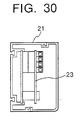
- Fig. 30 is a view taken in the direction of arrows substantially along the line V-V of Fig. 29, Fig.
- FIG. 31 is a view showing a state where the full bobbin 18 is pulled out of the spindle blade 9s
- Fig. 32 is a view showing the full bobbin 18 and the spindle blade 9s covered by the bobbin 9b
- Fig. 33 is a virtual sectional view taken in the direction of arrows substantially along the line VIII-VIII of Fig. 31.
- the ring spinning frame 1 is generally structured as follows. That is, the ring spinning frame 1 mainly comprises a roving unit 3 positioned at the top thereof and having a plurality of rovings 3r as fiber lumps, a draft unit 5 positioned just below the roving unit 3, a snail wire unit (guiding member) 7 for introducing the yarns 6 from the draft unit 5, a spindle unit 8 positioned for winding the yarns 6, introduced by the snail wire unit 7, from the underside, a spindle motor unit (driving member) 11 for driving the spindle unit 8 from the underside, and a individual stop control unit 13 (hereinafter, simply referred to as "control unit”) for individually stopping respective spindle motors.
- control unit for individually stopping respective spindle motors.
- the roving unit 3 is structured as follows. That is, the roving unit 3 comprises a creel C composed of supporting poles arranged in parallel with each other and 6 rovings 3r, 3r,... which are suspended from the creel C. Yarns pulled from the rovings 3r are extended to the draft unit 5 via a guiding rod 14.
- the draft unit 5 comprises a plurality of roller groups 5r, which each comprise a back roller 5r 1 , a middle roller 5r 2 , and a front roller 5r 3
- the surface velocity ratio of the rollers 5r 1 , 5r 2 , 5r 3 is set, for example, to 1:2:20. This allows the roving 3r to be drafted and gives a predetermine size, great strength, and elasticity to the roving 3r.
- the snail wire unit 7 is structured as follows. That is, the snail wire unit 7 comprises spiral-wound wires 7w and a supporting rod 7s onto which the wires 7w are disposed The respective wires 7w are positioned corresponding and just below the respective roller groups 5r. The respective yarns 6 from the draft unit 5 are passed through the respective wires 7w so as to prevent the adjacent yarns from interlocking.
- the spindle unit 8 comprises a plurality of spindles 9.
- Each spindle 9 is structured as follows.
- Each spindle 9 generally comprises a spindle blade 9s as a pole-like rotator (see Fig. 31 and Fig. 33), a bobbin 9b covering the spindle blade 9s and onto which the yarn 6 is wound, a ring-like traveler 15 which slides around the bobbin 9b to twist the yarn 6 delivered from snail wire unit 7, and a ring 17 guiding the traveler 15.
- the traveler 15 is, as shown in Fig. 28, structured as to slide around the bobbin 9b to wind the twisted yarn 6 onto the bobbin 9b.
- the reference numeral 18 designates a full bobbin which is made of yarn wound onto the bobbin 9b.
- Figs. 31 and 32 show the state where the full bobbin 18 is pulled out of the spindle blade 9s and the state where the spindle blade 9s is covered by another bobbin 9b to make another full bobbin 18, respectively.
- the spindle blade 9s is rotatably supported to a bolster 11b (described later) via an insert 9i.
- the insert 9i is disposed to dissipate vibration energy of the spindle blade 9s.
- Disposed around a lower surface of the spindle blade 9s is a rotor 9r corresponding to the spindle motor unit 11.
- the reference numeral 19a designates respective anti-node rings. Each anti-node ring is positioned above the spindle 9 to stabilize the yarn 6.
- the reference numeral 19b designates a ring rail.
- the ring rail 19b is a plate member for supporting the rings 17.
- the ring rail 19b have, in the longitudinal direction, a plurality of through holes (not shown), into which the spindles 9 are inserted, respectively.
- the spindle motor unit 11 comprises, as shown in Figs. 26 and 27, a plurality of spindle motors 12. Tne spindle motors 12 supported by a spindle rail 20 are disposed directly to the spindles 9, respectively. That is, incorporated in each spindle motor 12 is a stator 12s onto which a primary winding is wound in a box-like hollow casing 12c. As stated above, the rotor 9r corresponds to the stator 12s. As shown in Fig. 26, the control unit 13 is actuated by operating each switch 11s so as to stop or restart the corresponding spindle motor 12.
- the control unit 13 is structured as follows. That is, the control unit 13 comprises, as shown in Fig. 29, a duct 21 as a casing having dust-proof and waterproof structure, a plurality of control circuit substrates 23 incorporated in the duct 21, and a plurality of power line substrates 25. Connected to the power line substrates 25 is an output of an inverter power source 26 disposed out of the control unit 13 via a power supply line 32 surfaced by a coating. A low-voltage signal line and low-voltage power supplying line 29 is also connected to the power line substrates 25 to supply low voltage to the control circuit substrates 23. It should be noted that the reference numeral 31 in Fig. 29 designates a power connecting line for connecting the control unit 13 to another control unit 13.
- the operating state of the ring spinning frame will be described according to Figs. 31 through 33.
- the spindle motors 12 are powered and driven by the inverter power source.
- the drive of the spindle motors 12 allow the spindles 19s integrated with the spindle motors 12 to rotate and therefore allow the bobbins 9b to rotate.
- the travelers 15 on the rings 17 are pulled by yarns 6 about to be wound onto the bobbins 9b so as to start to revolve at nearly the same speed as the bobbins 9b (spindles 9s).
- rotational differences between the bobbins 9b (spindles 9s) and the travelers 15 allow the yarns 6 to be wound onto the bobbins 9b.
- the speed of letting off the yarns 6 from the front rollers 5r 3 is the same as the speed of winding the yarns onto the bobbins 9b.
- one twist of the yarn 6 is produced by one revolution of the traveler 15.
- the yarn 6 sometimes snaps during forming the full bobbin 18 between the snail wire unit 7 and the spindle unit 8 or between the draft unit 5 and the snail wire unit 7.
- One cause of yarn snapping is that the rotation of the spindle is unsuitable so that the extra force is exerted onto the yarn 6.
- the aforementioned problems are not limited to the ring spinning frame and are the same for other spinning machines each having a spindle motor control system such as a ring twister and a two-for-one twister.
- the spindle motor 12 To tie the snapped yarn, first the spindle motor 12 must be stopped.
- the spindle motor 12 is stopped by actuating the corresponding switch 11s to separately function the control circuit of the control circuit substrate 23.
- the control circuit substrate 23 must be provided for each spindle motor 12.
- To solve the aforementioned economical problem is the first object to be solved by at least the preferred embodiment of the present invention.
- Some of big spinning frames are 40 meters in overall length. Such a ring spinning frame is provided with about 1000 spindles.
- power is supplied to at control unit 13 of an adjacent mechanical block by an inverter power source 26 through a power connecting line 31.
- low voltage power supply that is, low voltage power or signal is transmitted to control circuit substrates 23 of the control unit 13 through low voltage signal lines/low voltage power supplying lines 29 at a long distance e.g. tens meters. Since using the low voltage signal lines flow voltage power supplying lines renders undesired signal to be easily caught, the operation of circuit quite may become unstable and the control of the whole ring spinning borne may be seriously effected. To eliminate the serious effects is the second object to be solved by at least the preferred embodiment of the present invention.
- the further such object is to increase the efficiency of the power supply, i.e. to inhibit the voltage drop due to electrical resistance of the power supply line 27 and to increase the efficiency of the wiring.
- a housing duct 67 has the power supply line 27 surfaced by a coating and the like incorporated therein.
- the power supply line 27 should be as thick as possible (the cross section should be as greater as possible.).
- there is a limit to make the power supply line 27 thicker because of the size of the housing duct 67. Since it is necessary for the wiring to strip the coating from the power supply line 27, it is not necessarily effective.
- the present invention provides a spinning machine having a spindle motor control system, said machine comprising:
- a spinning machine comprises a plurality of spindles for drawing long and narrow fibers from a lump of natural fiber or synthetic fiber and twisting the drawn fibers; a plurality of spindle motors each provided for each spindle, an inverter power source for supplying power to the spindle motors, and three-phase power supply lines for individually connecting the spindle motors and the inverter power source, and further comprises other member or device as needed.
- the spinning machine is characterized in that each three-phase power supply line is provided with switching mechanisms, for shutting down power, disposed on the ways of at least two phases of the three-phase power supply line, and braking devices each of which brakes each spindle when each switching mechanism is opened.
- the spinning machine having the above features does not have individual control circuits which a conventional spinning machine is provided with. Instead of this, power can be shut down by opening each switching mechanism disposed on the way of each three-phase power supply line and power can be supplied again by closing the switching mechanism. Since even the power is shut down, the spindle motor does not stop soon because of the inertia, the spindle motor is braked or stopped directly or indirectly by the function of the braking device (brake). After the spindle motor stops (decelerates moderately), the snapped yarn may be tied. Because of the operation of the braking device, the snapped yarn can be repaired soon, thereby increasing the efficiency. After the yarn is repaired, the spindle motor is restarted by closing the switching mechanism to supply power.
- the spinning machine can be made at significantly low cost as compared to conventional one, thereby considerably improving the machine because of economic consideration. Further, this structure can omit a long low voltage signal line/low voltage power supplying line and thus avoid adverse effects caused by undesired signal which is indirectly caught by the long low voltage signal line/low voltage power supplying line, thereby stabilizing the operation of the low voltage circuits and thus stabilizing the control of the spinning machine.
- any one having the aforementioned features will do.
- Such a machine includes a two-for-one twister as well as a ring spinning frame and ring twisting frame.
- the "switching mechanism” may be mechanical or electrical one or other one which has efficient functions for supplying and shutting down the power.
- the phrase "at least two phases of the three-phase power supply line” means either two or three phases will do.
- the word “brake” means to restrain the rotation of the spindle (spindle motor) to decelerate or stop the spindle and the “braking device” may be any one having such a braking function.
- braking device are an electrical braking device which brakes the spindle by applying DC voltage to the spindle motor and a mechanical braking device which decelerates and stops the spindle by absorbing kinetic energy for rotating the spindle (spindle motor) by friction.
- the mechanical braking device are a manual brake, a vacuum brake, and an air brake which directly or indirectly provide mechanical friction to the rotating spindle or the like.
- Each switching mechanism may include a pair of conductive contacts which are in electrical contact with each other and an insulating unit which is allowed to be inserted or pulled out between the pair of conductive contacts, wherein the pair of conductive contacts are separated from each other when the insulating unit is inserted therebetween, and come in contact with each other again after the insulating unit is pulled out.
- the switching mechanism only the conductive contacts are separate members and the insulating unit can be used as a common member, thereby simplifying the structure of the switching mechanism and decreasing the cost.
- the "pair of conductive contacts” any one which can be in electrical contact with each other will do, regardless of material and configuration.
- the term “electrical contact” means being in contact to directly or indirectly flow current therebetween.
- the "insulating unit” any one which can separate the pair of conductive contacts when inserted therebetween and can allow the pair of conductive contacts to come in contact with each other after pulled out will do.
- Such an insulating unit includes one having insulation performance of itself such as synthetic resin plate and one having conductive performance but having any structure for shutting down current.
- each switching mechanism may include a pair of conductive contacts and a switching member slidably disposed between the pair of conductive contacts, wherein said switching member is provided with an insulating portion and a conductive portion which are selectively brought into contact with said pair of conductive contacts by sliding the switching member.
- the switching mechanism only by sliding the switching mechanism i.e. moving the switching member without pulling out, the conductive contacts in contact with the insulating portion (not conducted) can be brought in contact with the conductive portion to conduct electricity between the conductive contacts and vice versa.
- the switching member may be configured not to be pulled out between the conductive contacts, it is preferable that it is configured to be pulled out. If the switching member is configured to be pulled out, the switching member can be used as a common member, as aforementioned, thereby simplifying the structure of the switching mechanism and decreasing the cost In this case, it is preferable that the pair of conductive contacts are in electrical contact with each other when the switching member is pulled out.
- each switching mechanism may include a pair of conductive contacts spaced from each other and a connecting member for electrically connecting the pair of conductive contacts when closed.
- the conductive contacts and the connecting member may be formed in any configurations which sufficiently function for the purposes.
- the connecting member may be detachable or not.
- each braking device is characterized by including a frictional member moveable to contact the spindle, a brake arm to which said frictional member is fixed, an operational lever for bringing the brake arm close to or away from the spindle, a supporting member for pivotaly supporting the operational lever, and biasing means for biasing the brake arm in such a direction as to move from the spindle.
- the mechanical braking device may be of a type that is mounted to each spindle or of a removable type that is mounted to any one of spindles as needed. Though at least one frictional member and one brake arm are enough, it is preferable to push the spindle in the opposite directions at the same time (toward the axis of the spindle). The reason is that since the gap between the stator and the rotor of the spindle motor is quite small, the spindle swings so that the stator and the rotor come in contact with each other when the frictional member is pushed to the spindle in one direction.
- three frictional members may be disposed 120° apart from each other and structured to push the spindle at the same time (toward the axis of the spindle).
- the operational direction of the operational lever may be the vertical direction, the horizontal direction, or other direction.
- the braking device may include a brake voltage supplying device for applying braking DC voltage to the spindle motor.
- this electrical braking device supplies the braking voltage sufficient to brake the spindle and may be individually mounted to each spindle, or may be detachable so that the electrical braking device can be attached to any spindle as needed. It should be understood that the braking voltage is sufficient to brake the spindle.
- the DC voltage applied by a braking voltage supplying device may be produced by rectifying three phases or any two phases of the three-phase power supply line, i.e. by rectifying AC voltage obtained from the inverter power source as the driving power supply of the spindle motors.
- the DC voltage may be obtained in this manner so that another power source for the braking voltage is no longer necessary, thereby reducing the entire cost of manufacturing the spinning machine.
- each switching mechanism may correspond to the braking or release of the braking device.
- the braking device can be actuated by opening the switching mechanism and, conversely, the braking device can be released by closing the switching mechanism.
- One action renders a plurality of actions, thereby simplifying the operation and allowing another operation such as repairing of snapped yarn to be rapidly and efficiently done.
- Designers can determine which operation of the switching mechanism or the braking device is the main according to his/her idea and the structure of the switching mechanism (the braking device). How they are coupled (correspond) to each other may use any method considered by persons skilled in the art.
- stator windings of each spindle motor are fixed by fitting synthetic resin materials around the stator windings, and the synthetic resin materials are formed in such a manner that each switching mechanism is partially or entirely fitted to the synthetic resin.
- the synthetic resin allows the configuration to be designed with relatively wide flexibility to fit the configurations of the stator windings and the switching mechanism and can easily insulate the stator windings from the switching mechanism and other components.
- the phrase "the switching mechanism is partially or entirely fitted" includes a case where the switching mechanism has a single component and a case where the switching mechanism has a plurality of components. In the latter case, the part or the entire of the switching mechanism means (a portion or the entire of) one or some of the components or (or a portion or the entire of) all of the components. Any fitting method can be employed.
- the present invention provides a spinning machine comprising a plurality of spindles for drawing long and narrow fibers from a mass of natural fiber or synthetic fiber and twisting the drawn fibers;
- the spinning machines comprises plurality of spindles for drawing long and narrow fibers from a lump of natural fiber or synthetic fiber and twisting the drawn fibers; a plurality of spindle motors each provided for each spindle, an inverter power source for supplying power to said spindle motors, and three-phase power supply lines for individually connecting said spindle motors and said inverter power source, wherein each three-phase power supply line is provided with a pair of conductive contacts electrically connected to at least two phases on the way thereof a pair of conductive contacts are structured to allow a circuit unit to be inserted and pulled out therebetween.
- the circuit unit has a DC braking mode and at least one of three modes: a three-phase power shutdown mode, three-phase power supplying mode, and a Reduced DC braking mode set therein, any one of the DC braking mode and the set mode(s) can be selected by operating a control switch. That is, the circuit unit can select at least one of the three modes besides the DC braking mode as necessary.
- the circuit unit is inserted between the pair of conductive contacts to separate the pair of conductive contacts so as to be actuated, while the circuit unit is pulled out to bring the pair of conductive contacts into contact with again.
- To select at least one of the three modes means to select one mode (for example, three-phase power shutdown mode) set in the circuit unit, or to select as needed one of two (for example, three-phase power shutdown mode and the three-phase power supplying mode) or three modes set in the circuit unit.
- one mode for example, three-phase power shutdown mode
- two modes for example, three-phase power shutdown mode and the three-phase power supplying mode
- three modes set in the circuit unit.
- the two modes are set, either the DC braking mode, three-phase power shutdown mode, or the three-phase power supplying mode is selected.
- another mode than the three modes is set.
- the circuit unit stops the spindle motor by applying DC voltage, obtained from the braking voltage supplying device, to the spindle motor.
- the circuit unit shuts down three-phase AC power to the spindle motor.
- the circuit unit supplies three-phase AC power to the spindle.
- the circuit unit applies DC voltage, obtained from the braking voltage supplying device, to the spindle motor to prevent the stopped spindle from rotating involuntarily.
- the aforementioned “circuit unit” may be formed to match with the configuration of the pair of conductive contacts or the like.
- the “braking voltage supplying device” may be any one which can supply DC voltage needed for stopping the spindle motor to the degree which allow the yarn to be repaired.
- involuntary rotation means the passive rotation of the spindle motor because of external force exerted on the spindle motor, not the active rotation of the spindle motor because of power supplied to the spindle motor. Since a snapped yarn is repaired by twisting (rotating) the yarns, the spindle motor involuntarily rotates due to the external force produced at this time. As the spindle motor involuntarily rotates, it is difficult to twist the yarn.
- subdued DC voltage lower than the braking DC voltage is applied to the spindle motor. Since the circuit unit operates only when inserted between the conductive contacts, three-phase AC is applied to the spindle after pulling out the circuit unit.
- the braking voltage supplying device may produce the DC voltage and subdued DC voltage by rectifying three phases or any two phases of each three-phase power supply line.
- the DC voltage can be obtained by a simple circuit, thereby improving the cost effectiveness. Also it allows the circuit unit to be miniaturised and light weight so that it is convenient when the circuit is carried in a spinning factory.
- the spinning machine may further include a relay unit for electrically relaying the circuit unit and the pair of conductive contacts.
- the relay unit is structured, instead of the circuit unit, to be inserted and pulled out between the pair of conductive contacts. Moreover, the relay unit allows the circuit unit to be inserted and pulled out therebetween. In addition, the relay unit functions as an insulating unit for insulating the pair of conductive contacts when the relay unit is inserted alone.
- the main feature of this spinning machine is that the contact between the circuit unit and the conductive contacts are carried out via the relay unit not by directly inserting (connecting) the circuit unit between the conductive circuits.
- the relay unit functions as an insulating unit so as to shut down the power to the spindle motor.
- the reason why the relay unit is provided is that the relay unit is convenient in particular when the spindle motor is still desired to be stopped even after pulling out the circuit unit for some reasons. Since the conductive contacts are insulated even after pulling out the circuit unit, the spindle motor still stops.
- the relay unit can be used as the insulating unit as aforementioned.
- each spindle motor may be fixed by filling synthetic resin materials around the stator windings, and the synthetic resin materials are formed in such a manner that each switching mechanism is partially or entirely fitted to the synthetic resin.
- any method which allows the conductive contacts to be fitted without losing the functions thereof may be employed.
- each of them comprises bare three-phase buses, i.e. three-phase buses which is not covered, connected to the inverter power source and distributing lines connecting the three-phase buses and each spindle motor, and the three-phase buses are embedded in a casing made of insulating material and partly exposed from the casing. Therefore, the efficiency of the power supply can be increased and the efficiency of the wiring can be increased. That is, for example, non-covered bare copper bars (copper poles) are embedded in a casing formed by molding synthetic resin as insulated material and are used as the three-phase buses. In this case, the synthetic resin inserted between the copper bars functions as covers (insulating member) so that it is not necessary to cover the three-phase buses.
- the copper bars i.e. three-phase buses can be thicker (increased in sections) because of the covers which is no longer needed.
- the three-phase buses may be other conductive members instead of the copper bars.
- the exposed face of each copper bar may be formed in any configuration which allows the wiring.
- each three-phase bus is formed in plane.
- the exposed face of each three-phase bus is formed in plane because the contact resistance can be reduced by increasing the cross sections of the three-phase bus and another conductive member (copper bar) to be connected to the three-phase bus. It is also preferable for mounting solterless terminals because the plane face facilitates the mounting.
- each three-phase bus exposed from the casing is provided with a detachable terminal for allowing each distributing line to be attached or detached to the three-phase bus.
- a detachable terminal allows the distributing line to be attached or detached, thereby increasing efficiency of the wiring. If necessary, other wire besides the distributing line may be connected.
- This "detachable terminal” may be of a screw type or a jack type. An example of such a type is a banana jack (banana plug) formed in a banana-like shape.
- a spinning machine comprises a plurality of spindles for drawing long and narrow fibers from a mass of natural fiber or synthetic fiber and twisting the drawn fibers; a plurality of spindle motors each provided for a respective spindle, an inverter power source for supplying power to the spindle motors, and three-phase power supply lines for individually connecting the spindle motors and the inverter power source, and is characterized in that each three-phase power supply line comprises bare three-phase buses connected to the inverter power source and distributing lines connecting the three-phase buses and each spindle motor. At least the bare three-phase buses being disposed in a casing at predetermined spaces, thereby increasing the sections of the bare three-phase buses because of no covering.
- the spinning machine may further comprise insulating material between said bare three-phase buses. This structure increases the insulative property between the bare three-phase buses, thereby increasing the electrical safety of the spinning machine.
- each spindle motor 12A designates each spindle motor.
- Each spindle motor 12A is in a hollow casing 12c.
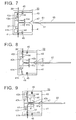
- the hollow casing 12c is provided with an insertion portion 33 into which a circuit substrate unit (circuit unit) 49 can be inserted.
- a three-phase power supply line 35 for carrying power to the spindle motor 12A is inserted into each insertion portion 33.
- the three-phase power supply line 35 is cut at a relay 35p to which a pair of conductive contacts 37, 39 are connected.
- the conductive contact 37 and the other conductive contact 39 are brought into contact with each other to flow current
- the conductive contact 37 is connected to the inverter power source 26 (Fig.
- the combination of the conductive contacts 37, 29 and the circuit unit 49 compose a switching mechanism for shutting down the power. It is preferable to combine the switching mechanism and a braking device as described below.
- the conductive contact 37 is made by forming a high conductive metal piece into a hook-like configuration and is fitted to a mounting groove 41c formed in the supporting member 41.
- a stopper 44 is formed by cutting a portion of the conductive contact 37 and standing the cut portion diagonally backward. The stopper 44 is hooked on an engaging hole 41h formed in the supporting member 41. Therefore, a conductive contact 37 is prevented from coming off the supporting member 41.
- the reference numeral 45 designates each spring for pushing the supporting member in the direction toward the inside of the insertion portion 33 (upwardly in this drawing).
- the distance between the supporting members 41 and 43 pushed by the springs 45, 45 is elastically increased and decreased.
- the conductive contact 37 may be formed of high elastic material to also have a function of the spring 45. Between the facing surfaces is fanned out toward the front to have an opening 47.
- the conductive contacts 37 and 39 are separated by inserting a circuit unit 49 (described later) through the opening and the conductive contacts 37 and 39 come into contact with each other again because of the function of the springs 45, 45 by pulling out the circuit unit 49.
- the circuit unit 49 has one end 49e which is recessed and fixed to the insertion portion 33.
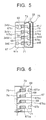
- the circuit unit 49 comprises a casing member 51 of which both ends are opened, a slidable member 53 which is mounted inside the casing member 51 at the front end 5 le in such a manner that the slidable member is capable of sliding in the longitudinal direction, a circuit substrate 55 mounted to the center of the slidable member 53, and a control switch 59 mounted on the circuit substrate.
- the control switch 59 is connected to the circuit substrate 55 by a connecting line 60.
- a cable extension may be disposed between the circuit unit 49 and the insertion portion 33 and have a connector disposed at the end thereof to insert the connector into the insertion.
- the operation of the circuit unit 49 can be controlled remotely from the insertion portion 33.
- the circuit substrate 55 is provided with a control circuit 57 in which a DC braking mode and a three-phase power shutdown mode, a three-phase power supplying mode, or a subdued DC braking mode are set. Other modes than these modes may be set as needed. The switching among these modes is performed by operating the control switch 59.
- the DC braking mode is set to brake or stop the spindle motor 12A by applying DC voltage, produced by rectifying three phases (or any two phases) of each three-phase power supply line 35U, 35V, 35W, to the spindle motor 12A.
- the three-phase power shutdown mode is set to shut down the three-phase AC power to each spindle motor 12A, 12A,....
- the three-phase power supplying mode is set to supply the three-phase AC power to each spindle motor 12A, 12A,....
- the subdued DC braking mode is set to apply DC feeble voltage, produced by rectifying the three phases or any two phases of each three-phase power supply line 35U, 35V, 35W, to the spindle motor 12A to prevent the spindle from rotating involuntarily.
- the reason for providing the three-phase power shutdown mode in this embodiment is that a main switch of the inverter power source 26 does not have to be turned off when the power supply to the spindle motors should be shut down for some reason.
- the reason for providing the three-phase power supplying mode is, for example, that it is convenience for checking the tied yarn to rotate temporarily the spindle motor.
- the spindle motor 12A is rotated just by pulling out the circuit unit 49 from the insertion portion 33. However, there is a case that the spindle motor has to be stopped soon by inserting the circuit unit 49 due to faulty tying. It is troublesome to pull out and insert the circuit unit many times. In such a case, the three-phase power shutdown mode is used to temporarily rotate the spindle motor, thereby solving such trouble.
- the reason for providing the subdued DC braking mode is to efficiently tie a snapped yarn as mentioned above.
- the tip 55e of the circuit substrate 55 has conducting parts 61, 61 on the both surfaces thereof, respectively as shown in Fig. 7, which come into contact with the conductive contacts 37, 39, respectively (Figs. 8 and 9).
- the conducting parts 61, 61 allow the control circuit 57 to be energized.
- the circuit substrate 55 has a rectifier circuit for rectifying any two phases of the three-phase power supply line 35 and a power circuit 65 having a DC-DC converter circuit, which are incorporated in the circuit substrate 55.
- a power circuit 63 is provided to supply DC voltage for energizing the spindle motor 12A when the DC braking mode or the subdued DC braking mode is selected. instead of the power circuit 63, a battery or an external power source may be employed.
- the tip 55e Upon inserting the aforementioned circuit unit 49 i.e. the circuit substrate 55 into the insertion portion 33 as shown in Figs. 7 through 9, the tip 55e separates the supporting members 41, 43 (conductive contacts 37, 39) against the biasing forces of the springs 45, 45 so as to shut down the supply of power from the inverter power source 26 to the spindle motor 12A.
- the supporting members 41, 43 conductive contacts 37, 39
- the supporting members 41, 43 conductive contacts 37, 39
- Figs. 21 through 22 Shown in Figs. 21 through 22 is an alternative of the circuit unit 49 composing a part of the switching mechanism.
- the reference numeral 49a in Fig. 21 designates an insulating unit made of synthetic resin. By inserting the insulating unit 49a between the conductive contacts 37 and 39, the conductive contacts 37 and 39 are separated from each other to shut down the power (Fig. 21 (a)), while by pulling out the insulating unit 49a, the conductive contacts 37 and 39 are brought in contact with each other to restart supply of power (Fig. 21 (b)).
- the reference numeral 49b designates a switching member which is provided with a metallic terminal (conductive portion) disposed on one end of the insulating unit 49a to conduct the front and the back of the insulating unit 49a.
- the metallic terminal 49d and the other portion (insulating portion 49c) are selectively brought in contact with the conductive contacts 37, 39 by sliding the switching member between the conductive contacts 37 and 39. That is, power is supplied when the metallic terminal 49d is in contact with the conductive contacts 37, 39 and power is shut down when the insulating portion 49c is in contact with the conductive contacts 37, 39.
- the switching member 49b is allowed to be pulled out between the conductive contacts 37 and 39 and the conductive contacts 37 and 39 are in electrical contact with each other when the switching member 49b is pulled out.
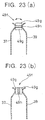
- the switching mechanism shown in Fig. 23 generally comprises the pair of conductive contacts 37, 39 and a rotary switching member 49f disposed between the conductive contacts 37 and 39.
- a rotary switching member 49f By rotating the rotary switching member 49f in the direction of the arrow shown in Fig. 23, insulating portions 49g, 49g and a conductive portion 49h can be selectively brought in contact with the conductive contacts 37, 39.
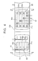
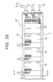
- the control unit 13A has a housing duct (casing) 67 and three-phase buses (copper bars) 69 which are embedded in the housing duct 67.
- the three-phase buses 69 forms a part of the three-phase power supply line 35.
- the housing duct 67 is made of insulating material such as plastic and comprises a substrate 67, a patch 73, and a cover 75.
- the substrate 67 has 4 parallel and straight grooves 67b 1 through 67b 4 , into which the buses 69 are embedded, formed in the longitudinal direction thereof.
- the buses 69 and an earth 71 are embedded in the grooves 67b 1 through 67b 4 and are covered by the patch 73.
- the patch 73 is covered by the cover 75.
- the configurations of the grooves 67b 1 through 67b 4 may be devised to prevent the three-phase buses 69 and the earth 71 from coming off so that the patch 73 may be omitted.
- the buses 69 and the earth 71 have respective parts facing (exposed) outside the housing duct 67.
- the spindle motor 12A is energized by wires 74 fixed to the exposed faces 69o and 71o.
- a series of housing ducts are formed, by connecting several housing ducts each of which is connected to two spindles 9, 9, for every fixed number of spindles (herein 24 spindles) wherein the fixed number is suited for the configuration of the ring spinning frame 1A.
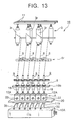
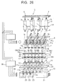
- a control circuit 57 shown in Fig. 11 is a circuit for applying DC voltage, produced by rectifying the half waves of and controlling three-phase AC phases supplied from the three-phase power supply line 35, to the spindle motor 12A.
- the control circuit 57 is structured as follows. That is, the control circuit 57 comprises a main element circuit 57A performing switching, rectification, and phase control for the three-phase power source, a phase control (ignition control) circuit 57B performing phase and ignition control of each thyristor, and a phase detection circuit 57C used for the phase control.
- thyristors are used in the main element circuit 57A.
- the supply and shutdown of the three-phase power source are performed by bi-directional thyristors THU1, THV1, and THW1.
- the three-phase half-wave rectification for producing DC voltage is performed by THU2, THV3, THW1, and THV2.
- the phase control for varying the value of DC voltage is performed by THU2 and THV3.
- the reference numeral D1 designates a reflux diode for carrying reflux current.
- the main element circuit 57A shown in Fig. 12 (1) is in the condition that the three-phase power supplying mode is selected.
- power is supplied to the control circuit 57 through bus-side contact pieces 37U, 37V, 37W and contact pieces 61U, 61V, 61W which are in contact with 37U, 37V, 37W, respectively.
- gate signals 57a and 57b are turned on so that the bi-directional thyristors THU1, THV1 and THW1 serially connected to the three phases U, V and W, respectively are turned on.
- the three-phase voltage inputted in this manner is outputted through the bus-side contact pieces 37U, 37V and 37W.
- the main element circuit 57 shown in Fig. 12 (2) is in the condition that the three-phase power shutdown mode is selected.
- the bi-directional thyristors THU1, THV1 and TRW1 are turned off so that the gate signals 57a and 57b are turned on, the inputted three-phase voltage is not outputted to the contact pieces 37U, 37V and 37W.
- the thyristor THV2 for rectifier control may be ON or OFF.
- the main element circuit 57A shown in Fig. 12 (3) shows is the case that the DC braking mode is selected.
- the gate signal 57, THU1 and THV1 are OFF.
- the gate signals 57b, 57c, 57e, and 57a are turned on so as to turn on THV2 for rectifier control, THU2 and THV3 for phase control, thereby forming the three-phase half-wave rectification circuit comprising V phase, U phase and W phase.
- the spindle motor is braked using DC voltage outputted by the three-phase half-wave rectification circuit.
- the ignition phase of the thyristor THV3 for phase control, the value of DC voltage applied to the spindle motor is decreased, with the result that the braking force is subdued (subdued DC braking mode).
- the ignition phase is controlled in such a manner that the DC voltage becomes to the degree to which the spindle motor is prevented from rotating involuntarily. As the voltage is too low, the involuntary rotation of the spindle during the repair working for a snapped yarn interferes the repair working so that it does not go just as you want.
- the switching (selection) of the aforementioned modes is performed by operating the mode control switch 59 (see Fig. 3) mounted on the circuit substrate 55 as mentioned above.
- the mode switch is made up of a single switch in this embodiment, the modes may be switched by a plurality of switches or may be automatically switched from one mode to anther mode after elapse of fixed time period, using a timer incorporated therein.
- the other modes than the DC braking mode may be omitted so that the control circuit may comprise only the DC braking mode and any one of the other modes.
- the control circuit may comprise two modes: the DC braking mode and the subdued DC braking mode it necessary (the three-phase power shutdown mode and the three-phase power supplying mode are omitted), or may comprise three modes: the above modes and the three-phase power supplying mode (the three-phase power shutdown mode is omitted). That is, the DC braking mode is necessary and one of the other modes as needed is enough.
- the reference numeral 1B designates a ring twisting frame as one of spinning machine.
- the basic differences between the ring twisting frame 1B and the ring spining flame 1A are that the latter does not include the draft unit 5 and that the latter is provided with rollers 5r for drawing the yarns 6 from the rovings 3, respectively.
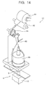
- the reference numeral 1C designates a two-for-one twister 1C as one of spinning machine. Also in the two-for-one twister 1C, the same technique as the ring spinning frame 1A and the ring twisting frame 1B is employed basically.
- spindle motors 12 for rotating spindles 9 as components are controlled by a spindle motor control system A. As shown in Fig. 14, fiber is wound onto a yarn supply package 88 via a winding package 80, a winding drum 82, rollers as a feed roller 84, and a balloon guide. Consequently, there is no difference between the effects given by the two-for-one twister 1C and that of the ring spinning frame 1A.
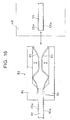
- the fourth embodiment With reference to Fig. 15 (1) and (2), the fourth embodiment will be described.
- the difference between the fourth embodiment and the first embodiment is that the fourth embodiment has a relay unit which the first embodiment does not have.
- the description will be made as regard only to the relay unit 80 and the description about other members will be omitted.
- the relay unit 80 is provided to be inserted between the circuit unit 49 and the insertion portion 33 to relay the function of the circuit unit 49.
- the main advantage of providing the relay unit 80 is that the spindle motor 12 can be stopped without inserting the circuit unit 49 as mentioned above.
- the relay unit 80 is structured as follows. That is, the relay unit 80 comprises a hollow casing 81, a relay substrate 82 incorporated in the hollow casing 81, and a relay connector mounted on the rear end of the relay substrate 82.
- the hollow casing 81 is configured to be bigger than the circuit unit 49 so as to allow the circuit unit 49 to be inserted into the hollow casing 81.
- the front end of the relay substrate is structured to be inserted between the supporting members 41, 43 (conductive contacts 37, 39), like the tip 55e of the circuit substrate 55.
- the open end of the relay connector 83 is structured to allow the circuit substrate 55 of the circuit unit 49 to be inserted into the open end, like the supporting members 41, 43.
- the relay connector 83 has a pair of supporting parts 84, 84 and a pair of conductive contacts 85, 85 caught between the supporting parts 84, 84.
- the relay substrate 82 is fixed by inserting the relay substrate 82 from one side (left side in the drawing) into the relay connector 83.
- the conductive contacts 85, 85 are brought in electrical contact with the conductive faces 82a, 82a of the relay substrate 82 so as to come into indirect contact with the conductive contacts 37, 39 of the insertion portion 33, respectively.
- the conductive contacts 85, 85 are formed by high elastic material so as to elastically deform as shown by the arrows when the circuit-substrate 55 of the circuit unit 49 is inserted thereto and pulled off therefrom and to come in electrical contact with conductive faces 55a, 55a. This allows the electrical contact between the circuit substrate 55 and the conductive contacts 37, 39 of the insertion portion 33 to control (brake) the spindle motor 12A.
- the open ends of the conductive contacts 85, 85 in the state where the circuit substrate 55 is not inserted are separated from each other and are not in electrical contact with each other as shown in Fig. 16. Therefore, upon inserting the relay unit 83 in this state, the conductive contacts 37, 39 of the insertion portion 33 are separated from each other to shut down the power to the spindle motor 12A.
- the relay unit 83 functions as an insulating unit for shutting down the power. In case of using the relay unit 83 as the insulating unit, the relay unit 83 is inserted alone to shut down the power and the involuntary stopping of the spindle motor 12A is waited to tie the yarn 6.
- the alternative is characterized by comprising a cable extension 88 electrically connected to the circuit unit 49 (circuit substrate 55) and a connector 89 connected to the open end of the cable extension 88.
- the cable extension 88 and the connector 89 allow the spindle motor 12A to be controlled remotely from the insertion portion 33.
- the circuit unit 49 of the alternative preferably comprises a closed casing instead of a hollow casing. This prevents accidents such as short of the circuit substrate 55 due to dusts or an alien substance.
- any external appearance which can allow sufficient electrical contact with the conductive contacts 85, 85 and allow the connector to be inserted and pulled out is enough.
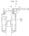
- the reference numeral 100 designates a braking device mounted on each spindle motor 12.
- the braking device 100 generally comprises following members. That is, the braking device 100 generally comprises a operational lever 101 which is pushed down by a hand of an operator, a supporting member 102 supporting the operational lever 101 to allow the operational lever 101 to move up and down, a projection 103 projecting from a lower surface of the operational lever 101, and two brake arms 110, 111.
- An end 103a of the projection 103 is configured in a gentle conical shape so that when pushing down the operational lever 101, the end of the projection 103 comes in contact with cam faces 111, 113 (described later) of the brake arms 110, 112 to widen a space therebetween.
- the spindle is caught by the brake arms 110, 112.
- the braking device 100 is structured in such a manner that, as needed, the spindle blade is applied with equal braking forces from the both side, that is, toward the axis.
- the brake arms 110, 112 are each formed in S-like configuration as shown in Fig. 18.
- the brake arms 110, 112 have ends 110a, 112a which are rotatably secured to a pivot axis 114 and guide holes 116, 117 formed on the way thereof through which a movable shaft 115 is passed so that the brake arms 110, 112 is movable along the guide holes 116, 117.
- Fixed on the upper end of the movable shall 115 is the supporting member 102.
- the brake arms 110, 112 are provided with the aforementioned tapered cam faces 111, 113, respectively, at the open ends 110b, 112b.
- the brake arms 110, 112 are provided with friction pieces 118, 118 mounted on the inner peripheries and coil springs 119, 119 mounted on the external peripheries thereof to exert forces in such a direction that the brake arm 110 and the brake arm 112 are separated.
- the spring forces of the coil springs 119, 119 are exerted on the cam face 111 and cam face 113 in such a direction of pulling each other.
- the operation of the fifth embodiment is as follows.
- the operational lever 101 becomes in a state as shown by virtual lines in Fig. 17 because of the function of the supporting member 102.
- the end of the projection comes in contact with the cam faces 111,113.
- the state in which the end is in contact with the cam faces 111, 113 is shown by solid lines in Fig. 19.
- the state in which the operational lever is further pushed down is shown by virtual lines in Fig. 19.
- any one capable of biasing the brake arms 110 and 112 in the widening direction is enough.
- the friction pieces 118 and the brake arms 110, 112 have elastic structures, these function as biasing means.
- the frictional pieces 118 deform when coming in contact with the spindle and elastically return to increase the spacing between the brake arms 110, 112 when exerted with no external force for braking.
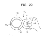
- Fig. 20 shows the sixth embodiment.
- the sixth embodiment may exhibit basically the same effect as the fifth embodiment.
- the fifth embodiment is characterized in that the braking of the spindle blade is performed by grasping handles 111, 111 of the braking device which is configured like a pair of pliers, while the braking is performed by pushing down the operational lever in the fifth embodiment.
- the coil springs 119 function as biasing means.
- the coil springs 119 may be eliminated and the friction pieces 118 may be used as the biasing means.
- Fig. 24 shows the combinaion of the switching mechanism shown in Fig. 22 and the mechanical braking device shown in Fig. 17. To avoid the repetition, like parts are given by like reference numerals so as to omit the description about the parts.
- the switching member 49f is fixed to the lower end of the central portion of the operational lever 101 and the switching member 49b is structured so as to slide between the conductive contacts 37 and 39 when the operational lever 101 is moved to pivot about the supporting member 102.
- the insulating portion 49c of the switching member 49f is in contact with the conductive contacts 37, 39 so that the switching mechanism is opened when the operational lever 101 is pulled upward, and the conductive portion 49d is in contact with the conductive contacts 37, 39 so that the switching mechanism is closed when the operational lever 101 is pushed downward.
- the projection 103 operates the brake arms 112 to brake the spindle 9s corresponding to the upward movement of the operational lever 101, and releases the braking corresponding the downward movement of the operational lever 101.
- the reference numeral 150 in Fig. 24 designates covering members made of synthetic resin fixing the stator windings (shown by dotted lines) of the spindle motor.
- the covering members 150 are formed in such a manner that the switching member is fitted to the covering members 150 without losing the functions of the motor casing.
- the configuration of the covering members 150 is formed to fit the configurations of the switching member and the like.
- a pair of conductive contacts 37a, 39a separated from each other as shown in Fig. 25 may be employed.
- the conduction between the conductive contacts 37a and 39a is performed by pushing the operational lever 101 downward against the spring force of a spring 101b to bring a conductive connecting member 101a in contact with terminals of the conductive contacts 37a and 39a.
- the operational lever 101 is released, the operational lever 101 is pushed upward by the spring force of the spring, the connecting member 101a is not in contact with them and, corresponding to this, the projection 103 operates the brake arms 112.
- the spinning machine as described above exhibits the following effects.
- each three-phase power supply line is provided with a pair of conductive contacts electrically connected to at least two phases on the way thereof, and the pair of conductive contacts are structured to be separated when inserting in insulating unit therebetween and to come in contact with each other again when pulling out the insulating unit.
Landscapes
- Engineering & Computer Science (AREA)
- Mechanical Engineering (AREA)
- Textile Engineering (AREA)
- Spinning Or Twisting Of Yarns (AREA)
Abstract
Description
- The present invention relates to a spinning machine having a spindle motor control system (hereinafter, simply referred to as "spinning machine"). The present invention, more particularly, relates to a spinning machine which at least temporarily stops the rotation of a spindle for drawing long and narrow fibers from a lump of natural fiber or synthetic fiber or raw stock before the formation of fiber (hereinafter, these are referred to as "fiber lump") and twisting the drawn fibers.
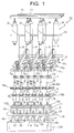
- Referring to Figs. 26 through 33, a ring spinning frame as one spinning machine will be described. The ring spinning frame is used in the final stage in the spinning process for making yarn from a fiber lump. Fig. 26 is an entire perspective view of the spinning
frame 1, Fig. 27 is a view showing abobbin 9b of aspindle unit 8 and afull bobbin 18, Fig. 28 is a view of aspindle 9s taken from the above, Fig. 29 is an enlarged view of main components of a individualstop control unit 13, Fig. 30 is a view taken in the direction of arrows substantially along the line V-V of Fig. 29, Fig. 31 is a view showing a state where thefull bobbin 18 is pulled out of thespindle blade 9s, Fig. 32 is a view showing thefull bobbin 18 and thespindle blade 9s covered by thebobbin 9b, and Fig. 33 is a virtual sectional view taken in the direction of arrows substantially along the line VIII-VIII of Fig. 31. - As shown in Fig. 26, the ring spinning
frame 1 is generally structured as follows. That is, thering spinning frame 1 mainly comprises aroving unit 3 positioned at the top thereof and having a plurality ofrovings 3r as fiber lumps, adraft unit 5 positioned just below theroving unit 3, a snail wire unit (guiding member) 7 for introducing theyarns 6 from thedraft unit 5, aspindle unit 8 positioned for winding theyarns 6, introduced by thesnail wire unit 7, from the underside, a spindle motor unit (driving member) 11 for driving thespindle unit 8 from the underside, and a individual stop control unit 13 (hereinafter, simply referred to as "control unit") for individually stopping respective spindle motors. It should be understood that the number of members are the same to correspond to each other unless description will be specifically made because all of the number of therovings 3r, the number of components of thedraft unit 5, and the number of components of thesnail wire unit 7 are the same (6 in this example). - The
roving unit 3 is structured as follows. That is, theroving unit 3 comprises a creel C composed of supporting poles arranged in parallel with each other and 6rovings rovings 3r are extended to thedraft unit 5 via a guiding rod 14. Thedraft unit 5 comprises a plurality ofroller groups 5r, which each comprise aback roller 5r1, amiddle roller 5r2, and afront roller 5r3 The surface velocity ratio of therollers - The
snail wire unit 7 is structured as follows. That is, thesnail wire unit 7 comprises spiral-wound wires 7w and a supportingrod 7s onto which thewires 7w are disposed Therespective wires 7w are positioned corresponding and just below therespective roller groups 5r. Therespective yarns 6 from thedraft unit 5 are passed through therespective wires 7w so as to prevent the adjacent yarns from interlocking. - The
spindle unit 8 comprises a plurality ofspindles 9. Eachspindle 9 is structured as follows. Eachspindle 9 generally comprises aspindle blade 9s as a pole-like rotator (see Fig. 31 and Fig. 33), abobbin 9b covering thespindle blade 9s and onto which theyarn 6 is wound, a ring-like traveler 15 which slides around thebobbin 9b to twist theyarn 6 delivered fromsnail wire unit 7, and aring 17 guiding thetraveler 15. Thetraveler 15 is, as shown in Fig. 28, structured as to slide around thebobbin 9b to wind thetwisted yarn 6 onto thebobbin 9b. In Figs. 27 and 28, thereference numeral 18 designates a full bobbin which is made of yarn wound onto thebobbin 9b. Figs. 31 and 32 show the state where thefull bobbin 18 is pulled out of thespindle blade 9s and the state where thespindle blade 9s is covered by anotherbobbin 9b to make anotherfull bobbin 18, respectively. - It should be noted that the
spindle blade 9s is rotatably supported to abolster 11b (described later) via aninsert 9i. Theinsert 9i is disposed to dissipate vibration energy of thespindle blade 9s. Disposed around a lower surface of thespindle blade 9s is arotor 9r corresponding to thespindle motor unit 11. - In Fig. 26, the
reference numeral 19a designates respective anti-node rings. Each anti-node ring is positioned above thespindle 9 to stabilize theyarn 6. Thereference numeral 19b designates a ring rail. Thering rail 19b is a plate member for supporting therings 17. Thering rail 19b have, in the longitudinal direction, a plurality of through holes (not shown), into which thespindles 9 are inserted, respectively. - The
spindle motor unit 11 comprises, as shown in Figs. 26 and 27, a plurality ofspindle motors 12.Tne spindle motors 12 supported by aspindle rail 20 are disposed directly to thespindles 9, respectively. That is, incorporated in eachspindle motor 12 is astator 12s onto which a primary winding is wound in a box-likehollow casing 12c. As stated above, therotor 9r corresponds to thestator 12s. As shown in Fig. 26, thecontrol unit 13 is actuated by operating eachswitch 11s so as to stop or restart thecorresponding spindle motor 12. - The
control unit 13 is structured as follows. That is, thecontrol unit 13 comprises, as shown in Fig. 29, aduct 21 as a casing having dust-proof and waterproof structure, a plurality ofcontrol circuit substrates 23 incorporated in theduct 21, and a plurality ofpower line substrates 25. Connected to thepower line substrates 25 is an output of an inverter power source 26 disposed out of thecontrol unit 13 via a power supply line 32 surfaced by a coating. A low-voltage signal line and low-voltagepower supplying line 29 is also connected to thepower line substrates 25 to supply low voltage to thecontrol circuit substrates 23. It should be noted that thereference numeral 31 in Fig. 29 designates a power connecting line for connecting thecontrol unit 13 to anothercontrol unit 13. - The operating state of the ring spinning frame will be described according to Figs. 31 through 33. The
spindle motors 12 are powered and driven by the inverter power source. The drive of thespindle motors 12 allow the spindles 19s integrated with thespindle motors 12 to rotate and therefore allow thebobbins 9b to rotate. Thetravelers 15 on therings 17 are pulled byyarns 6 about to be wound onto thebobbins 9b so as to start to revolve at nearly the same speed as thebobbins 9b (spindles 9s). At this time, rotational differences between thebobbins 9b (spindles 9s) and thetravelers 15 allow theyarns 6 to be wound onto thebobbins 9b. The speed of letting off theyarns 6 from thefront rollers 5r3 is the same as the speed of winding the yarns onto thebobbins 9b. In addition, one twist of theyarn 6 is produced by one revolution of thetraveler 15. - By the way, as shown in Figs. 31 and 32, the
yarn 6 sometimes snaps during forming thefull bobbin 18 between thesnail wire unit 7 and thespindle unit 8 or between thedraft unit 5 and thesnail wire unit 7. One cause of yarn snapping is that the rotation of the spindle is unsuitable so that the extra force is exerted onto theyarn 6. The aforementioned problems are not limited to the ring spinning frame and are the same for other spinning machines each having a spindle motor control system such as a ring twister and a two-for-one twister. - To tie the snapped yarn, first the
spindle motor 12 must be stopped. Thespindle motor 12 is stopped by actuating thecorresponding switch 11s to separately function the control circuit of thecontrol circuit substrate 23. Thecontrol circuit substrate 23 must be provided for eachspindle motor 12. There are some big spinning frame each having substantially 1000 spindle motors. In this case, substantially 1000 control circuit substrates are necessary. However, it is impossible that all of 1000 yarns snap at the same time so that there may be no situation that the all of the control circuit substrates are needed at the same time. It is quite poor economy to always prepare many control circuit substrates, though nobody knows when they will be actually needed, in view points of manufacturing expenses and maintenance / checkout expenses. To solve the aforementioned economical problem is the first object to be solved by at least the preferred embodiment of the present invention. - Some of big spinning frames are 40 meters in overall length. Such a ring spinning frame is provided with about 1000 spindles. In such a spinning frame, power is supplied to at
control unit 13 of an adjacent mechanical block by an inverter power source 26 through apower connecting line 31. The same is true for low voltage power supply, that is, low voltage power or signal is transmitted to controlcircuit substrates 23 of thecontrol unit 13 through low voltage signal lines/low voltagepower supplying lines 29 at a long distance e.g. tens meters. Since using the low voltage signal lines flow voltage power supplying lines renders undesired signal to be easily caught, the operation of circuit quite may become unstable and the control of the whole ring spinning borne may be seriously effected. To eliminate the serious effects is the second object to be solved by at least the preferred embodiment of the present invention. - The further such object is to increase the efficiency of the power supply, i.e. to inhibit the voltage drop due to electrical resistance of the
power supply line 27 and to increase the efficiency of the wiring. That is, ahousing duct 67 has thepower supply line 27 surfaced by a coating and the like incorporated therein. To minimize the electrical resistance, thepower supply line 27 should be as thick as possible (the cross section should be as greater as possible.). However, there is a limit to make thepower supply line 27 thicker because of the size of thehousing duct 67. Since it is necessary for the wiring to strip the coating from thepower supply line 27, it is not necessarily effective. - In a first aspect, the present invention provides a spinning machine having a spindle motor control system, said machine comprising:
- a plurality of spindle motors, each provided for a respective spindle,
- an inverter power source for supplying power to said spindle motors, and three-phase power supply lines for individually connecting said spindle motors and said inverter power source, wherein the spindle motor control system comprises switching mechanisms, for shutting down power, disposed along the paths of at least two phases of the three phase power supply line, and braking devices each of which brakes a respective spindle when a respective switching mechanism is operated.
- In a preferred embodiment, a spinning machine comprises a plurality of spindles for drawing long and narrow fibers from a lump of natural fiber or synthetic fiber and twisting the drawn fibers; a plurality of spindle motors each provided for each spindle, an inverter power source for supplying power to the spindle motors, and three-phase power supply lines for individually connecting the spindle motors and the inverter power source, and further comprises other member or device as needed. The spinning machine is characterized in that each three-phase power supply line is provided with switching mechanisms, for shutting down power, disposed on the ways of at least two phases of the three-phase power supply line, and braking devices each of which brakes each spindle when each switching mechanism is opened.
- The spinning machine having the above features does not have individual control circuits which a conventional spinning machine is provided with. Instead of this, power can be shut down by opening each switching mechanism disposed on the way of each three-phase power supply line and power can be supplied again by closing the switching mechanism. Since even the power is shut down, the spindle motor does not stop soon because of the inertia, the spindle motor is braked or stopped directly or indirectly by the function of the braking device (brake). After the spindle motor stops (decelerates moderately), the snapped yarn may be tied. Because of the operation of the braking device, the snapped yarn can be repaired soon, thereby increasing the efficiency. After the yarn is repaired, the spindle motor is restarted by closing the switching mechanism to supply power. According to this structure, the spinning machine can be made at significantly low cost as compared to conventional one, thereby considerably improving the machine because of economic consideration. Further, this structure can omit a long low voltage signal line/low voltage power supplying line and thus avoid adverse effects caused by undesired signal which is indirectly caught by the long low voltage signal line/low voltage power supplying line, thereby stabilizing the operation of the low voltage circuits and thus stabilizing the control of the spinning machine.
- As for the "spinning machine" described in this specification, any one having the aforementioned features will do. Such a machine includes a two-for-one twister as well as a ring spinning frame and ring twisting frame. In addition, the "switching mechanism" may be mechanical or electrical one or other one which has efficient functions for supplying and shutting down the power. The phrase "at least two phases of the three-phase power supply line" means either two or three phases will do.
- It should be noted that the word "brake" means to restrain the rotation of the spindle (spindle motor) to decelerate or stop the spindle and the "braking device" may be any one having such a braking function. Examples of braking device are an electrical braking device which brakes the spindle by applying DC voltage to the spindle motor and a mechanical braking device which decelerates and stops the spindle by absorbing kinetic energy for rotating the spindle (spindle motor) by friction. Examples of the mechanical braking device are a manual brake, a vacuum brake, and an air brake which directly or indirectly provide mechanical friction to the rotating spindle or the like.
- Each switching mechanism may include a pair of conductive contacts which are in electrical contact with each other and an insulating unit which is allowed to be inserted or pulled out between the pair of conductive contacts, wherein the pair of conductive contacts are separated from each other when the insulating unit is inserted therebetween, and come in contact with each other again after the insulating unit is pulled out.
- According to the switching mechanism, only the conductive contacts are separate members and the insulating unit can be used as a common member, thereby simplifying the structure of the switching mechanism and decreasing the cost. As for the "pair of conductive contacts", any one which can be in electrical contact with each other will do, regardless of material and configuration. In addition, the term "electrical contact" means being in contact to directly or indirectly flow current therebetween. As for the "insulating unit", any one which can separate the pair of conductive contacts when inserted therebetween and can allow the pair of conductive contacts to come in contact with each other after pulled out will do. Such an insulating unit includes one having insulation performance of itself such as synthetic resin plate and one having conductive performance but having any structure for shutting down current.
- Alternatively, each switching mechanism may include a pair of conductive contacts and a switching member slidably disposed between the pair of conductive contacts, wherein said switching member is provided with an insulating portion and a conductive portion which are selectively brought into contact with said pair of conductive contacts by sliding the switching member.
- According to this switching mechanism, only by sliding the switching mechanism i.e. moving the switching member without pulling out, the conductive contacts in contact with the insulating portion (not conducted) can be brought in contact with the conductive portion to conduct electricity between the conductive contacts and vice versa. Though the switching member may be configured not to be pulled out between the conductive contacts, it is preferable that it is configured to be pulled out. If the switching member is configured to be pulled out, the switching member can be used as a common member, as aforementioned, thereby simplifying the structure of the switching mechanism and decreasing the cost In this case, it is preferable that the pair of conductive contacts are in electrical contact with each other when the switching member is pulled out.
- As another alternative, each switching mechanism may include a pair of conductive contacts spaced from each other and a connecting member for electrically connecting the pair of conductive contacts when closed.
- The conductive contacts and the connecting member may be formed in any configurations which sufficiently function for the purposes. The connecting member may be detachable or not.
- Preferably, each braking device is characterized by including a frictional member moveable to contact the spindle, a brake arm to which said frictional member is fixed, an operational lever for bringing the brake arm close to or away from the spindle, a supporting member for pivotaly supporting the operational lever, and biasing means for biasing the brake arm in such a direction as to move from the spindle.
- The mechanical braking device may be of a type that is mounted to each spindle or of a removable type that is mounted to any one of spindles as needed. Though at least one frictional member and one brake arm are enough, it is preferable to push the spindle in the opposite directions at the same time (toward the axis of the spindle). The reason is that since the gap between the stator and the rotor of the spindle motor is quite small, the spindle swings so that the stator and the rotor come in contact with each other when the frictional member is pushed to the spindle in one direction. It possible in view of cost and structure, three frictional members may be disposed 120° apart from each other and structured to push the spindle at the same time (toward the axis of the spindle). The operational direction of the operational lever may be the vertical direction, the horizontal direction, or other direction.
- The braking device may include a brake voltage supplying device for applying braking DC voltage to the spindle motor.
- It should be understood that this electrical braking device supplies the braking voltage sufficient to brake the spindle and may be individually mounted to each spindle, or may be detachable so that the electrical braking device can be attached to any spindle as needed. It should be understood that the braking voltage is sufficient to brake the spindle.
- The DC voltage applied by a braking voltage supplying device may be produced by rectifying three phases or any two phases of the three-phase power supply line, i.e. by rectifying AC voltage obtained from the inverter power source as the driving power supply of the spindle motors.
- The DC voltage may be obtained in this manner so that another power source for the braking voltage is no longer necessary, thereby reducing the entire cost of manufacturing the spinning machine.
- The operation of each switching mechanism may correspond to the braking or release of the braking device.
- These are coupled to each other so that the braking device can be actuated by opening the switching mechanism and, conversely, the braking device can be released by closing the switching mechanism. One action renders a plurality of actions, thereby simplifying the operation and allowing another operation such as repairing of snapped yarn to be rapidly and efficiently done. Designers can determine which operation of the switching mechanism or the braking device is the main according to his/her idea and the structure of the switching mechanism (the braking device). How they are coupled (correspond) to each other may use any method considered by persons skilled in the art.
- Preferably, the stator windings of each spindle motor are fixed by fitting synthetic resin materials around the stator windings, and the synthetic resin materials are formed in such a manner that each switching mechanism is partially or entirely fitted to the synthetic resin.
- Such a structure mentioned above can omit a motor casing which is usually used for protecting the stator windings, thereby avoiding troubles in assembling them and decreasing the cost. The reason for using the synthetic resin is that the synthetic resin allows the configuration to be designed with relatively wide flexibility to fit the configurations of the stator windings and the switching mechanism and can easily insulate the stator windings from the switching mechanism and other components. It should be noted that the phrase "the switching mechanism is partially or entirely fitted" includes a case where the switching mechanism has a single component and a case where the switching mechanism has a plurality of components. In the latter case, the part or the entire of the switching mechanism means (a portion or the entire of) one or some of the components or (or a portion or the entire of) all of the components. Any fitting method can be employed.
- In a second embodiment, the present invention provides a spinning machine comprising a plurality of spindles for drawing long and narrow fibers from a mass of natural fiber or synthetic fiber and twisting the drawn fibers;
- a plurality of spindle motors each provided for a respective spindle,
- an inverter power source for supplying power to said spindle motors, and
- three-phase power supply lines for individually connecting said spindle motors and said inverter power source, wherein
- each three-phase power supply line is provided with a pair of conductive contacts electrically connected to at least two phases along the path thereof,
- said pair of conductive contacts are structured to allow a circuit unit to be removably inserted therebetween to operate the contacts and actuate the circuit unit;
- said circuit unit has a DC braking mode and at least one of a three-phase power shutdown mode, a three-phase power supplying mode, and a subdued DC braking mode set therein, the DC braking mode or one of the other modes being selectable by operation of a control switch; wherein the circuit unit is adapted to brake each spindle motor by applying DC voltage produced by an external or internal braking voltage supplying device to the spindle motor when the DC braking mode is selected;
- to shut down three-phase AC power to the spindle motor when the three-phase power shutdown mode is selected;
- to supply three-phase AC power to the spindle when the three-phase power supplying mode is selected; and
- to apply subdued DC voltage, produced by said braking voltage supplying device, to the spindle motor to prevent the stopped spindle from rotating involuntarily when the subdued DC braking mode is selected.
- In a preferred embodiment, the spinning machines comprises plurality of spindles for drawing long and narrow fibers from a lump of natural fiber or synthetic fiber and twisting the drawn fibers; a plurality of spindle motors each provided for each spindle, an inverter power source for supplying power to said spindle motors, and three-phase power supply lines for individually connecting said spindle motors and said inverter power source, wherein each three-phase power supply line is provided with a pair of conductive contacts electrically connected to at least two phases on the way thereof a pair of conductive contacts are structured to allow a circuit unit to be inserted and pulled out therebetween.
- The circuit unit has a DC braking mode and at least one of three modes: a three-phase power shutdown mode, three-phase power supplying mode, and a Reduced DC braking mode set therein, any one of the DC braking mode and the set mode(s) can be selected by operating a control switch. That is, the circuit unit can select at least one of the three modes besides the DC braking mode as necessary. The circuit unit is inserted between the pair of conductive contacts to separate the pair of conductive contacts so as to be actuated, while the circuit unit is pulled out to bring the pair of conductive contacts into contact with again.
- To select at least one of the three modes means to select one mode (for example, three-phase power shutdown mode) set in the circuit unit, or to select as needed one of two (for example, three-phase power shutdown mode and the three-phase power supplying mode) or three modes set in the circuit unit. In the former case, only the three-phase power shutdown mode is set (selected) and thus either the DC braking mode or three-phase power shutdown mode is selected. On the other hand, in the latter case where the two modes are set, either the DC braking mode, three-phase power shutdown mode, or the three-phase power supplying mode is selected. The same is true for a case where another mode than the three modes is set.
- Hereinafter, the details of the modes set in the circuit unit are as follows. When the DC braking mode is selected, the circuit unit stops the spindle motor by applying DC voltage, obtained from the braking voltage supplying device, to the spindle motor. When the three-phase power shutdown mode is selected, the circuit unit shuts down three-phase AC power to the spindle motor. When the three-phase power supplying mode is selected, the circuit unit supplies three-phase AC power to the spindle. Further, when the Reduced DC braking mode is selected, the circuit unit applies DC voltage, obtained from the braking voltage supplying device, to the spindle motor to prevent the stopped spindle from rotating involuntarily.
- The aforementioned "circuit unit" may be formed to match with the configuration of the pair of conductive contacts or the like. The "braking voltage supplying device" may be any one which can supply DC voltage needed for stopping the spindle motor to the degree which allow the yarn to be repaired. In addition, the term "involuntary rotation" means the passive rotation of the spindle motor because of external force exerted on the spindle motor, not the active rotation of the spindle motor because of power supplied to the spindle motor. Since a snapped yarn is repaired by twisting (rotating) the yarns, the spindle motor involuntarily rotates due to the external force produced at this time. As the spindle motor involuntarily rotates, it is difficult to twist the yarn. To prevent the involuntary rotation, subdued DC voltage lower than the braking DC voltage is applied to the spindle motor. Since the circuit unit operates only when inserted between the conductive contacts, three-phase AC is applied to the spindle after pulling out the circuit unit.
- The braking voltage supplying device may produce the DC voltage and subdued DC voltage by rectifying three phases or any two phases of each three-phase power supply line.
- In the structure as mentioned above, the DC voltage can be obtained by a simple circuit, thereby improving the cost effectiveness. Also it allows the circuit unit to be miniaturised and light weight so that it is convenient when the circuit is carried in a spinning factory.
- The spinning machine may further include a relay unit for electrically relaying the circuit unit and the pair of conductive contacts. The relay unit is structured, instead of the circuit unit, to be inserted and pulled out between the pair of conductive contacts. Moreover, the relay unit allows the circuit unit to be inserted and pulled out therebetween. In addition, the relay unit functions as an insulating unit for insulating the pair of conductive contacts when the relay unit is inserted alone.
- The main feature of this spinning machine is that the contact between the circuit unit and the conductive contacts are carried out via the relay unit not by directly inserting (connecting) the circuit unit between the conductive circuits. When the circuit unit is pulled out the relay unit inserted between the conductive contacts or the relay unit is inserted between the conductive contact alone, the relay unit functions as an insulating unit so as to shut down the power to the spindle motor. The reason why the relay unit is provided is that the relay unit is convenient in particular when the spindle motor is still desired to be stopped even after pulling out the circuit unit for some reasons. Since the conductive contacts are insulated even after pulling out the circuit unit, the spindle motor still stops. As the relay unit is inserted alone, the relay unit can be used as the insulating unit as aforementioned.
- The stator windings of each spindle motor may be fixed by filling synthetic resin materials around the stator windings, and the synthetic resin materials are formed in such a manner that each switching mechanism is partially or entirely fitted to the synthetic resin.
- As the method of fitting the pair of conductive contacts, any method which allows the conductive contacts to be fitted without losing the functions thereof may be employed. In addition, there is no limitation with reference to the direction in which the conductive contacts are fitted.
- The present invention also extends to a spinning machine comprises a plurality of spindles for drawing long and narrow fibers from a mass of natural fiber or synthetic fiber and twisting the drawn fibers; a plurality of spindle motors each provided for a respective spindle, an inverter power source for supplying power to the spindle motors, and three-phase power supply for individually connecting the spindle motors and the inverter power source, and is characterized by the three-phase power supply lines.
- The features of the three-phase power supply lines are that each of them comprises bare three-phase buses, i.e. three-phase buses which is not covered, connected to the inverter power source and distributing lines connecting the three-phase buses and each spindle motor, and the three-phase buses are embedded in a casing made of insulating material and partly exposed from the casing. Therefore, the efficiency of the power supply can be increased and the efficiency of the wiring can be increased. That is, for example, non-covered bare copper bars (copper poles) are embedded in a casing formed by molding synthetic resin as insulated material and are used as the three-phase buses. In this case, the synthetic resin inserted between the copper bars functions as covers (insulating member) so that it is not necessary to cover the three-phase buses. The copper bars i.e. three-phase buses can be thicker (increased in sections) because of the covers which is no longer needed. The three-phase buses may be other conductive members instead of the copper bars. The exposed face of each copper bar may be formed in any configuration which allows the wiring.
- Preferably, at least the exposed part of each three-phase bus is formed in plane. Though there is no limitation for the configuration of the exposed face as mentioned above, it is preferable that the exposed face of each three-phase bus is formed in plane because the contact resistance can be reduced by increasing the cross sections of the three-phase bus and another conductive member (copper bar) to be connected to the three-phase bus. It is also preferable for mounting solterless terminals because the plane face facilitates the mounting.
- Preferably, each three-phase bus exposed from the casing is provided with a detachable terminal for allowing each distributing line to be attached or detached to the three-phase bus. Such a detachable terminal allows the distributing line to be attached or detached, thereby increasing efficiency of the wiring. If necessary, other wire besides the distributing line may be connected. This "detachable terminal" may be of a screw type or a jack type. An example of such a type is a banana jack (banana plug) formed in a banana-like shape.
- In a fourth aspect, a spinning machine comprises a plurality of spindles for drawing long and narrow fibers from a mass of natural fiber or synthetic fiber and twisting the drawn fibers; a plurality of spindle motors each provided for a respective spindle, an inverter power source for supplying power to the spindle motors, and three-phase power supply lines for individually connecting the spindle motors and the inverter power source, and is characterized in that each three-phase power supply line comprises bare three-phase buses connected to the inverter power source and distributing lines connecting the three-phase buses and each spindle motor. At least the bare three-phase buses being disposed in a casing at predetermined spaces, thereby increasing the sections of the bare three-phase buses because of no covering.
- The spinning machine may further comprise insulating material between said bare three-phase buses. This structure increases the insulative property between the bare three-phase buses, thereby increasing the electrical safety of the spinning machine.
- Preferred features of the present invention will now be described, by way of example only, with reference to the accompanying drawings, in which:-
- Fig. 1 is an entire perspective view of a ring spinning frame as the first embodiment;
- Fig. 2 is a vertical sectional view of a spindle and a spindle motor;
- Fig. 3 is an enlarged view of the main parts shown in Fig. 2;
- Fig. 4 is a partly enlarged view of a control unit;
- Fig. 5 is a view taken in the direction of arrows substantially along the line X-X of Fig. 4;
- Fig. 6 is a view taken in the direction of arrow substantially along the line IV-IV of Fig. 4;
- Fig. 7 is a view showing a state just before the circuit substrate is inserted between the contacts;
- Fig. 8 is a view showing a state where the circuit substrate is just inserted therebetween;
- Fig. 9 is a view showing a state where the insertion is finished;
- Fig. 10 is a view showing a state where conductive contacts are incorporated into supporting members;
- Fig. 11 is a circuit diagram for rectifying three phases of a three-phase power supplier;
- Fig. 12 is circuit diagrams showing mode states, respectively;
- Fig. 13 is a schematic view showing the second embodiment;
- Fig. 14 is a schematic view showing the third embodiment;
- Fig. 15 is schematic views showing the fourth embodiment;
- Fig. 16 is a partly enlarged view of a relay connector;
- Fig. 17 is a schematic view showing the fifth embodiment;
- Fig. 18 is a front view of Fig. 17;
- Fig. 19 is a view taken in the direction of arrow substantially along the line Y-Y of Fig. 18;
- Fig. 20 is a schematic view of the sixth embodiment;
- Fig. 21 is a plan view showing the schematic structure of a switching mechanism;
- Fig. 22 is a plan view showing the schematic structure of a switching mechanism;
- Fig. 23 is a plan view showing the schematic structure of a switching mechanism;
- Fig. 24 is a schematic sectional view showing the seventh embodiment;
- Fig. 25 is a schematic sectional view showing the seventh embodiment;
- Fig. 26 is an entire perspective view showing an example of conventional ring spinning frame;
- Fig. 27 is a view showing a bobbin of a spindle unit and a full bobbin;
- Fig. 28 is a view of a spindle taken from the above;
- Fig. 29 is an enlarged view of main components of a individual
stop control unit 13; - Fig. 30 is a view taken in the direction of arrows substantially along the line V-V of Fig. 29;
- Fig. 31 is a view showing a state where the full bobbin is pulled out of the spindle blade;
- Fig. 32 is a view showing the
full bobbin 18 and the spindle blade covered by a bobbin; and - Fig. 33 is a virtual sectional view taken in the direction of arrows substantially along the line VIII-VIII of Fig. 31.
- In the following description, parts similar to those described with reference to Figures 26 to 33 are given the same reference numerals.
- In Figs. 1 and 2, the
reference numeral 12A designates each spindle motor. Eachspindle motor 12A is in ahollow casing 12c. Thehollow casing 12c is provided with aninsertion portion 33 into which a circuit substrate unit (circuit unit) 49 can be inserted. As shown in Figs. 2 and 3, a three-phasepower supply line 35 for carrying power to thespindle motor 12A is inserted into eachinsertion portion 33. The three-phasepower supply line 35 is cut at arelay 35p to which a pair ofconductive contacts conductive contact 37 and the otherconductive contact 39 are brought into contact with each other to flow current Theconductive contact 37 is connected to the inverter power source 26 (Fig. 26) and theconductive contact 39 is connected to thespindle motor 12A. In this embodiment, the combination of theconductive contacts circuit unit 49 compose a switching mechanism for shutting down the power. It is preferable to combine the switching mechanism and a braking device as described below. - With reference to Figs. 7 through 10, description is made of the conductive 37, 39 and supporting
members conductive contact 39 is the same as theconductive contact 37 and the supportingmember 43 is the same as the supportingmember 41, the description will be made as regard only to the respective former and the description about the latter will be omitted Theconductive contact 37 is made by forming a high conductive metal piece into a hook-like configuration and is fitted to a mountinggroove 41c formed in the supportingmember 41. As shown in Fig. 9, astopper 44 is formed by cutting a portion of theconductive contact 37 and standing the cut portion diagonally backward. Thestopper 44 is hooked on anengaging hole 41h formed in the supportingmember 41. Therefore, aconductive contact 37 is prevented from coming off the supportingmember 41. - In Figs. 7 through 8, the
reference numeral 45 designates each spring for pushing the supporting member in the direction toward the inside of the insertion portion 33 (upwardly in this drawing). The distance between the supportingmembers springs conductive contact 37 may be formed of high elastic material to also have a function of thespring 45. Between the facing surfaces is fanned out toward the front to have anopening 47. In this structure, theconductive contacts conductive contacts springs circuit unit 49. - With reference to Fig. 3, the
circuit unit 49 will be described hereinafter. Thecircuit unit 49 has oneend 49e which is recessed and fixed to theinsertion portion 33. Thecircuit unit 49 comprises acasing member 51 of which both ends are opened, aslidable member 53 which is mounted inside the casingmember 51 at thefront end 5 le in such a manner that the slidable member is capable of sliding in the longitudinal direction, acircuit substrate 55 mounted to the center of theslidable member 53, and acontrol switch 59 mounted on the circuit substrate. Thecontrol switch 59 is connected to thecircuit substrate 55 by a connectingline 60. It should be noted that though the circuit unit is directly inserted into theinsertion portion 33 in this embodiment, a cable extension may be disposed between thecircuit unit 49 and theinsertion portion 33 and have a connector disposed at the end thereof to insert the connector into the insertion. In this case, the operation of thecircuit unit 49 can be controlled remotely from theinsertion portion 33. - The
circuit substrate 55 is provided with acontrol circuit 57 in which a DC braking mode and a three-phase power shutdown mode, a three-phase power supplying mode, or a subdued DC braking mode are set. Other modes than these modes may be set as needed. The switching among these modes is performed by operating thecontrol switch 59. The DC braking mode is set to brake or stop thespindle motor 12A by applying DC voltage, produced by rectifying three phases (or any two phases) of each three-phase power supply line 35U, 35V, 35W, to thespindle motor 12A. The three-phase power shutdown mode is set to shut down the three-phase AC power to eachspindle motor spindle motor spindle motor 12A to prevent the spindle from rotating involuntarily. - The reason for providing the three-phase power shutdown mode in this embodiment is that a main switch of the inverter power source 26 does not have to be turned off when the power supply to the spindle motors should be shut down for some reason. The reason for providing the three-phase power supplying mode is, for example, that it is convenience for checking the tied yarn to rotate temporarily the spindle motor. The
spindle motor 12A is rotated just by pulling out thecircuit unit 49 from theinsertion portion 33. However, there is a case that the spindle motor has to be stopped soon by inserting thecircuit unit 49 due to faulty tying. It is troublesome to pull out and insert the circuit unit many times. In such a case, the three-phase power shutdown mode is used to temporarily rotate the spindle motor, thereby solving such trouble. The reason for providing the subdued DC braking mode is to efficiently tie a snapped yarn as mentioned above. - The
tip 55e of thecircuit substrate 55 has conductingparts conductive contacts parts control circuit 57 to be energized. Thecircuit substrate 55 has a rectifier circuit for rectifying any two phases of the three-phasepower supply line 35 and apower circuit 65 having a DC-DC converter circuit, which are incorporated in thecircuit substrate 55. Apower circuit 63 is provided to supply DC voltage for energizing thespindle motor 12A when the DC braking mode or the subdued DC braking mode is selected. instead of thepower circuit 63, a battery or an external power source may be employed. - Upon inserting the
aforementioned circuit unit 49 i.e. thecircuit substrate 55 into theinsertion portion 33 as shown in Figs. 7 through 9, thetip 55e separates the supportingmembers 41, 43 (conductive contacts 37, 39) against the biasing forces of thesprings spindle motor 12A. On the other hand, upon pulling out thecircuit substrate 55, the supportingmembers 41, 43 (conductive contacts 37, 39) separated from each other are returned by the biasing forces to come into electrical contact with each other again. This renders power to be applied to thespindle motor 12A to restart thespindle motor 12A. - Shown in Figs. 21 through 22 is an alternative of the
circuit unit 49 composing a part of the switching mechanism. Thereference numeral 49a in Fig. 21 designates an insulating unit made of synthetic resin. By inserting the insulatingunit 49a between theconductive contacts conductive contacts unit 49a, theconductive contacts - On the other hand, the
reference numeral 49b designates a switching member which is provided with a metallic terminal (conductive portion) disposed on one end of the insulatingunit 49a to conduct the front and the back of the insulatingunit 49a. Themetallic terminal 49d and the other portion (insulatingportion 49c) are selectively brought in contact with theconductive contacts conductive contacts metallic terminal 49d is in contact with theconductive contacts portion 49c is in contact with theconductive contacts member 49b is allowed to be pulled out between theconductive contacts conductive contacts member 49b is pulled out. - The switching mechanism shown in Fig. 23 generally comprises the pair of
conductive contacts rotary switching member 49f disposed between theconductive contacts rotary switching member 49f in the direction of the arrow shown in Fig. 23, insulatingportions conductive portion 49h can be selectively brought in contact with theconductive contacts - With reference to Figs. 4 through 6 as well as Fig. 1, the
control unit 13A will be described. Thecontrol unit 13A has a housing duct (casing) 67 and three-phase buses (copper bars) 69 which are embedded in thehousing duct 67. The three-phase buses 69 forms a part of the three-phasepower supply line 35. Thehousing duct 67 is made of insulating material such as plastic and comprises asubstrate 67, apatch 73, and acover 75. Thesubstrate 67 has 4 parallel andstraight grooves 67b1 through 67b4, into which thebuses 69 are embedded, formed in the longitudinal direction thereof. Thebuses 69 and anearth 71 are embedded in thegrooves 67b1 through 67b4 and are covered by thepatch 73. In addition, thepatch 73 is covered by thecover 75. The configurations of thegrooves 67b1 through 67b4 may be devised to prevent the three-phase buses 69 and theearth 71 from coming off so that thepatch 73 may be omitted. - It is preferable that the
buses 69 and theearth 71 have respective parts facing (exposed) outside thehousing duct 67. Thespindle motor 12A is energized bywires 74 fixed to the exposed faces 69o and 71o. According to the present invention, a series of housing ducts are formed, by connecting several housing ducts each of which is connected to twospindles ring spinning frame 1A. - Hereinafter, the electric circuit will be described according to Figs. 11 and 12. A
control circuit 57 shown in Fig. 11 is a circuit for applying DC voltage, produced by rectifying the half waves of and controlling three-phase AC phases supplied from the three-phasepower supply line 35, to thespindle motor 12A. Thecontrol circuit 57 is structured as follows. That is, thecontrol circuit 57 comprises amain element circuit 57A performing switching, rectification, and phase control for the three-phase power source, a phase control (ignition control)circuit 57B performing phase and ignition control of each thyristor, and aphase detection circuit 57C used for the phase control. - In the
main element circuit - The
main element circuit 57A shown in Fig. 12 (1) is in the condition that the three-phase power supplying mode is selected. When thecircuit substrate 55 is inserted into theinsertion portion 33, power is supplied to thecontrol circuit 57 through bus-side contact pieces contact pieces side contact pieces - The
main element circuit 57 shown in Fig. 12 (2) is in the condition that the three-phase power shutdown mode is selected. When the bi-directional thyristors THU1, THV1 and TRW1 are turned off so that the gate signals 57a and 57b are turned on, the inputted three-phase voltage is not outputted to thecontact pieces - The
main element circuit 57A shown in Fig. 12 (3) shows is the case that the DC braking mode is selected. Thegate signal 57, THU1 and THV1 are OFF. In this state, the gate signals 57b, 57c, 57e, and 57a are turned on so as to turn on THV2 for rectifier control, THU2 and THV3 for phase control, thereby forming the three-phase half-wave rectification circuit comprising V phase, U phase and W phase. The spindle motor is braked using DC voltage outputted by the three-phase half-wave rectification circuit. - On the other hand, by delaying the ignition phase of the thyristor THV3 for phase control, the value of DC voltage applied to the spindle motor is decreased, with the result that the braking force is subdued (subdued DC braking mode). In this case, the ignition phase is controlled in such a manner that the DC voltage becomes to the degree to which the spindle motor is prevented from rotating involuntarily. As the voltage is too low, the involuntary rotation of the spindle during the repair working for a snapped yarn interferes the repair working so that it does not go just as you want.
- The switching (selection) of the aforementioned modes is performed by operating the mode control switch 59 (see Fig. 3) mounted on the
circuit substrate 55 as mentioned above. Though the mode switch is made up of a single switch in this embodiment, the modes may be switched by a plurality of switches or may be automatically switched from one mode to anther mode after elapse of fixed time period, using a timer incorporated therein. - The other modes than the DC braking mode may be omitted so that the control circuit may comprise only the DC braking mode and any one of the other modes. For example, the control circuit may comprise two modes: the DC braking mode and the subdued DC braking mode it necessary (the three-phase power shutdown mode and the three-phase power supplying mode are omitted), or may comprise three modes: the above modes and the three-phase power supplying mode (the three-phase power shutdown mode is omitted). That is, the DC braking mode is necessary and one of the other modes as needed is enough.
- Hereinafter, the second embodiment will be described with reference to Fig. 13. The
reference numeral 1B designates a ring twisting frame as one of spinning machine. The basic differences between thering twisting frame 1B and thering spining flame 1A are that the latter does not include thedraft unit 5 and that the latter is provided withrollers 5r for drawing theyarns 6 from therovings 3, respectively. Besides the above points, there is no difference between the ring twisting frame and the ring spinning frame. Therefore, like parts are given by like reference numerals so as to omit the description about the parts to avoid the repetition. Consequently, there is no difference between the effects given by thering twisting frame 1B and that of thering spinning frame 1A. - Hereinafter, the third embodiment will be described with reference to Fig. 14. The
reference numeral 1C designates a two-for-onetwister 1C as one of spinning machine. Also in the two-for-onetwister 1C, the same technique as thering spinning frame 1A and thering twisting frame 1B is employed basically. In the two-for-onetwister 1C,spindle motors 12 for rotatingspindles 9 as components are controlled by a spindle motor control system A. As shown in Fig. 14, fiber is wound onto ayarn supply package 88 via a windingpackage 80, a windingdrum 82, rollers as afeed roller 84, and a balloon guide. Consequently, there is no difference between the effects given by the two-for-onetwister 1C and that of thering spinning frame 1A. - With reference to Fig. 15 (1) and (2), the fourth embodiment will be described. The difference between the fourth embodiment and the first embodiment is that the fourth embodiment has a relay unit which the first embodiment does not have. Hereinafter, the description will be made as regard only to the
relay unit 80 and the description about other members will be omitted. - The
relay unit 80 is provided to be inserted between thecircuit unit 49 and theinsertion portion 33 to relay the function of thecircuit unit 49. The main advantage of providing therelay unit 80 is that thespindle motor 12 can be stopped without inserting thecircuit unit 49 as mentioned above. Therelay unit 80 is structured as follows. That is, therelay unit 80 comprises ahollow casing 81, arelay substrate 82 incorporated in thehollow casing 81, and a relay connector mounted on the rear end of therelay substrate 82. Thehollow casing 81 is configured to be bigger than thecircuit unit 49 so as to allow thecircuit unit 49 to be inserted into thehollow casing 81. The front end of the relay substrate is structured to be inserted between the supportingmembers 41, 43 (conductive contacts 37, 39), like thetip 55e of thecircuit substrate 55. The open end of therelay connector 83 is structured to allow thecircuit substrate 55 of thecircuit unit 49 to be inserted into the open end, like the supportingmembers - With reference to Fig. 16, the structure of the
relay connector 83 will be described. Therelay connector 83 has a pair of supportingparts conductive contacts parts relay substrate 82 is fixed by inserting therelay substrate 82 from one side (left side in the drawing) into therelay connector 83. At this point, theconductive contacts conductive faces relay substrate 82 so as to come into indirect contact with theconductive contacts insertion portion 33, respectively. Theconductive contacts substrate 55 of thecircuit unit 49 is inserted thereto and pulled off therefrom and to come in electrical contact withconductive faces circuit substrate 55 and theconductive contacts insertion portion 33 to control (brake) thespindle motor 12A. - The open ends of the
conductive contacts circuit substrate 55 is not inserted are separated from each other and are not in electrical contact with each other as shown in Fig. 16. Therefore, upon inserting therelay unit 83 in this state, theconductive contacts insertion portion 33 are separated from each other to shut down the power to thespindle motor 12A. In this case, therelay unit 83 functions as an insulating unit for shutting down the power. In case of using therelay unit 83 as the insulating unit, therelay unit 83 is inserted alone to shut down the power and the involuntary stopping of thespindle motor 12A is waited to tie theyarn 6. - Returning to Fig. 15, an alternative of the fourth embodiment will be described. The alternative is characterized by comprising a
cable extension 88 electrically connected to the circuit unit 49 (circuit substrate 55) and aconnector 89 connected to the open end of thecable extension 88. Thecable extension 88 and theconnector 89 allow thespindle motor 12A to be controlled remotely from theinsertion portion 33. Thecircuit unit 49 of the alternative preferably comprises a closed casing instead of a hollow casing. This prevents accidents such as short of thecircuit substrate 55 due to dusts or an alien substance. For the connector, any external appearance which can allow sufficient electrical contact with theconductive contacts - Hereinafter, the fifth embodiment of the present invention will be described with reference to Figs. 17 and 18. The
reference numeral 100 designates a braking device mounted on eachspindle motor 12. Thebraking device 100 generally comprises following members. That is, thebraking device 100 generally comprises aoperational lever 101 which is pushed down by a hand of an operator, a supportingmember 102 supporting theoperational lever 101 to allow theoperational lever 101 to move up and down, aprojection 103 projecting from a lower surface of theoperational lever 101, and twobrake arms end 103a of theprojection 103 is configured in a gentle conical shape so that when pushing down theoperational lever 101, the end of theprojection 103 comes in contact with cam faces 111, 113 (described later) of thebrake arms braking device 100, as shown in Fig. 18, the spindle is caught by thebrake arms braking device 100 is structured in such a manner that, as needed, the spindle blade is applied with equal braking forces from the both side, that is, toward the axis. - The
brake arms brake arms ends pivot axis 114 and guideholes 116, 117 formed on the way thereof through which amovable shaft 115 is passed so that thebrake arms member 102. Thebrake arms brake arms friction pieces coil springs brake arm 110 and thebrake arm 112 are separated. In this state, the spring forces of the coil springs 119, 119 are exerted on thecam face 111 and cam face 113 in such a direction of pulling each other. - The operation of the fifth embodiment is as follows. When the insulating unit is inserted to the power supply line to shut down the power and the
operational lever 101 is pushed down by the hand of the operator, theoperational lever 101 becomes in a state as shown by virtual lines in Fig. 17 because of the function of the supportingmember 102. In this state, the end of the projection comes in contact with the cam faces 111,113. The state in which the end is in contact with the cam faces 111, 113 is shown by solid lines in Fig. 19. The state in which the operational lever is further pushed down is shown by virtual lines in Fig. 19. In this state, components of force of theprojection end 103a are exerted on the cam faces 111, 113 to increase the spacing between theopen end 110b of thebrake arm 110 and theopen end 112b of thebrake arm 112 against the spring forces of coil springs (biasing means) 119, 119. Then themovable shalt 115 is guided along the guide holes 116, 117, with the result that thebrake arms pivot axis 114 so that thefriction pieces spindle 9s. - Since the
friction pieces operational lever 101 is enough. Because of the function of thecoil spring projection end 103a. Therefore, theoperational lever 101 return to the original position automatically. It should be noted that though the coil springs are employed as biasing means in the fifth embodiment, the invention is not limited to this. Any one capable of biasing thebrake arms friction pieces 118 and thebrake arms frictional pieces 118 deform when coming in contact with the spindle and elastically return to increase the spacing between thebrake arms - Fig. 20 shows the sixth embodiment. The sixth embodiment may exhibit basically the same effect as the fifth embodiment. The fifth embodiment is characterized in that the braking of the spindle blade is performed by grasping
handles friction pieces 118 may be used as the biasing means. - Based on Fig. 24 and Fig. 25, the seventh embodiment of the present invention will now be described. In this embodiment, the opening and closing of the switching mechanism corresponds to the braking and release of the braking device. The combination of the switching mechanism and the braking device of which operations correspond to each other may be freely designed. Fig. 24 shows the combinaion of the switching mechanism shown in Fig. 22 and the mechanical braking device shown in Fig. 17. To avoid the repetition, like parts are given by like reference numerals so as to omit the description about the parts.
- The switching
member 49f is fixed to the lower end of the central portion of theoperational lever 101 and the switchingmember 49b is structured so as to slide between theconductive contacts operational lever 101 is moved to pivot about the supportingmember 102. In this embodiment, the insulatingportion 49c of the switchingmember 49f is in contact with theconductive contacts operational lever 101 is pulled upward, and theconductive portion 49d is in contact with theconductive contacts operational lever 101 is pushed downward. Theprojection 103 operates thebrake arms 112 to brake thespindle 9s corresponding to the upward movement of theoperational lever 101, and releases the braking corresponding the downward movement of theoperational lever 101. - The
reference numeral 150 in Fig. 24 designates covering members made of synthetic resin fixing the stator windings (shown by dotted lines) of the spindle motor. In this embodiment, the coveringmembers 150 are formed in such a manner that the switching member is fitted to the coveringmembers 150 without losing the functions of the motor casing. The configuration of the coveringmembers 150 is formed to fit the configurations of the switching member and the like. - Instead of the
conductive contacts conductive contacts conductive contacts operational lever 101 downward against the spring force of aspring 101b to bring a conductive connectingmember 101a in contact with terminals of theconductive contacts operational lever 101 is released, theoperational lever 101 is pushed upward by the spring force of the spring, the connectingmember 101a is not in contact with them and, corresponding to this, theprojection 103 operates thebrake arms 112. - The spinning machine as described above exhibits the following effects. First, the number of the circuit substrate can be decreased, thereby decreasing the manufacturing expenses and maintenance/checkout expenses. Second, a long low voltage signal line/low voltage power supplying line is no longer necessary not to catch an undesired signal, thereby stabilizing the operation of the low voltage circuits and thus stabilizing the control of the spinning machine. Finally, the efficiency of the power supply can be increased and the efficiency of the wiring can be increased.
- Each feature disclosed in this specification (which term includes the claims) and/or shown in the drawings may be incorporated in the invention independently of other disclosed and/or illustrated features.
- The text of the abstract filed herewith is repeated here as part of the specification.
- A spinning machine in which the manufacturing expenses and maintenance/checkout expenses are held down and the operation of the low voltage circuits is stabilised. In a spinning machine having a spindle motor control system, each three-phase power supply line is provided with a pair of conductive contacts electrically connected to at least two phases on the way thereof, and the pair of conductive contacts are structured to be separated when inserting in insulating unit therebetween and to come in contact with each other again when pulling out the insulating unit.
Claims (18)
- A spinning machine having a spindle motor control system, said machine comprising:a plurality of spindle motors, each provided for a respective spindle,an inverter power source for supplying power to said spindle motors, and three-phase power supply lines for individually connective said spindle motors and said inverter power source, wherein the spindle motor control system comprises switching mechanisms, for shutting down power, disposed along the paths of at least two phases of the three phase power supply line, and braking devices each of which brakes a respective spindle when a respective switching mechanism is operated.
- A spinning machine as claimed in Claim 1, wherein each switching mechanism includes a pair of conductive contacts which are in electrical contact with each other and an insulating unit which is removably insertable between the pair of conductive contacts, wherein the pair of conductive contacts are separated from each other when the insulating unit is inserted therebetween, and come in contact with each other when the insulating unit is removed.
- A spinning machine as claimed in Claim 1, wherein each switching mechanism includes a pair of conductive contacts and a switching member slidably disposed between the pair conductive contacts, wherein said switching member is provided with an insulating portion and a conductive portion which are selectively brought into contact with said pair of conductive contacts by sliding said switching member.
- A spinning machine as claimed in Claim 1, wherein each switching mechanism includes a pair of conductive contacts spaced from each other and a connecting member for electrically connecting the pair of conductive contacts.
- A spinning machine according to any of Claims 1 to 4, wherein each braking device includes a frictional member movable to contact the spindle, a brake arm to which said frictional member is fixed, an operational lever for bringing the brake arm towards or away from the spindle, a supporting member for pivotally supporting the operational lever, and biasing means for biasing the brake arm away from the spindle.
- A spinning machine according to any of Claims 1 to 5, wherein said braking device includes a brake voltage supply device for applying brake DC voltage to said spindle motor.
- A spinning machine according to Claim 6, wherein said DC voltage applied by said brake voltage supplying device is producible by rectifying three phases or any two phases of each three-phase power supply line.
- A spinning machine according to any of Claims 1 to 7, wherein the operation of said switching mechanism corresponds to braking or release of said braking device.
- A spinning machine according to any of Claims 1 to 8, wherein stator windings of each spindle motor are fixed by fitting synthetic resin materials around the stator windings, and the synthetic resin materials are formed in such a manner that each switching mechanism is partially or entirely fitted to the synthetic resin materials.
- A spinning machine comprising:a plurality of spindles for drawing long and narrow fibers from a mass of natural fiber or synthetic fiber and twisting the drawn fibers;a plurality of spindle motors each provided for a respective spindle,an inverter power source for supplying power to said spindle motors, andthree-phase power supply lines for individually connecting said spindle motors and said inverter power source, whereineach three-phase power supply line is provided with a pair of conductive contacts electrically connected to at least two phases along the path thereof,said pair of conductive contacts are structured to allow a circuit unit to be removably inserted therebetween to operate the contacts and actuate the circuit unit;said circuit unit has a DC braking mode and at least one of a three-phase power shutdown mode, a three-phase power supplying mode, and a subdued DC braking mode set therein, the DC braking mode or one of the other modes being selectable by operation of a control switch; wherein the circuit unit is adapted to brake each spindle motor by applying DC voltage produced by an external or internal braking voltage supplying device to the spindle motor when the DC braking mode is selected to shut down three-phase AC power to the spindle motor when the three-phase power shutdown mode is selected, to supply three-phase AC power to the spindle when the three-phase power supplying mode is selected, and to apply subdued DC voltage, produced by said braking voltage supplying device, to the spindle motor to prevent the stopped spindle from rotating involuntarily when the subdued DC braking mode is selected.
- A spinning machine accurding to Claim 10 wherein said braking voltage supplying device is adapted to produce said DC voltage and said subdued DC voltage by rectifying three phases or any two phases of each three-phase power supply line.
- A spinning machine according to Claim 10 or 11, further including a relay unit for electrically relaying said circuit unit and said pair of conductive contacts, wherein said relay unit is removably insertable between the pair of conductive contacts and said circuit unit is removably insertable into the relay unit.
- A spinning machine according to any of Claims 10 to 12, wherein stator windings of each spindle motor are fixed by fitting synthetic resin materials around the stator windings, and the pair of conductive contacts are fitted to the synthetic resin materials.
- A spinning machine comprising:a plurality of spindles for drawing long and narrow fibers from a mass of natural fiber or synthetic fiber and twisting the drawn fibers;a plurality of spindle motors each provided for a respective spindle,an inverter power source for supplying power to said spindle motors, andthree-phase power supply lines for individually connecting said spindle motors and said inverter power source, whereineach three-phases power supply line comprises three-phase buses connected to said inverter power source and distributing lines connecting three-phase buses and each spindle motor, andat least three-phase buses are embedded in a casing made of insulating material and partly exposed from said casing.
- A spinning machine according to Claim 14, wherein at least said exposed part of each three-phase bus has a substantially plane profile.
- A spinning machine according to Claim 14 or 15, wherein said each three-phase bus exposed from said casing is provided with a detachable terminal for allowing each distributing line to be attached or detached to the three-phase bus.
- A spinning machine comprising:a plurality of spindles for drawing long and narrow fibers from a mass of natural fiber or synthetic fiber and twisting the drawn fibers;a plurality of spindle motors each provided for a respective spindle,an inverter power source for supplying power to said spindle motors, andthree-phase power supply lines for individually connecting said spindle motors and said inverter power source, whereineach three-phase supply line comprises bare three-phase buses connected to said inverter power source and distributing lines for connecting the bare three-phase buses and each spindle motor, andat least said three-phase buses are disposed in a casing and separated from each other at a predetermined spacing.
- A spinning machine according to Claim 17, further including insulating material between said bare three-phase buses.
Applications Claiming Priority (4)
| Application Number | Priority Date | Filing Date | Title |
|---|---|---|---|
| JP152828/96 | 1996-05-11 | ||
| JP15282896 | 1996-05-11 | ||
| JP7067497 | 1997-03-08 | ||
| JP70674/97 | 1997-03-08 |
Publications (2)
| Publication Number | Publication Date |
|---|---|
| EP0806501A2 true EP0806501A2 (en) | 1997-11-12 |
| EP0806501A3 EP0806501A3 (en) | 1998-11-11 |
Family
ID=26411812
Family Applications (1)
| Application Number | Title | Priority Date | Filing Date |
|---|---|---|---|
| EP97303207A Withdrawn EP0806501A3 (en) | 1996-05-11 | 1997-05-12 | Spinning machine with spindle motor control system |
Country Status (2)
| Country | Link |
|---|---|
| US (1) | US5906092A (en) |
| EP (1) | EP0806501A3 (en) |
Cited By (8)
| Publication number | Priority date | Publication date | Assignee | Title |
|---|---|---|---|---|
| EP0841416A1 (en) * | 1996-11-12 | 1998-05-13 | Howa Machinery Limited | Stopping and restarting device in independent driven spindle in spinning machine |
| EP0950735A1 (en) * | 1998-04-16 | 1999-10-20 | Murata Kikai Kabushiki Kaisha | Individual-spindle-drive type multi-twister |
| EP0982417A1 (en) * | 1998-08-24 | 2000-03-01 | Murata Kikai Kabushiki Kaisha | Individual-spindle-drive type textile machine |
| US6047534A (en) * | 1997-01-14 | 2000-04-11 | Howa Machinery, Ltd. | Stopping and restarting device in independent driven spindle in spinning machine |
| EP0942081A3 (en) * | 1998-03-13 | 2000-04-12 | Murata Kikai Kabushiki Kaisha | Individual-spindle-drive type textile machine |
| EP1217108A4 (en) * | 1999-03-15 | 2002-06-26 | Motonobu Hattori | Motor system for directly driving spindles of spinning machine |
| EP1188849A3 (en) * | 2000-09-18 | 2002-11-06 | Kabushiki Kaisha Toyota Jidoshokki | Method of controlling single spindle driving motors of a spinning machine |
| CN1304660C (en) * | 1999-03-12 | 2007-03-14 | 村田机械株式会社 | Single spindle drive type twisting frame |
Families Citing this family (4)
| Publication number | Priority date | Publication date | Assignee | Title |
|---|---|---|---|---|
| US6167688B1 (en) * | 1998-08-13 | 2001-01-02 | Murata Kikai Kabushiki Kaisha | Individual-spindle-drive type multiple twister |
| DE102004029020A1 (en) * | 2004-06-16 | 2005-12-29 | Saurer Gmbh & Co. Kg | Method and apparatus for operating an open-end rotor spinning device |
| US20080048595A1 (en) * | 2006-08-22 | 2008-02-28 | Seagate Technology, Llc | Active brake for spindle motor |
| CN114487812B (en) * | 2021-12-20 | 2024-09-03 | 广州广重企业集团有限公司 | Generator test device |
Family Cites Families (16)
| Publication number | Priority date | Publication date | Assignee | Title |
|---|---|---|---|---|
| US3118271A (en) * | 1964-01-21 | Spindle brake | ||
| GB209779A (en) * | 1922-08-15 | 1924-01-15 | Joseph Berlinerblau | Improvements in or relating to driving mechanism for spinning frames |
| US2138658A (en) * | 1936-11-16 | 1938-11-29 | Gen Electric | Driving means for spinning machines |
| US3122875A (en) * | 1960-05-09 | 1964-03-03 | Whitin Machine Works | Spindle brakes |
| NL277259A (en) * | 1961-04-21 | |||
| DE3619647A1 (en) * | 1986-06-11 | 1987-12-17 | Zinser Textilmaschinen Gmbh | METHOD AND DEVICE FOR THE INDIVIDUAL MOTOR DRIVE OF A SPINDLE IN A SPINDING MACHINE |
| DE3727939A1 (en) * | 1987-08-21 | 1989-03-02 | Skf Textilmasch Komponenten | CIRCUIT ARRANGEMENT FOR TEXTILE MACHINES, ESPECIALLY SPINNING MACHINES WITH SINGLE-MOTOR DRIVE OF THE SPINDLES |
| DE3838418A1 (en) * | 1988-11-12 | 1990-05-17 | Zinser Textilmaschinen Gmbh | SPINNING MACHINE, WITH SEVERAL ELECTRIC MOTORS DISTRIBUTED OVER THE LENGTH OF THE MACHINE |
| DE3942914A1 (en) * | 1989-12-23 | 1991-06-27 | Stahlecker Fritz | Spindle motors - are open in longitudinal channel of the spindle rail to give access and reduce material as housings are eliminated |
| JPH03260098A (en) * | 1990-03-12 | 1991-11-20 | Permelec Electrode Ltd | Electrolysis using electrode covered with lead dioxide |
| DE4008328A1 (en) * | 1990-03-15 | 1991-09-19 | Pfisterer Elektrotech Karl | SYSTEM FOR MAKING CONNECTIONS WITH THE WINDING ENDS OF MULTI-PHASE THREE-PHASE MOTORS IN STAR CIRCUIT |
| DE4106953A1 (en) * | 1991-03-05 | 1992-09-10 | Stahlecker Fritz | Individual motor spindle drive - has knee operated three position switch connecting motor to AC supply for running, DC supply for braking and disconnecting for stopping |
| US5161361A (en) * | 1991-08-30 | 1992-11-10 | Platt Saco Lowell Corporation | Motor-driven spindle assembly for ring spinning |
| DE4424350C2 (en) * | 1994-07-11 | 2003-01-02 | Zinser Textilmaschinen Gmbh | Single motor drive for a spinning or twisting spindle |
| DE4424349C2 (en) * | 1994-07-11 | 1996-10-24 | Zinser Textilmaschinen Gmbh | Single motor drive for a spinning or twisting spindle |
| US5665939A (en) * | 1994-11-04 | 1997-09-09 | Power House Tool, Inc. | Method and quick-disconnect apparatus for a three-phase motor |
-
1997
- 1997-05-12 EP EP97303207A patent/EP0806501A3/en not_active Withdrawn
- 1997-05-12 US US08/855,891 patent/US5906092A/en not_active Expired - Fee Related
Cited By (10)
| Publication number | Priority date | Publication date | Assignee | Title |
|---|---|---|---|---|
| EP0841416A1 (en) * | 1996-11-12 | 1998-05-13 | Howa Machinery Limited | Stopping and restarting device in independent driven spindle in spinning machine |
| US6047534A (en) * | 1997-01-14 | 2000-04-11 | Howa Machinery, Ltd. | Stopping and restarting device in independent driven spindle in spinning machine |
| EP0942081A3 (en) * | 1998-03-13 | 2000-04-12 | Murata Kikai Kabushiki Kaisha | Individual-spindle-drive type textile machine |
| EP0950735A1 (en) * | 1998-04-16 | 1999-10-20 | Murata Kikai Kabushiki Kaisha | Individual-spindle-drive type multi-twister |
| EP0982417A1 (en) * | 1998-08-24 | 2000-03-01 | Murata Kikai Kabushiki Kaisha | Individual-spindle-drive type textile machine |
| KR100490505B1 (en) * | 1998-08-24 | 2005-05-19 | 무라타 기카이 가부시키가이샤 | Individual-spindle-drive type textile machine |
| CN1304660C (en) * | 1999-03-12 | 2007-03-14 | 村田机械株式会社 | Single spindle drive type twisting frame |
| EP1217108A4 (en) * | 1999-03-15 | 2002-06-26 | Motonobu Hattori | Motor system for directly driving spindles of spinning machine |
| EP1188849A3 (en) * | 2000-09-18 | 2002-11-06 | Kabushiki Kaisha Toyota Jidoshokki | Method of controlling single spindle driving motors of a spinning machine |
| CN100415966C (en) * | 2000-09-18 | 2008-09-03 | 株式会社丰田自动织机 | Method of controlling a single spindle drive motor of a spinning machine |
Also Published As
| Publication number | Publication date |
|---|---|
| US5906092A (en) | 1999-05-25 |
| EP0806501A3 (en) | 1998-11-11 |
Similar Documents
| Publication | Publication Date | Title |
|---|---|---|
| US5906092A (en) | Spinning machine with spindle motor control system | |
| JPS60246826A (en) | Apparatus for operating fine spinning frame or yarn twister | |
| KR100474600B1 (en) | Individual-spindle-drive type textile machine | |
| CN101634059A (en) | Ring spinning machine having single spindle driver | |
| BRPI1002624A2 (en) | workstation of an open end rotor spinning machine and process for workstation operation | |
| JP4557612B2 (en) | Drive circuit, in particular a drive circuit for a hoist and / or a traveling device | |
| JPH10310941A (en) | Spinning machine with spindle motor control system | |
| US7043894B2 (en) | Air spinning frame with reluctance motors | |
| JP2008518572A (en) | Textile machine with an electric motor and at least one electric motor | |
| JPH05117925A (en) | Motor type single drive to fine spinning or yarn twisting spindle with motor | |
| CN104627730B (en) | For guiding the delivery apparatus of yarn | |
| ITMI20010007A1 (en) | PROCEDURE AND DEVICE FOR THE COMMAND OF A COMPONENT OF A TEXTILE MACHINE THAT PRESENTS A PLURALITY OF WORK POINTS OF THE SAME | |
| JP3558466B2 (en) | Bobbin device | |
| CN1028936C (en) | Electromagnetic actuating device incorporated in remote control unit | |
| JP3576447B2 (en) | Tension roller braking device | |
| CN100415966C (en) | Method of controlling a single spindle drive motor of a spinning machine | |
| CN104345274A (en) | Motor rotor default phase fault simulation method and device | |
| US425991A (en) | Electric motor | |
| EP0840815B1 (en) | Motorized yarn twisting head | |
| CN219087022U (en) | Spinning metering pump permanent magnet synchronous motor zero-rotation-speed anti-rotation device | |
| JPH11323672A (en) | Spindle control system for spinning machine | |
| CN211812726U (en) | Winding mechanism of automatic winder | |
| JPS5938458Y2 (en) | New automatic clearer drive device in spinning machines | |
| US1023979A (en) | Starter for electric motors. | |
| USRE15807E (en) | op baltimore |
Legal Events
| Date | Code | Title | Description |
|---|---|---|---|
| PUAI | Public reference made under article 153(3) epc to a published international application that has entered the european phase |
Free format text: ORIGINAL CODE: 0009012 |
|
| AK | Designated contracting states |
Kind code of ref document: A2 Designated state(s): CH DE FR IT LI |
|
| PUAL | Search report despatched |
Free format text: ORIGINAL CODE: 0009013 |
|
| AK | Designated contracting states |
Kind code of ref document: A3 Designated state(s): CH DE FR IT LI |
|
| 17P | Request for examination filed |
Effective date: 19990105 |
|
| 17Q | First examination report despatched |
Effective date: 20000929 |
|
| GRAH | Despatch of communication of intention to grant a patent |
Free format text: ORIGINAL CODE: EPIDOS IGRA |
|
| STAA | Information on the status of an ep patent application or granted ep patent |
Free format text: STATUS: THE APPLICATION IS DEEMED TO BE WITHDRAWN |
|
| 18D | Application deemed to be withdrawn |
Effective date: 20030209 |