EP0806492B1 - Substrate holder for vacuum coating apparatus - Google Patents
Substrate holder for vacuum coating apparatus Download PDFInfo
- Publication number
- EP0806492B1 EP0806492B1 EP97107376A EP97107376A EP0806492B1 EP 0806492 B1 EP0806492 B1 EP 0806492B1 EP 97107376 A EP97107376 A EP 97107376A EP 97107376 A EP97107376 A EP 97107376A EP 0806492 B1 EP0806492 B1 EP 0806492B1
- Authority
- EP
- European Patent Office
- Prior art keywords
- substrate
- substrate holder
- segments
- predetermined angle
- substrates
- Prior art date
- Legal status (The legal status is an assumption and is not a legal conclusion. Google has not performed a legal analysis and makes no representation as to the accuracy of the status listed.)
- Expired - Lifetime
Links
- 239000000758 substrate Substances 0.000 title claims description 109
- 238000001771 vacuum deposition Methods 0.000 title claims description 6
- 238000001704 evaporation Methods 0.000 claims description 9
- 230000008020 evaporation Effects 0.000 claims description 6
- 230000003287 optical effect Effects 0.000 claims description 4
- 238000000576 coating method Methods 0.000 claims 1
- 238000007738 vacuum evaporation Methods 0.000 claims 1
- 239000000969 carrier Substances 0.000 description 8
- 238000009834 vaporization Methods 0.000 description 6
- 230000008016 vaporization Effects 0.000 description 6
- 238000001556 precipitation Methods 0.000 description 5
- 239000011247 coating layer Substances 0.000 description 4
- 238000007740 vapor deposition Methods 0.000 description 4
- 230000000630 rising effect Effects 0.000 description 3
- 239000011521 glass Substances 0.000 description 2
- 230000002441 reversible effect Effects 0.000 description 2
- 230000001174 ascending effect Effects 0.000 description 1
- KEUKAQNPUBYCIC-UHFFFAOYSA-N ethaneperoxoic acid;hydrogen peroxide Chemical compound OO.CC(=O)OO KEUKAQNPUBYCIC-UHFFFAOYSA-N 0.000 description 1
- 239000010410 layer Substances 0.000 description 1
- 238000010025 steaming Methods 0.000 description 1
- 239000002344 surface layer Substances 0.000 description 1
Images
Classifications
-
- C—CHEMISTRY; METALLURGY
- C23—COATING METALLIC MATERIAL; COATING MATERIAL WITH METALLIC MATERIAL; CHEMICAL SURFACE TREATMENT; DIFFUSION TREATMENT OF METALLIC MATERIAL; COATING BY VACUUM EVAPORATION, BY SPUTTERING, BY ION IMPLANTATION OR BY CHEMICAL VAPOUR DEPOSITION, IN GENERAL; INHIBITING CORROSION OF METALLIC MATERIAL OR INCRUSTATION IN GENERAL
- C23C—COATING METALLIC MATERIAL; COATING MATERIAL WITH METALLIC MATERIAL; SURFACE TREATMENT OF METALLIC MATERIAL BY DIFFUSION INTO THE SURFACE, BY CHEMICAL CONVERSION OR SUBSTITUTION; COATING BY VACUUM EVAPORATION, BY SPUTTERING, BY ION IMPLANTATION OR BY CHEMICAL VAPOUR DEPOSITION, IN GENERAL
- C23C14/00—Coating by vacuum evaporation, by sputtering or by ion implantation of the coating forming material
- C23C14/22—Coating by vacuum evaporation, by sputtering or by ion implantation of the coating forming material characterised by the process of coating
- C23C14/50—Substrate holders
- C23C14/505—Substrate holders for rotation of the substrates
-
- C—CHEMISTRY; METALLURGY
- C23—COATING METALLIC MATERIAL; COATING MATERIAL WITH METALLIC MATERIAL; CHEMICAL SURFACE TREATMENT; DIFFUSION TREATMENT OF METALLIC MATERIAL; COATING BY VACUUM EVAPORATION, BY SPUTTERING, BY ION IMPLANTATION OR BY CHEMICAL VAPOUR DEPOSITION, IN GENERAL; INHIBITING CORROSION OF METALLIC MATERIAL OR INCRUSTATION IN GENERAL
- C23C—COATING METALLIC MATERIAL; COATING MATERIAL WITH METALLIC MATERIAL; SURFACE TREATMENT OF METALLIC MATERIAL BY DIFFUSION INTO THE SURFACE, BY CHEMICAL CONVERSION OR SUBSTITUTION; COATING BY VACUUM EVAPORATION, BY SPUTTERING, BY ION IMPLANTATION OR BY CHEMICAL VAPOUR DEPOSITION, IN GENERAL
- C23C14/00—Coating by vacuum evaporation, by sputtering or by ion implantation of the coating forming material
- C23C14/22—Coating by vacuum evaporation, by sputtering or by ion implantation of the coating forming material characterised by the process of coating
- C23C14/50—Substrate holders
Definitions
- the present invention relates to a substrate carrier for vacuum coating systems for vapor deposition of coating layers on surfaces optically Substrates, such as plastic eyeglass lenses, which are placed on a plurality of such carriers that can be clamped in an evacuable recipient above replaceable evaporation sources.
- a predetermined number of such substrates after the Evaporating generally several layers from the level in which the Substrate surfaces of the action of the interchangeable evaporation sources were exposed, moved out and again an equal number Substrate surfaces moved into this plane, also around this to vaporize one or more times.
- a turntable that can be placed under vacuum is customary the scope of a plurality of stations for releasable attachment of Substrates are arranged.
- This facility further comprises at least one, in operative connection with the facing substrate surfaces Evaporation source.
- Each station is equipped with a substrate carrier, on which there are holding means for the releasable attachment of one substrate each are located. Then are the individual on the substrate surfaces of one side Coating layers are evaporated one after the other, the substrate carrier by rotating the turntable and then the other substrate surfaces steamed.
- substrate carriers as so-called spherical caps in order to to apply a plurality of substrates to the flat, segment-shaped supports.
- a plurality of such domes each extend dome-shaped and rotatable in the upper part of the recipient, which then creates one with each cap
- a plurality of substrates can be turned over at the same time.
- a substrate is provided, between which receiving areas each a hinge or dividing the substrate carrier into sections Hinge is located around which the substrate support sections face the substrate both sides relative to each other up to a predetermined angle are tiltable.
- a preferred embodiment is then possible by at least two radially extending and adjoining the axis of rotation, which consist of circular holding parts for the substrates and which by Hinges or hinges are connected around which the substrate support sections with the substrate on both sides relative to each other up to are freely tiltable at a predetermined angle; or by a dome-shaped Plate that is divided into at least two sections by hinge means which the substrate support sections with the substrate on both sides are freely tiltable relative to each other up to a predetermined angle, wherein at least the middle section means for receiving at least two has adjacent substrates; or by a strip-shaped Arrangement in at least two receiving areas for one substrate each is divided, between which recording areas each, the Substrate carrier located in section-dividing hinge or hinge which the substrate carrier sections with the substrate on both sides are freely tiltable relative to each other up to a predetermined angle.
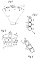
- the indicated in Fig. 1 vacuum coating system for evaporating Coating layers on optical substrates includes an evacuable via a vacuum pump known recipients (not shown).
- each substrate carrier 2 means for clamping of a substrate to be coated on both sides or for holding comprises two substrates to be coated on one side (not shown).
- the substrate supports 2 according to the invention are explained in more detail below described.
- a central evaporation source 4 is located in the lower region of the recipient indicated that in a known manner a conical vaporization jet 5th generated for vapor deposition of the surfaces held by the substrate carriers 2 Substrates.
- the substrate surfaces of the substrates to be vapor-deposited after each Twisting the substrate carrier 2 by 180 ° always in an exact angular position to the vaporization jet rising conically in the center of the recipient bring to optimal, uniform precipitation on each substrate surface can be achieved according to the invention in a radial extension of the Substrate carrier 2 at least two receiving areas for one substrate each provided between which recording areas each one, the Substrate carrier hinge or hinge 6 dividing into sections 12, 22 is located around which the substrate support sections with the substrate after both Sides freely relative to each other up to a predetermined angle are tiltable, as indicated in Fig. 1 by the dashed line.
- the Substrate carrier 2 from a dome-shaped plate, also in three Sections 12, 22 and 23 is divided by joint means 6, the middle Section 22 here means for holding three side by side Has substrates.
- the relative size of the substrates to the dome-shaped substrate carrier 2 Of course, even more substrates can be applied.
- a substrate carrier 2 according to FIG. 4 there is a strip-shaped substrate carrier 2 in three receiving areas for one each Provided substrate, between which receiving areas each hinge dividing the substrate carrier into sections 12, 22 and 23 or Hinge 6 is located around which the substrate support sections with the substrate free on both sides relative to each other up to a predetermined angle are tiltable.
- the shape of the substrate carrier is different as far as this allows, the substrate support sections with the substrate on both sides relative to each other up to one predetermined angle are freely tiltable.
Landscapes
- Chemical & Material Sciences (AREA)
- Chemical Kinetics & Catalysis (AREA)
- Engineering & Computer Science (AREA)
- Materials Engineering (AREA)
- Mechanical Engineering (AREA)
- Metallurgy (AREA)
- Organic Chemistry (AREA)
- Physical Vapour Deposition (AREA)
- Surface Treatment Of Optical Elements (AREA)
Description
Die vorliegende Erfindung betrifft einen Substrat-Täger für Vakuum-Beschichtungsanlagen zum Aufdampfen von Vergütungsschichten auf Flächen optischer Substrate, wie Kunststoff-Brillengläser, welche auf eine Mehrzahl solcher Träger aufspannbar sind, die sich in einem evakuierbaren Rezipienten oberhalb von auswechselbaren Verdampfungsquellen befinden.The present invention relates to a substrate carrier for vacuum coating systems for vapor deposition of coating layers on surfaces optically Substrates, such as plastic eyeglass lenses, which are placed on a plurality of such carriers that can be clamped in an evacuable recipient above replaceable evaporation sources.
Bei bekannten Einrichtungen dieser Art zum Aufdampfen von mindestens einer Oberflächenschicht auf optische Substrate, insbesondere Brillengläser, im Vakuum, werden eine vorgegebene Anzahl solcher Substrate nach dem Aufdampfen von in der Regel mehreren Schichten aus der Ebene, in welcher die Substratflächen der Wirkung der auswechselbaren Verdampfungsquellen ausgesetzt waren, herausbewegt und nochmals eine gleiche Anzahl Substratflächen in diese Ebene hineinbewegt, um diese ebenfalls nachfolgend einmal oder mehrmals zu bedampfen. In known devices of this type for the vapor deposition of at least one Surface layer on optical substrates, especially glasses, in Vacuum, a predetermined number of such substrates after the Evaporating generally several layers from the level in which the Substrate surfaces of the action of the interchangeable evaporation sources were exposed, moved out and again an equal number Substrate surfaces moved into this plane, also around this to vaporize one or more times.
Hierfür ist beispielsweise ein unter Vakuum setzbarer Drehtisch gebräuchlich, an dessen Umfang eine Mehrzahl Stationen zur lösbaren Befestigung von Substraten angeordnet sind. Diese Einrichtung umfasst weiter mindestens eine, mit den zugewendeten Substratflächen in Wirkungsverbindung stehende Verdampfungsquelle. Hierbei ist jede Station mit einem Substrat-Träger bestückt, an dem sich Haltemittel für die lösbare Befestigung von jeweils einem Substrat befinden. Sind dann auf den Substratflächen der einen Seite die einzelnen Vergütungsschichten nacheinander aufgedampft, werden die Substrat-Träger durch Rotation des Drehtisches gewendet und dann die anderen Substratflächen bedampft.For this purpose, for example, a turntable that can be placed under vacuum is customary the scope of a plurality of stations for releasable attachment of Substrates are arranged. This facility further comprises at least one, in operative connection with the facing substrate surfaces Evaporation source. Each station is equipped with a substrate carrier, on which there are holding means for the releasable attachment of one substrate each are located. Then are the individual on the substrate surfaces of one side Coating layers are evaporated one after the other, the substrate carrier by rotating the turntable and then the other substrate surfaces steamed.
Ferner ist es bekannt, Substrat-Träger als sogenannte Kalotten auszubilden, um eine Mehrzahl Substrate auf die flächigen, kreissegmentförmigen Träger aufzubringen. Eine Mehrzahl solcher Kalotten erstrecken sich jeweils kuppelförmig und drehbar im oberen Teil des Rezipienten, wodurch dann mit jeder Kalotte eine Mehrzahl Substrate jeweils gleichzeitig gewendet werden können.It is also known to form substrate carriers as so-called spherical caps in order to to apply a plurality of substrates to the flat, segment-shaped supports. A plurality of such domes each extend dome-shaped and rotatable in the upper part of the recipient, which then creates one with each cap A plurality of substrates can be turned over at the same time.
Problematisch bei solchen Anordnungen ist, dass der zentrisch im Rezipienten kegelförmig aufsteigende Bedampfungsstrahl eine genaue Winkelstellung der zu bedampfenden Substratflächen zum Strahlenkegel erfordert, um auf jeder Fläche einen optimalen, gleichförmigen Niederschlag zu erreichen.The problem with such arrangements is that they are centered in the recipient conical ascending vaporization jet an exact angular position of the Evaporating substrate areas to the beam cone requires to be on every area to achieve an optimal, uniform precipitation.
Dies ist bei einer Anordnung der radial von einem Drehtisch abragenden und um 180° über eine Achse wendbaren Substrat-Träger mit jeweils einem Substrat durch Schrägstellung der Achsen ohne weiteres erreichbar. This is in the case of an arrangement which projects radially from and around a turntable 180 ° reversible substrate carrier with one substrate each easily accessible by tilting the axes.
Bei den kalottenförmigen Substrat-Trägern, bei denen eine Mehrzahl Substrate auf die flächigen, kreissegmentförmigen Träger aufzubringen sind, ist dies aber nicht ohne weiteres ausreichend.In the case of the dome-shaped substrate carriers in which a plurality of substrates but this is to be applied to the flat, segment-shaped supports not easily sufficient.
Bei diesen kalottenförmigen Substrat-Trägern wurden deshalb schon Substrathalterungen an den Trägern vorgesehen, die mit dem Substrat nach beiden Seiten aus der Trägerplattenebene bis zu einem vorgegebenen Winkel heraus frei kippbar sind.For this reason, substrate holders have already been used for these dome-shaped substrate carriers provided on the supports that match the substrate after both Pages out of the carrier plate level up to a predetermined angle are freely tiltable.
Solche Substrathalterungen an den Trägern sind allerdings sehr kompliziert und störanfällig.Such substrate holders on the carriers are very complicated and prone to failure.
Es ist deshalb Aufgabe der vorliegenden Erfindung, Substrat-Träger der vorgenannten Art so auszugestalten, dass diese in sehr einfacher Weise die zu bedampfenden Substratflächen immer in eine genaue Winkelstellung zum zentrisch im Rezipienten kegelförmig aufsteigende Bedampfungsstrahl bringen, um auf jeder Fläche einen optimalen, gleichförmigen Niederschlag zu erreichen.It is therefore an object of the present invention to support the substrates mentioned above Art in such a way that they are very easy to use steaming substrate surfaces always in an exact angular position to bring the vaporization jet rising conically in the center of the recipient, in order to achieve an optimal, uniform precipitation on every surface.
Dies wird bei einem Substrat-Täger für Vakuum-Beschichtungsanlagen zum Aufdampfen von Vergütungsschichten auf Flächen optischer Substrate, wie Kunststoff-Brillengläser, welche auf eine Mehrzahl solcher Träger aufspannbar sind, die sich in einem evakuierbaren Rezipienten oberhalb von auswechselbaren Verdampfungsquellen befinden, dadurch erreicht, dass in radialer Ausdehnung des Substrat-Trägers mindestens zwei Aufnahmebereiche für jeweils ein Substrat vorgesehen sind, zwischen welchen Aufnahmebereichen sich jeweils ein, den Substrat-Träger in Abschnitte unterteilendes Scharnier oder Gelenk befindet, um das die Substrat-Träger-Abschnitte mit dem Substrat nach beiden Seiten hin relativ zueinander bis zu einem vorgegebenen Winkel frei kippbar sind.This is the case with a substrate carrier for vacuum coating systems for vapor deposition of coating layers on surfaces of optical substrates, such as Plastic glasses, which can be clamped onto a plurality of such carriers are in an evacuable recipient above exchangeable Evaporation sources are located in that achieved in radial Expansion of the substrate carrier for at least two receiving areas In each case, a substrate is provided, between which receiving areas each a hinge or dividing the substrate carrier into sections Hinge is located around which the substrate support sections face the substrate both sides relative to each other up to a predetermined angle are tiltable.
Unabhängig der Form des Substrat-Trägers und unabhängig seiner Anzahl durch Scharniermittel oder Gelenkmittel unterteilter, Substrate tragender Abschnitte ist es nunmehr möglich, dass, nach jedem Verdrehen der Substrat-Träger um 180°, die zu bedampfenden Substratflächen immer in eine genaue Winkelstellung zum zentrisch im Rezipienten kegelförmig aufsteigenden Bedampfungsstrahl gelangen, wodurch auf jeder Substratfläche ein optimaler, gleichförmiger Niederschlag erreicht wird.Regardless of the shape of the substrate carrier and regardless of its number Hinge means or hinge means of divided sections carrying substrates it is now possible that, after each rotation of the substrate carrier by 180 °, the substrate surfaces to be vaporized always in an exact angular position the cone-shaped vaporization jet arrives centrally in the recipient, which ensures optimal, uniform precipitation on every substrate surface is achieved.
Eine bevorzugte Ausgestaltung ist dann möglich durch mindestens zwei, sich radial erstreckende und an der Drehachse anschliessende Abschnitte, welche aus kreisförmigen Halteteilen für die Substrate bestehen und welche durch Scharniere oder Gelenke verbunden sind, um welche die Substrat-Träger-Abschnitte mit dem Substrat nach beiden Seiten hin relativ zueinander bis zu einem vorgegebenen Winkel frei kippbar sind; oder durch eine kalottenförmige Platte, die in mindestens zwei Abschnitte durch Gelenkmittel unterteilt ist, um welche die Substrat-Träger-Abschnitte mit dem Substrat nach beiden Seiten hin relativ zueinander bis zu einem vorgegebenen Winkel frei kippbar sind, wobei mindestens der mittlere Abschnitt Mittel zur Aufnahme von mindestens zwei nebeneinanderliegenden Substraten aufweist; oder durch eine streifenförmige Anordnung, die in mindestens zwei Aufnahmebereiche für jeweils ein Substrat aufgeteilt ist, zwischen welchen Aufnahmebereichen sich jeweils ein, den Substrat-Träger in Abschnitte unterteilendes Scharnier oder Gelenk befindet, um welches die Substrat-Träger-Abschnitte mit dem Substrat nach beiden Seiten hin relativ zueinander bis zu einem vorgegebenen Winkel frei kippbar sind.A preferred embodiment is then possible by at least two radially extending and adjoining the axis of rotation, which consist of circular holding parts for the substrates and which by Hinges or hinges are connected around which the substrate support sections with the substrate on both sides relative to each other up to are freely tiltable at a predetermined angle; or by a dome-shaped Plate that is divided into at least two sections by hinge means which the substrate support sections with the substrate on both sides are freely tiltable relative to each other up to a predetermined angle, wherein at least the middle section means for receiving at least two has adjacent substrates; or by a strip-shaped Arrangement in at least two receiving areas for one substrate each is divided, between which recording areas each, the Substrate carrier located in section-dividing hinge or hinge which the substrate carrier sections with the substrate on both sides are freely tiltable relative to each other up to a predetermined angle.
Beispielsweise Ausführungsformen des Erfindungsgegenstandes sind nachfolgend anhand der Zeichnung näher erläutert. Es zeigen:
- Fig. 1
- in schematischer, vereinfachter Darstellung in Seitenansicht eine
Vakuum-Beschichtungsanlage mit erfindungsgemässen Substrat-Trägern;
und - Fig. 2 bis 4
- in Draufsicht und in grösserem Massstab Ausführungsformen von erfindungsgemässen Substrat-Trägern.
- Fig. 1
- a schematic, simplified representation in side view of a vacuum coating system with substrate carriers according to the invention;
and - 2 to 4
- In plan view and on a larger scale, embodiments of substrate supports according to the invention.
Die in Fig. 1 angedeutete Vakuum-Beschichtungsanlage zum Aufdampfen von Vergütungsschichten auf optische Substrate, beispielsweise Kunststoff-Brillenglaser, umfasst einen, über eine Vakuum-Pumpe evakuierbaren, ansich bekannten Rezipienten (nicht gezeigt). The indicated in Fig. 1 vacuum coating system for evaporating Coating layers on optical substrates, for example plastic eyeglass lenses, includes an evacuable via a vacuum pump known recipients (not shown).
Im oberen Kammerbereich dieses Rezipienten befindet sich eine sogenannte
Wendeträger-Vorrichtung 1 mit einer Mehrzahl, hier zwei erkennbare radial um
die kreisförmige Wendeträger-Vorrichtung 1 angeordnete, erfindungsgemässe
Substrat-Träger 2, die je an einer, temporär um 180° verdrehbaren Drehachse 3
abgestützt sind, wobei jeder Substrat-Träger 2 Mittel zum klemmenden Festhalten
eines beidseitig zu beschichtenden Substrates oder zum Festhalten von
zwei einseitig zu beschichtenden Substraten umfasst (nicht gezeigt).In the upper chamber area of this recipient there is a so-called
Reversible carrier device 1 with a plurality, here two recognizable radially around
the circular turning carrier device 1 arranged according to the
Die erfindungsgemässen Substrat-Träger 2 werden nachfolgend noch näher beschrieben.The substrate supports 2 according to the invention are explained in more detail below described.
Im unteren Bereich des Rezipienten ist eine zentrische Verdampfungsquelle 4
angedeutet, die in bekannter Weise einen kegelförmigen Bedampfungsstrahl 5
erzeugt zum Bedampfen der Flächen der von den Substrat-Trägern 2 gehaltenen
Substrate.A central evaporation source 4 is located in the lower region of the recipient
indicated that in a known manner a conical vaporization jet 5th
generated for vapor deposition of the surfaces held by the
Um nun die zu bedampfenden Substratflächen der Substrate nach jedem
Verdrehen der Substrat-Träger 2 um 180° immer in eine genaue Winkelstellung
zum zentrisch im Rezipienten kegelförmig aufsteigenden Bedampfungsstrahl zu
bringen, um auf jeder Substratfläche einen optimalen, gleichförmige Niederschlag
zu erreichen, sind erfindungsgemäss in radialer Ausdehnung des
Substrat-Trägers 2 mindestens zwei Aufnahmebereiche für jeweils ein Substrat
vorgesehen, zwischen welchen Aufnahmebereichen sich jeweils ein, den
Substrat-Träger in Abschnitte 12,22 unterteilendes Scharnier oder Gelenk 6
befindet, um das die Substrat-Träger-Abschnitte mit dem Substrat nach beiden
Seiten hin relativ zueinander bis zu einem vorgegebenen Winkel heraus frei
kippbar sind, wie das in Fig. 1 durch die gestrichelte Linie angedeutet ist.In order now the substrate surfaces of the substrates to be vapor-deposited after each
Twisting the
Unabhängig der Form des Substrat-Trägers 2 und unabhängig seiner Anzahl
durch Scharniermittel oder Gelenkmittel 6 unterteilter, Substrate tragender
Abschnitte 12,22 ist es nunmehr möglich, dass die zu bedampfenden
Substratflächen immer in eine genaue Winkelstellung zum zentrisch im
Rezipienten kegelförmig aufsteigenden Bedampfungsstrahl 5 gelangen, wodurch
auf jeder Substratfläche ein optimaler, gleichförmiger Niederschlag erreicht wird,
wie das Fig. 1 erkennen lässt.Regardless of the shape of the
Bei der Ausführungsvariante eines Substrat-Trägers 2 gemäss Fig. 2 sind drei,
sich radial erstreckende und an der Drehachse 3 anschliessende Abschnitte 12,
22 und 23 vorgesehen, welche aus kreisförmigen Halteteilen für die Substrate
bestehen und welche hier durch zwei Scharniere oder Gelenke 6 verbunden
sind.In the embodiment variant of a
Bei der Ausführungsvariante eines Substrat-Trägers 2 gemäss Fig. 3 besteht der
Substrat-Träger 2 aus einer kalottenförmigen Platte, die ebenfalls in drei
Abschnitte 12, 22 und 23 durch Gelenkmittel 6 unterteilt ist, wobei der mittlere
Abschnitt 22 hier Mittel zur Aufnahme von drei nebeneinanderliegenden
Substraten aufweist.In the embodiment variant of a
Je nach relativer Grösse der Substrate zum kalottenförmigen Substrat-Träger 2
können natürlich auch noch mehr Substrate aufbringbar sein.Depending on the relative size of the substrates to the dome-
Bei der Ausführungsvariante eines Substrat-Trägers 2 gemäss Fig. 4 ist ein
streifenförmiger Substrat-Träger 2 in drei Aufnahmebereiche für jeweils ein
Substrat vorgesehen, zwischen welchen Aufnahmebereichen sich jeweils ein,
den Substrat-Träger in Abschnitte 12, 22 und 23 unterteilendes Scharnier oder
Gelenk 6 befindet, um welches die Substrat-Träger-Abschnitte mit dem Substrat
nach beiden Seiten hin relativ zueinander bis zu einem vorgegebenen Winkel frei
kippbar sind.In the embodiment variant of a
Aus dem Vorstehenden ergibt sich, dass die Form der Substrat-Träger unterschiedlich sein kann, soweit diese gestattet, dass die Substrat-Träger-Abschnitte mit dem Substrat nach beiden Seiten hin relativ zueinander bis zu einem vorgegebenen Winkel frei kippbar sind.It follows from the above that the shape of the substrate carrier is different as far as this allows, the substrate support sections with the substrate on both sides relative to each other up to one predetermined angle are freely tiltable.
Es wird Schutz beansprucht wie folgt:Protection is claimed as follows:
Claims (4)
- Substrate holder for vacuum coating apparatus, designed for the vacuum evaporation of antireflection coatings onto optical substrate surfaces, such as plastic spectacle lenses, which can be clamped onto a plurality of such holders, located above replaceable evaporation sources in a container that can be evacuated,
characterized in that
at least two receiving regions for one each substrate are provided in radial extension of the substrate holder (2), between which receiving regions respectively one hinge or joint (6) is located, which subdivides the substrate holder (2) into segments (12, 22) and around which the substrate holder segments with the substrate can be swiveled freely toward both sides, relative to each other and up to a predetermined angle. - Substrate holder according to Claim 1, characterized by at least two, radially extending segments (12, 22 and 23) that adjoin the rotational axis (3), which consist of circular holders for the substrates and are connected by hinges or joints (6), around which the substrate holder segments with the substrate can be swiveled freely toward both sides, relative to each other and up to a predetermined angle.
- Substrate holder according to Claim 1, characterized by a calotte-shaped plate, which is subdivided into at least two segments (12, 22 and 23) by hinged means (6), around which the substrate holder segments with the substrate can be swiveled freely toward both sides, relative to each other and up to a predetermined angle, wherein at least the center segment (22) has means for receiving at least two side-by-side arranged substrates.
- Substrate holder according to Claim 1, characterized by a strip-type arrangement, divided into at least two receiving regions for one each substrate, between which receiving regions one each hinge or joint (6) is located that subdivides the substrate holder into segments (12, 22 and 23) and around which the substrate holder segments can be swiveled freely toward both sides, relative to each other and up to a predetermined angle.
Applications Claiming Priority (3)
| Application Number | Priority Date | Filing Date | Title |
|---|---|---|---|
| CH1200/96 | 1996-05-10 | ||
| CH01200/96A CH691308A5 (en) | 1996-05-10 | 1996-05-10 | Substrate support for vacuum coating equipment. |
| CH120096 | 1996-05-10 |
Publications (2)
| Publication Number | Publication Date |
|---|---|
| EP0806492A1 EP0806492A1 (en) | 1997-11-12 |
| EP0806492B1 true EP0806492B1 (en) | 2000-08-09 |
Family
ID=4204857
Family Applications (1)
| Application Number | Title | Priority Date | Filing Date |
|---|---|---|---|
| EP97107376A Expired - Lifetime EP0806492B1 (en) | 1996-05-10 | 1997-05-05 | Substrate holder for vacuum coating apparatus |
Country Status (6)
| Country | Link |
|---|---|
| US (1) | US6082298A (en) |
| EP (1) | EP0806492B1 (en) |
| JP (1) | JPH1068066A (en) |
| CN (1) | CN1124363C (en) |
| CH (1) | CH691308A5 (en) |
| DE (1) | DE59702124D1 (en) |
Families Citing this family (20)
| Publication number | Priority date | Publication date | Assignee | Title |
|---|---|---|---|---|
| FR2802947B1 (en) * | 1999-12-28 | 2002-04-12 | St Microelectronics Sa | SUBSTRATE SUPPORT FOR EVAPORATIVE COATING SYSTEM |
| DE10261362B8 (en) * | 2002-12-30 | 2008-08-28 | Osram Opto Semiconductors Gmbh | Substrate holder |
| DE102004063703A1 (en) * | 2004-12-28 | 2006-07-06 | Schott Ag | Vacuum coating system |
| DE102005045718B4 (en) | 2005-09-24 | 2009-06-25 | Applied Materials Gmbh & Co. Kg | Carrier for a substrate |
| CN101041889B (en) * | 2006-03-21 | 2010-05-12 | 鸿富锦精密工业(深圳)有限公司 | Coating method |
| DE102007062618B4 (en) | 2007-12-22 | 2009-11-05 | Carl Zeiss Vision Gmbh | Method and device for coating glasses |
| EP2093018B2 (en) * | 2008-02-25 | 2017-11-01 | Satisloh AG | Block piece for holding an optical workpiece, in particular a spectacle lens, for processing thereof, and method for manufacturing spectacle lenses according to a prescription |
| CN101597747B (en) * | 2008-06-05 | 2012-06-20 | 鸿富锦精密工业(深圳)有限公司 | Optical coating device |
| TWI414615B (en) * | 2008-06-20 | 2013-11-11 | Hon Hai Prec Ind Co Ltd | Optical coating device |
| ES2368678T3 (en) * | 2008-06-26 | 2011-11-21 | Satisloh Ag | PROCEDURE FOR MANUFACTURING GLASS LENSES ACCORDING TO A PRESCRIPTION. |
| CN102234782A (en) * | 2010-04-26 | 2011-11-09 | 鸿富锦精密工业(深圳)有限公司 | Coated umbrella stand |
| CN101955321A (en) * | 2010-05-21 | 2011-01-26 | 蚌埠翼诚玻璃有限公司 | Split type film coating frame |
| KR20120083712A (en) * | 2011-01-18 | 2012-07-26 | 삼성엘이디 주식회사 | Susceptor and chemical vapor deposition apparatus comprising the same |
| CN103014617B (en) * | 2011-09-22 | 2014-05-14 | 株式会社新柯隆 | Thin film forming apparatus |
| LU92190B1 (en) | 2013-05-06 | 2014-11-07 | Satisloh Gmbh | Multi part blocking piece |
| LU92191B1 (en) | 2013-05-06 | 2014-11-07 | Satisloh Gmbh | Multimaterial block piece |
| EP2963458B1 (en) | 2014-07-05 | 2022-02-02 | Satisloh AG | Lens blank having a temporary grip coating for a method for manufacturing spectacle lenses according to a prescription |
| JP6019310B1 (en) * | 2015-04-16 | 2016-11-02 | ナルックス株式会社 | Vapor deposition apparatus and manufacturing method including film forming process by vapor deposition apparatus |
| CN106707725B (en) * | 2017-01-20 | 2022-07-22 | 中国电子科技集团公司第十二研究所 | Optical transmission window for atomic clock |
| EP3542956A1 (en) | 2018-03-23 | 2019-09-25 | Carl Zeiss Vision International GmbH | Method for manufacturing spectacle lenses according to a prescription |
Family Cites Families (8)
| Publication number | Priority date | Publication date | Assignee | Title |
|---|---|---|---|---|
| NL7205670A (en) * | 1972-03-16 | 1973-09-18 | ||
| US3859956A (en) * | 1974-01-10 | 1975-01-14 | Bell Telephone Labor Inc | Multiworkpiece condensation coating apparatus |
| JPS58107484A (en) * | 1981-12-19 | 1983-06-27 | Olympus Optical Co Ltd | Reverse type vapor deposition apparatus in thin film forming apparatus |
| JPS61130484A (en) * | 1984-11-28 | 1986-06-18 | Olympus Optical Co Ltd | Device for holding optical part of vacuum deposition device |
| CH668430A5 (en) * | 1986-07-31 | 1988-12-30 | Satis Vacuum Ag | VACUUM COATING SYSTEM FOR OPTICAL SUBSTRATES. |
| DE3921671A1 (en) * | 1989-07-01 | 1991-01-03 | Leybold Ag | LENS HOLDER, ESPECIALLY HOLDER FOR EYE GLASS LENSES TO BE COATED IN A HIGH VACUUM VACUUM DEVICE OR SPUTTER |
| CH681308A5 (en) * | 1990-05-22 | 1993-02-26 | Satis Vacuum Ag | |
| US5382345A (en) * | 1993-02-16 | 1995-01-17 | Industrial Technology Research Institute | Apparatus for simultaneously coating a film of magneto-optical recording medium on a plurality of disk substrates |
-
1996
- 1996-05-10 CH CH01200/96A patent/CH691308A5/en not_active IP Right Cessation
-
1997
- 1997-05-05 EP EP97107376A patent/EP0806492B1/en not_active Expired - Lifetime
- 1997-05-05 DE DE59702124T patent/DE59702124D1/en not_active Expired - Lifetime
- 1997-05-07 JP JP9117151A patent/JPH1068066A/en active Pending
- 1997-05-09 CN CN97111504.4A patent/CN1124363C/en not_active Expired - Lifetime
- 1997-05-12 US US08/854,690 patent/US6082298A/en not_active Expired - Lifetime
Also Published As
| Publication number | Publication date |
|---|---|
| CH691308A5 (en) | 2001-06-29 |
| EP0806492A1 (en) | 1997-11-12 |
| US6082298A (en) | 2000-07-04 |
| DE59702124D1 (en) | 2000-09-14 |
| CN1170773A (en) | 1998-01-21 |
| JPH1068066A (en) | 1998-03-10 |
| CN1124363C (en) | 2003-10-15 |
Similar Documents
| Publication | Publication Date | Title |
|---|---|---|
| EP0806492B1 (en) | Substrate holder for vacuum coating apparatus | |
| CH668430A5 (en) | VACUUM COATING SYSTEM FOR OPTICAL SUBSTRATES. | |
| CH681308A5 (en) | ||
| DE10324928A1 (en) | Vacuum coating system | |
| EP0547312A1 (en) | Substrate-holding and -turning device for vacuum processes | |
| DE2950768C2 (en) | Device for applying a safety lining made of molten plastic in the form of spots to the thread of a metal screw part | |
| DE3513137A1 (en) | Multiple retaining device for substrates to be treated, for example to be cleaned and then to be coated by vacuum deposition or cathode sputtering | |
| EP0959147A2 (en) | Lens holder | |
| DE69006870T2 (en) | Device for covering a flat surface with a layer of uniform thickness. | |
| EP0806493B1 (en) | Vapor deposition apparatus for coating optical substrates | |
| DE2337204A1 (en) | Spectacle lens vapour deposition holder - comprises turntable with radial axis rotatable twin lens holders | |
| EP0368202B1 (en) | Method for coating a substrate matrix for a flat display | |
| EP0806491B1 (en) | Vapor deposition method for coating optical substrates | |
| EP0396067B1 (en) | Profile grinding device | |
| DE19918405B4 (en) | Mirror system for stereoscopic image erection | |
| DE69004048T2 (en) | Device for applying a coating agent on a substrate surface. | |
| EP0556480B1 (en) | Method for applying thin coatings on large curved surfaces, especially cathode ray tube screen, by a centrifugal coating process | |
| EP1050597B1 (en) | Vacuum coating apparatus | |
| EP0385157A1 (en) | Substrate holders to support glass lenses for coating, and domed substrate carrier to support the holders | |
| DD292029A5 (en) | SUBSTRATE HOLDING DEVICE FOR HARD COATING OF DISCS, ROTATION SYMMETRIC SUBSTRATES | |
| DD200410A1 (en) | ADJUSTMENT DEVICE FOR PREPARING SPHAERIC FLAKES AT WORKPIECES | |
| DD267263B5 (en) | Substrate holding device for receiving and moving substrates with a complicated surface shape | |
| DE606821C (en) | Adjustment device for a pair of binocular microscopes | |
| DE3838012A1 (en) | WORKPIECE CARRIER | |
| DE8900116U1 (en) | Workpiece carrier for holding spectacle lenses or similar when coating with a liquid, in particular a hard lacquer |
Legal Events
| Date | Code | Title | Description |
|---|---|---|---|
| PUAI | Public reference made under article 153(3) epc to a published international application that has entered the european phase |
Free format text: ORIGINAL CODE: 0009012 |
|
| AK | Designated contracting states |
Kind code of ref document: A1 Designated state(s): DE FR GB IT |
|
| 17P | Request for examination filed |
Effective date: 19980512 |
|
| GRAG | Despatch of communication of intention to grant |
Free format text: ORIGINAL CODE: EPIDOS AGRA |
|
| 17Q | First examination report despatched |
Effective date: 19990723 |
|
| GRAG | Despatch of communication of intention to grant |
Free format text: ORIGINAL CODE: EPIDOS AGRA |
|
| GRAH | Despatch of communication of intention to grant a patent |
Free format text: ORIGINAL CODE: EPIDOS IGRA |
|
| GRAH | Despatch of communication of intention to grant a patent |
Free format text: ORIGINAL CODE: EPIDOS IGRA |
|
| GRAA | (expected) grant |
Free format text: ORIGINAL CODE: 0009210 |
|
| AK | Designated contracting states |
Kind code of ref document: B1 Designated state(s): DE FR GB IT |
|
| REF | Corresponds to: |
Ref document number: 59702124 Country of ref document: DE Date of ref document: 20000914 |
|
| GBT | Gb: translation of ep patent filed (gb section 77(6)(a)/1977) |
Effective date: 20000918 |
|
| ET | Fr: translation filed | ||
| ITF | It: translation for a ep patent filed | ||
| PLBE | No opposition filed within time limit |
Free format text: ORIGINAL CODE: 0009261 |
|
| STAA | Information on the status of an ep patent application or granted ep patent |
Free format text: STATUS: NO OPPOSITION FILED WITHIN TIME LIMIT |
|
| 26N | No opposition filed | ||
| REG | Reference to a national code |
Ref country code: GB Ref legal event code: IF02 |
|
| REG | Reference to a national code |
Ref country code: FR Ref legal event code: CD Ref country code: FR Ref legal event code: CA |
|
| REG | Reference to a national code |
Ref country code: FR Ref legal event code: PLFP Year of fee payment: 20 |
|
| PGFP | Annual fee paid to national office [announced via postgrant information from national office to epo] |
Ref country code: DE Payment date: 20160620 Year of fee payment: 20 Ref country code: GB Payment date: 20160630 Year of fee payment: 20 |
|
| PGFP | Annual fee paid to national office [announced via postgrant information from national office to epo] |
Ref country code: FR Payment date: 20160527 Year of fee payment: 20 Ref country code: IT Payment date: 20160527 Year of fee payment: 20 |
|
| REG | Reference to a national code |
Ref country code: DE Ref legal event code: R071 Ref document number: 59702124 Country of ref document: DE |
|
| REG | Reference to a national code |
Ref country code: GB Ref legal event code: PE20 Expiry date: 20170504 |
|
| PG25 | Lapsed in a contracting state [announced via postgrant information from national office to epo] |
Ref country code: GB Free format text: LAPSE BECAUSE OF EXPIRATION OF PROTECTION Effective date: 20170504 |