EP0806398A2 - Installation for disinfection of fluids such as water - Google Patents
Installation for disinfection of fluids such as water Download PDFInfo
- Publication number
- EP0806398A2 EP0806398A2 EP97106995A EP97106995A EP0806398A2 EP 0806398 A2 EP0806398 A2 EP 0806398A2 EP 97106995 A EP97106995 A EP 97106995A EP 97106995 A EP97106995 A EP 97106995A EP 0806398 A2 EP0806398 A2 EP 0806398A2
- Authority
- EP
- European Patent Office
- Prior art keywords
- container
- lamps
- perforated
- disc
- chamber
- Prior art date
- Legal status (The legal status is an assumption and is not a legal conclusion. Google has not performed a legal analysis and makes no representation as to the accuracy of the status listed.)
- Granted
Links
Images

Classifications
-
- C—CHEMISTRY; METALLURGY
- C02—TREATMENT OF WATER, WASTE WATER, SEWAGE, OR SLUDGE
- C02F—TREATMENT OF WATER, WASTE WATER, SEWAGE, OR SLUDGE
- C02F1/00—Treatment of water, waste water, or sewage
- C02F1/30—Treatment of water, waste water, or sewage by irradiation
- C02F1/32—Treatment of water, waste water, or sewage by irradiation with ultraviolet light
- C02F1/325—Irradiation devices or lamp constructions
-
- B—PERFORMING OPERATIONS; TRANSPORTING
- B01—PHYSICAL OR CHEMICAL PROCESSES OR APPARATUS IN GENERAL
- B01J—CHEMICAL OR PHYSICAL PROCESSES, e.g. CATALYSIS OR COLLOID CHEMISTRY; THEIR RELEVANT APPARATUS
- B01J19/00—Chemical, physical or physico-chemical processes in general; Their relevant apparatus
- B01J19/08—Processes employing the direct application of electric or wave energy, or particle radiation; Apparatus therefor
- B01J19/12—Processes employing the direct application of electric or wave energy, or particle radiation; Apparatus therefor employing electromagnetic waves
- B01J19/122—Incoherent waves
- B01J19/123—Ultraviolet light
-
- C—CHEMISTRY; METALLURGY
- C02—TREATMENT OF WATER, WASTE WATER, SEWAGE, OR SLUDGE
- C02F—TREATMENT OF WATER, WASTE WATER, SEWAGE, OR SLUDGE
- C02F2201/00—Apparatus for treatment of water, waste water or sewage
- C02F2201/32—Details relating to UV-irradiation devices
- C02F2201/324—Lamp cleaning installations, e.g. brushes
Definitions
- the invention relates to a system for the disinfection of flowing media, such as water, with an essentially cylindrical container in which a reactor space with UV lamps located on the circumference of a concentrically arranged partial circle is provided and the at least one inlet and one outlet opening for the medium flowing through the reactor chamber parallel to the axis.
- the reactor space is formed by an annular space provided on the outside of a drain pipe centrally penetrating the container and containing the axially parallel UV lamps, through which the medium supplied from the inlet opening on the lamps and flows through the outside of the drain pipe until it finally reaches the end of the annular space and the mouth of the central drain pipe leading to the drain opening located there.
- the invention has for its object to develop the system of the type mentioned so that a more compact design with lower energy consumption is possible when operating the system.
- the system according to the invention in which this object is achieved, is characterized essentially by the fact that the reactor space is arranged in the center of the container and that the UV lamps pass through a discharge chamber, which is located on one side of the container approximately in the Drain opening located in the middle of the container is directly connected, and extend through the reactor chamber into an inlet chamber which directly adjoins the inlet opening located approximately in the middle of the container on the other side of the container.
- the medium reaches the effective range of the UV lamps in a relatively short way from the inlet opening of the container and likewise, namely practically immediately after leaving this effective range, exits the container again through the discharge opening.
- the space required for the media guidance within the container is thus reduced to a minimum and the media treatment is more effective.
- This perforated plate is expediently designed in the form of a central perforated disk and at least one perforated ring which is complementary to the disk edge and complements the disk. In this practical way it is possible to choose an optimal flow cross-section for the perforated disc that differs from the perforated ring.
- the diameter of the perforated disc corresponds very favorably to the diameter of the pitch circle on which the axes of the UV lamps lie. In this way it is possible to detect the UV lamps on the one hand from the perforated disc edge and on the other hand from the perforated ring.
- the perforated metal sheet (s) is assigned a drive device for shifting along and thus cleaning the UV lamps.
- a wiping device is expediently assigned to the perforated disks.
- the container can be closed by a cover plate on which all UV lamps are fixed. This ensures that all UV lamps can be lifted and removed together from the container when loosening and removing the cover plate.
- the drive device serving the displacement drive for cleaning the UV radiators and connected to the perforated plate (s) is also fixed on the cover plate. In the event of any maintenance work, this gives the possibility of lifting and removing the entire drive device together with the perforated plates.
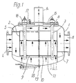
- the illustrated system for the disinfection of flowing media comprises an essentially cylindrical container 1, in which a reactor chamber 2 with UV lamps 3 located on the circumference of a concentrically arranged partial circle is provided.
- Each UV lamp 3 comprises in a conventional manner the actual tubular lamp, which is surrounded by a quartz protective tube.
- the reactor chamber 2, which is essentially cylindrical in shape like the container 1, is fixed on the side of the inlet opening 4 via an upper wall 5 on the inside of the container 1 and on the diametrically opposite side in the region of the outlet opening 6 analogously via a lower wall 7 1, the reactor space 2 is arranged in the center of the container 1.
- the UV lamps 3 extend through an outlet chamber 8, which is directly connected to the outlet opening 6 located approximately in the middle of the container on one side of the container. In addition, they extend through the reactor space 2 into an inlet chamber 9, which adjoins the inlet opening 4 located approximately in the middle of the container on the other side of the container.
- the arrows drawn in FIG. 1 illustrate the short path of the media flowing through the system from the inlet opening 4 to the outlet opening 6.
- perforated plates 10 and 11 are provided in the latter, which extend transversely to the container axis and through which the UV lamps 3 pass are.
- These perforated plates 10, 11 are provided with perforations 12a, cf. Fig. 2, different size or density provided, the flow rate per respective cross-sectional area can be optimized by their coordination.
- each perforated plate is designed in the form of a central perforated disk 12 and at least one perforated ring 13 that is complementary to the disk edge and thus complements the disk.
- the diameter of the perforated disk 12 corresponds, as can be seen in FIG. 2, to the diameter of the pitch circle on which the axes of the UV lamps 3 lie.
- the UV lamps can be detected on the one hand by the perforated disc edge and on the other hand by the perforated ring.
- Fig. 1 shows that the perforated plates 10, 11 is assigned a drive device 14 for moving the perforated plates and thus cleaning the UV lamp.
- the perforated disks 10, 11 expediently comprise a wiper device (not illustrated in more detail).
- the container 1 comprises a cover plate 15 which can be screwed to the edge of an opening in the container 1.
- cover plate 15 all UV lamps 3 are fixed on the one hand so that they can be lifted and removed together from the container 1 when the cover plate 15 is detached and removed. This also applies to the drive device 14 for actuating the sliding drive for cleaning the UV lamps 3.
- UV lamps are each fixed via a screw unit 16 with a seal on the cover plate 15, as is an automatic venting device 17.
- an emptying pipe for the complete emptying of the container 1, if necessary, there is an emptying pipe at its lowest point 18 provided.
- the intensity of UV radiation leaves are determined by means of a UV sensor 19 likewise provided in the bottom area of the container 1.
Landscapes
- Chemical & Material Sciences (AREA)
- Health & Medical Sciences (AREA)
- Toxicology (AREA)
- Organic Chemistry (AREA)
- Engineering & Computer Science (AREA)
- Environmental & Geological Engineering (AREA)
- Water Supply & Treatment (AREA)
- Hydrology & Water Resources (AREA)
- Life Sciences & Earth Sciences (AREA)
- Physics & Mathematics (AREA)
- Electromagnetism (AREA)
- General Health & Medical Sciences (AREA)
- Chemical Kinetics & Catalysis (AREA)
- Physical Water Treatments (AREA)
- Physical Or Chemical Processes And Apparatus (AREA)
- Solid-Sorbent Or Filter-Aiding Compositions (AREA)
- Apparatus For Disinfection Or Sterilisation (AREA)
Abstract
Description
Die Erfindung bezieht sich auf eine Anlage für die Entkeimung strömender Medien, wie Wasser, mit einem im wesentlichen zylindrischen Behälter, in dem ein Reaktorraum mit am Umfang eines konzentrisch angeordneten Teilkreises liegenden UV-Strahlern vorgesehen ist und der mindestens eine Zu- und eine Ablauföffnung für das den Reaktorraum achsparallel durchströmende Medium umfaßt.The invention relates to a system for the disinfection of flowing media, such as water, with an essentially cylindrical container in which a reactor space with UV lamps located on the circumference of a concentrically arranged partial circle is provided and the at least one inlet and one outlet opening for the medium flowing through the reactor chamber parallel to the axis.
Bei einer bekannten Entkeimungsanlage dieser Art (DE PS 28 51 013) ist der Reaktorraum durch einen an der Außenseite eines den Behälter zentral durchsetzenden Ablaufrohrs vorgesehenen, die achsparallelen UV-Strahler enthaltenden Ringraum gebildet, durch den das von der Zulauföffnung zugeführte Medium an den Strahlern sowie der Ablaufrohraußenseite entlang hindurchströmt, bis es schließlich das Ende des Ringraums und die dort befindliche Mündung des zur Ablauföffnung führenden zentralen Ablaufrohrs erreicht.In a known disinfection system of this type (DE PS 28 51 013), the reactor space is formed by an annular space provided on the outside of a drain pipe centrally penetrating the container and containing the axially parallel UV lamps, through which the medium supplied from the inlet opening on the lamps and flows through the outside of the drain pipe until it finally reaches the end of the annular space and the mouth of the central drain pipe leading to the drain opening located there.
Bei dieser Ausführung hat sich die Tatsache als nachteilig herausgestellt, daß das zu behandelnde Medium im Anschluß an die während der Durchströmung des Ringraums erfolgende Bestrahlung innerhalb des Behälters eine längere Wegstrecke ohne Bestrahlungsmöglichkeit zurücklegen muß, die praktisch dem Weg vom Zulauf bis zur Mündung des zentralen Ablaufrohrs entspricht. Dadurch verbleibt innerhalb der Anlage viel Raum ungenutzt, ganz abgesehen von Reibungskräften, die beim Hindurchpumpen der Medien durch die Anlage die Aufbringung zusätzlicher Energie erforderlich machen.In this embodiment, the fact that the medium to be treated has to travel a longer distance without irradiation possibility during the flow through the annulus, which is practically the path from the inlet to the mouth of the central drain pipe, has proven to be disadvantageous corresponds. As a result, a lot of space remains unused within the system, not to mention frictional forces, which require the application of additional energy when pumping the media through the system.
Der Erfindung liegt die Aufgabe zugrunde, die Anlage der eingangs genannten Art so weiter auszugestalten, daß eine kompaktere Ausbildung mit geringerem Energiebedarf beim Betrieb der Anlage ermöglicht ist.The invention has for its object to develop the system of the type mentioned so that a more compact design with lower energy consumption is possible when operating the system.
Die Anlage nach der Erfindung, bei der diese Aufgabe gelöst ist, zeichnet sich im wesentlichen dadurch aus, daß der Reaktorraum im Zentrum des Behälters angeordnet ist und daß sich die UV-Strahler durch eine Ablaufkammer, die mit einer sich an einer Behälterseite etwa in der Behältermitte befindlichen Ablauföffnung unmittelbar verbunden ist, und durch den Reaktorraum hindurch bis in eine Zulaufkammer hinein erstrecken, die sich an die an der anderen Behälterseite etwa in der Behältermitte befindliche Zulauföffnung unmittelbar anschließt.The system according to the invention, in which this object is achieved, is characterized essentially by the fact that the reactor space is arranged in the center of the container and that the UV lamps pass through a discharge chamber, which is located on one side of the container approximately in the Drain opening located in the middle of the container is directly connected, and extend through the reactor chamber into an inlet chamber which directly adjoins the inlet opening located approximately in the middle of the container on the other side of the container.
Bei einer derartigen Anlage ist in vorteilhafter Weise sichergestellt, daß das Medium auf relativ kurzem Wege von der Zulauföffnung des Behälters in den Wirkungsbereich der UV-Strahler gelangt und ebenso, nämlich praktisch unmittelbar nach Verlassen dieses Wirkungsbereichs durch die Ablauföffnung aus dem Behälter wieder austritt. Der Platzbedarf für die Medienführung innerhalb des Behälters ist somit auf ein Minimum reduziert und eine höhere Effektivität der Medienbehandlung erreicht.In such a system, it is advantageously ensured that the medium reaches the effective range of the UV lamps in a relatively short way from the inlet opening of the container and likewise, namely practically immediately after leaving this effective range, exits the container again through the discharge opening. The space required for the media guidance within the container is thus reduced to a minimum and the media treatment is more effective.
Als sehr günstig hat es sich weiterhin erwiesen, daß mit dieser Ausbildung die optimale Voraussetzung für eine Strömungssteuerung geschaffen ist, in dem im Reaktorraum mindestens ein sich quer zur Behälterachse erstreckendes, von den UV-Strahlern durchsetztes Lochblech mit Lochungen unterschiedlicher Größe bzw. Dichte vorgesehen ist, durch deren Abstimmung aufeinander die Durchflußmenge pro jeweiliger Querschnittsfläche optimierbar ist.It has also proven to be very favorable that this configuration creates the optimal prerequisite for flow control in which at least one in the reactor space Perforated plate extending through the axis of the container and penetrated by the UV lamps is provided with perforations of different sizes or densities, the coordination of which allows the flow rate per cross-sectional area to be optimized.
Zweckmäßigerweise ist dieses Lochblech in Form einer zentralen Lochscheibe und mindestens eines mit dem Scheibenrand komplementären und die Scheibe ergänzenden Lochrings ausgebildet. Auf diese praktische Weise ist die Möglichkeit gegeben, für die Lochscheibe einen gegenüber dem Lochring abweichenden optimalen Durchflußquerschnitt zu wählen.This perforated plate is expediently designed in the form of a central perforated disk and at least one perforated ring which is complementary to the disk edge and complements the disk. In this practical way it is possible to choose an optimal flow cross-section for the perforated disc that differs from the perforated ring.
In sehr günstiger Weise entspricht der Durchmesser der Lochscheibe dem Durchmesser des Teilkreises, auf dem die Achsen der UV-Strahler liegen. Auf diese Weise ist es möglich, die UV-Strahler einerseits vom Lochscheibenrand und andererseits vom Lochring zu erfassen.The diameter of the perforated disc corresponds very favorably to the diameter of the pitch circle on which the axes of the UV lamps lie. In this way it is possible to detect the UV lamps on the one hand from the perforated disc edge and on the other hand from the perforated ring.
In sehr vorteilhafter weiterer Ausgestaltung der Anlage nach der Erfindung ist vorgesehen, daß dem/den Lochblechen eine Antriebseinrichtung zum Verschieben längs und damit Reinigen der UV-Strahler zugeordnet ist. Zum diesem Zweck ist den Lochscheiben zweckmäßigerweise eine Wischeinrichtung zugeordnet.In a very advantageous further embodiment of the system according to the invention, it is provided that the perforated metal sheet (s) is assigned a drive device for shifting along and thus cleaning the UV lamps. For this purpose, a wiping device is expediently assigned to the perforated disks.
Als zweckmäßig hat es sich herausgestellt, wenn der Behälter durch eine Deckplatte verschließbar ist, an der sämtliche UV-Strahler festgelegt sind. Dadurch ist sichergestellt, daß sich alle UV-Strahler beim Lösen und Entfernen der Deckplatte gemeinsam vom Behälter abheben und entfernen lassen.It has proven to be expedient if the container can be closed by a cover plate on which all UV lamps are fixed. This ensures that all UV lamps can be lifted and removed together from the container when loosening and removing the cover plate.
Aus dem gleichen Grunde ist es besonders günstig, wenn auch die dem Verschiebeantrieb zum Reinigen der UV-Strahler dienende, mit der/den Lochplatten verbundene Antriebseinrichtung an der Deckplatte festgelegt ist. Bei allfälligen Wartungsarbeiten gibt dies nämlich die Möglichkeit, die gesamte Antriebseinrichtung mitsamt der/den Lochplatten abzuheben und zu entfernen.For the same reason, it is particularly favorable if the drive device serving the displacement drive for cleaning the UV radiators and connected to the perforated plate (s) is also fixed on the cover plate. In the event of any maintenance work, this gives the possibility of lifting and removing the entire drive device together with the perforated plates.
Weitere Einzelheiten, Vorteile und Merkmale der Erfindung ergeben sich aus der folgenden Beschreibung anhand der beigefügten Zeichnung, und zwar zeigen
- Fig. 1
- eine schematische Seitenansicht, teilweise im Schnitt, einer Anlage nach der Erfindung und
- Fig. 2
- einen sehr schematischen Horizontalschnitt durch den zentralen Reaktorraum mit dem ihn quer durchsetzenden Lochblech.
- Fig. 1
- is a schematic side view, partly in section, a system according to the invention and
- Fig. 2
- a very schematic horizontal section through the central reactor room with the perforated plate passing through it.
Wie aus der Zeichnung ersichtlich, umfaßt die veranschaulichte Anlage für die Entkeimung strömender Medien, wie Wasser, einen im wesentlichen zylindrischen Behälter 1, in dem ein Reaktorraum 2 mit am Umfang eines konzentrisch angeordneten Teilkreises liegenden UV-Strahlern 3 vorgesehen ist. Jeder UV-Strahler 3 umfaßt in herkömmlicher Weise den eigentlichen rohrförmigen Strahler, der von einem Quarzschutzrohr umgeben ist. Der Reaktorraum 2, der wie der Behälter 1 im wesentlichen zylindrisch geformt ist, ist auf Seiten der Zulauföffnung 4 über eine obere Wand 5 an der Innenseite des Behälters 1 festgelegt und an der diametral gegenüberliegenden Seite im Bereich der Ablauföffnung 6 analog über eine untere Wand 7. Wie aus Fig. 1 ersichtlich, ist der Reaktorraum 2 im Zentrum des Behälters 1 angeordnet. Die UV-Strahler 3 erstrecken sich durch eine Ablaufkammer 8 hindurch, die mit der sich an einer Behälterseite etwa in der Behältermitte befindlichen Ablauföffnung 6 unmittelbar verbunden ist. Außerdem erstrecken sie sich durch den Reaktorraum 2 hindurch bis in eine Zulaufkammer 9 hinein, die sich an die an der anderen Behälterseite etwa in der Behältermitte befindliche Zulauföffnung 4 unmittelbar anschließt. Die in Fig. 1 eingezeichneten Pfeile verdeutlichen den kurzen Weg der die Anlage durchströmenden Medien von der Zulauföffnung 4 zur Ablauföffnung 6.As can be seen from the drawing, the illustrated system for the disinfection of flowing media, such as water, comprises an essentially cylindrical container 1, in which a
Zur Steuerung der Strömung durch den Reaktorraum 2 sind in letzterem Lochbleche 10 bzw. 11 vorgesehen, die sich quer zur Behälterachse erstrecken und von den UV-Strahlern 3 durchsetzt sind. Diese Lochbleche 10, 11 sind mit Lochungen 12a, vgl. Fig. 2, unterschiedlicher Größe bzw. Dichte versehen, durch deren Abstimmung aufeinander die Durchflußmenge pro jeweiliger Querschnittsfläche optimierbar ist.To control the flow through the
Wie Fig. 2 zeigt, ist jedes Lochblech in Form einer zentralen Lochscheibe 12 und mindestens eines mit dem Scheibenrand komplementären und so die Scheibe ergänzenden Lochrings 13 ausgebildet. Dadurch ist auf besonders einfache Weise die Möglichkeit gegeben, für die Lochscheibe einen gegenüber dem Lochring abweichenden optimalen Durchflußquerschnitt zu wählen. Der Durchmesser der Lochscheibe 12 entspricht, wie sich der Fig. 2 entnehmen läßt, dem Durchmesser des Teilkreises auf dem die Achsen der UV-Strahler 3 liegen. Dadurch lassen sich die UV-Strahler einerseits vom Lochscheibenrand und andererseits vom Lochring erfassen.As shown in FIG. 2, each perforated plate is designed in the form of a central perforated
Fig. 1 zeigt, daß den Lochblechen 10, 11 eine Antriebseinrichtung 14 zum Verschieben der Lochbleche und damit Reinigen der UV-Strahler zugeordnet ist. Zu diesem Zweck umfassen die Lochscheiben 10, 11 zweckmäßigerweise eine nicht näher veranschaulichte Wischeinrichtung.Fig. 1 shows that the
Wie aus Fig. 1 ersichtlich, umfaßt der Behälter 1 eine Deckplatte 15, die mit dem Rand einer Öffnung des Behälters 1 verschraubbar ist. An dieser Deckplatte 15 sind einerseits sämtliche UV-Strahler 3 festgelegt, so daß sie sich beim Lösen und Entfernen der Deckplatte 15 gemeinsam vom Behälter 1 abheben und entfernen lassen. Dies gilt auch für die Antriebseinrichtung 14 zur Betätigung des Verschiebeantriebs für das Reinigen der UV-Strahler 3.As can be seen from FIG. 1, the container 1 comprises a
An Details ist der Fig. 1 zu entnehmen, daß die UV-Strahler jeweils über eine Verschraubungseinheit 16 mit Abdichtung an der Abdeckplatte 15 festgelegt sind, ebenso eine automatische Entlüftung 17. Für das bedarfsweise vollständige Entleeren des Behälters 1 ist an dessen tiefster Stelle ein Entleerungsrohr 18 vorgesehen. Die Intensität der UV-Strahlung läßt sich mittels eines ebenfalls im Bodenbereich des Behälters 1 vorgesehenen UV-Sensors 19 ermitteln.1 that the UV lamps are each fixed via a
Claims (7)
Applications Claiming Priority (2)
| Application Number | Priority Date | Filing Date | Title |
|---|---|---|---|
| DE29608441U | 1996-05-09 | ||
| DE29608441U DE29608441U1 (en) | 1996-05-09 | 1996-05-09 | Plant for the disinfection of flowing media, such as water |
Publications (3)
| Publication Number | Publication Date |
|---|---|
| EP0806398A2 true EP0806398A2 (en) | 1997-11-12 |
| EP0806398A3 EP0806398A3 (en) | 1998-06-24 |
| EP0806398B1 EP0806398B1 (en) | 2002-03-13 |
Family
ID=8023778
Family Applications (1)
| Application Number | Title | Priority Date | Filing Date |
|---|---|---|---|
| EP97106995A Expired - Lifetime EP0806398B1 (en) | 1996-05-09 | 1997-04-28 | Installation for disinfection of fluids such as water |
Country Status (6)
| Country | Link |
|---|---|
| US (1) | US5885449A (en) |
| EP (1) | EP0806398B1 (en) |
| AT (1) | ATE214354T1 (en) |
| CA (1) | CA2204568C (en) |
| DE (2) | DE29608441U1 (en) |
| NO (1) | NO972036L (en) |
Cited By (2)
| Publication number | Priority date | Publication date | Assignee | Title |
|---|---|---|---|---|
| US6565803B1 (en) | 1998-05-13 | 2003-05-20 | Calgon Carbon Corporation | Method for the inactivation of cryptosporidium parvum using ultraviolet light |
| WO2006134567A1 (en) * | 2005-06-17 | 2006-12-21 | Koninklijke Philips Electronics N.V. | Fluid purification system with ultra violet light emitters |
Families Citing this family (12)
| Publication number | Priority date | Publication date | Assignee | Title |
|---|---|---|---|---|
| US6332981B1 (en) | 1999-12-16 | 2001-12-25 | Walter Thomas Loyd | Ultra violet liquid purification system |
| CA2306546C (en) | 2000-04-20 | 2006-06-27 | Photoscience Japan Corporation | Tube scraper |
| US6583422B2 (en) * | 2001-10-11 | 2003-06-24 | Atlantic Ultraviolet Corporation | Ultraviolet water purifier |
| AU2003226190A1 (en) * | 2002-04-01 | 2003-10-20 | Ondeo Degremont, Inc. | Apparatus for irradiating fluids with uv |
| US20030230477A1 (en) * | 2002-06-14 | 2003-12-18 | Fink Ronald G. | Environmental air sterilization system |
| US6784440B2 (en) * | 2002-07-26 | 2004-08-31 | Boc, Inc. | Food sanitizing cabinet |
| US20040056201A1 (en) * | 2002-09-19 | 2004-03-25 | Fink Ronald G. | Food surface sanitation hood |
| AU2003273656A1 (en) * | 2002-10-09 | 2004-05-04 | Trojan Technologies Inc. | Ultraviolet fluid treatment system |
| US7160566B2 (en) | 2003-02-07 | 2007-01-09 | Boc, Inc. | Food surface sanitation tunnel |
| DE102004057076A1 (en) * | 2004-11-25 | 2006-06-22 | Wedeco Ag | Vorkammerreaktor |
| US7507973B2 (en) * | 2006-11-02 | 2009-03-24 | Calgon Carbon Corporation | UV treatment reactor |
| US20100314551A1 (en) * | 2009-06-11 | 2010-12-16 | Bettles Timothy J | In-line Fluid Treatment by UV Radiation |
Family Cites Families (19)
| Publication number | Priority date | Publication date | Assignee | Title |
|---|---|---|---|---|
| FR1150563A (en) * | 1956-05-12 | 1958-01-15 | Quartex Sa | Fluid irradiator device |
| DE1249831B (en) * | 1965-04-09 | 1967-09-14 | Badische Anilin- &. Soda-Fabrik Aktiengesellschaft, Ludwigshafen/Rhein | Device for carrying out photochemical reactions |
| US3637342A (en) * | 1969-05-07 | 1972-01-25 | Louis P Veloz | Sterilization of fluids by ultraviolet radiation |
| FR2307575A1 (en) * | 1975-04-17 | 1976-11-12 | Samain Jacques | Fluid irradiating chamber - with antechambers at inlet and outlet to streamline flow past radiators |
| US4043886A (en) * | 1976-03-15 | 1977-08-23 | Pennwalt Corporation | Photochemical reactor and irradiation process |
| DE2835571A1 (en) * | 1978-08-14 | 1980-02-28 | Ludwig Rauh | Ultraviolet water irradiation tube - with cleaning slider reciprocated over tubular lamps to remove deposits |
| DE2851013C2 (en) * | 1978-11-24 | 1983-12-08 | Katadyn Produkte AG, Wallisellen, Zürich | Disinfection device for flowing medium |
| IT1123509B (en) * | 1979-07-31 | 1986-04-30 | Vighi Temistocle | PLANT FOR THE STERILIZATION OF LIQUIDS IN GENERAL BY ULTRAVIOLET RADIATION AND RELATED PROCEDURE |
| US4728368A (en) * | 1986-04-25 | 1988-03-01 | Pedziwiatr Edward A | Ultrasonic cleaning in liquid purification systems |
| DE8717585U1 (en) * | 1987-03-30 | 1989-07-27 | Ernst Vogel GmbH Moderne Pumpen, 8000 München | Device for UV disinfection of liquids |
| US4968891A (en) * | 1989-11-22 | 1990-11-06 | Jhawar Makhan M | Disinfecting a fluid with ultraviolet radiation |
| DE4033792A1 (en) * | 1990-10-24 | 1992-04-30 | Peter Ueberall | Device for sterilising liquids using radiation - in which liquid flows in layer of uniform thickness through annular spaces surrounding central UV-light sources in number of parallel tubes |
| US5332388A (en) * | 1992-12-04 | 1994-07-26 | Infilco Degremont, Inc. | Ultraviolet disinfection module |
| DE9217378U1 (en) * | 1992-12-18 | 1993-02-25 | UTG - Umwelttechnik und Gerätebau GmbH, O-5023 Erfurt | Device for treating contaminated liquids using UV radiation |
| DE9313991U1 (en) * | 1993-09-15 | 1994-04-07 | Müller, Hans, 67305 Ramsen | Device for disinfecting and disinfecting water with an ultraviolet light emitting lamp |
| US5471063A (en) * | 1994-01-13 | 1995-11-28 | Trojan Technologies, Inc. | Fluid disinfection system |
| DE4417139C2 (en) * | 1994-05-17 | 1996-04-18 | Rudolf Wiesmann | Device and system for disinfecting flowing liquids and using the same |
| DE4430231A1 (en) * | 1994-08-25 | 1996-02-29 | Ultralight Ag | Process and device for cleaning gases and liquids |
| DE29505952U1 (en) * | 1995-04-06 | 1995-06-01 | Faas, Heinz, 71111 Waldenbuch | Device for sterilizing a medium flowing through it with ultraviolet light |
-
1996
- 1996-05-09 DE DE29608441U patent/DE29608441U1/en not_active Expired - Lifetime
-
1997
- 1997-04-28 AT AT97106995T patent/ATE214354T1/en not_active IP Right Cessation
- 1997-04-28 EP EP97106995A patent/EP0806398B1/en not_active Expired - Lifetime
- 1997-04-28 DE DE59706584T patent/DE59706584D1/en not_active Expired - Fee Related
- 1997-05-02 NO NO972036A patent/NO972036L/en not_active Application Discontinuation
- 1997-05-06 CA CA002204568A patent/CA2204568C/en not_active Expired - Fee Related
- 1997-05-09 US US08/853,466 patent/US5885449A/en not_active Expired - Fee Related
Cited By (2)
| Publication number | Priority date | Publication date | Assignee | Title |
|---|---|---|---|---|
| US6565803B1 (en) | 1998-05-13 | 2003-05-20 | Calgon Carbon Corporation | Method for the inactivation of cryptosporidium parvum using ultraviolet light |
| WO2006134567A1 (en) * | 2005-06-17 | 2006-12-21 | Koninklijke Philips Electronics N.V. | Fluid purification system with ultra violet light emitters |
Also Published As
| Publication number | Publication date |
|---|---|
| DE59706584D1 (en) | 2002-04-18 |
| DE29608441U1 (en) | 1996-08-01 |
| NO972036D0 (en) | 1997-05-02 |
| US5885449A (en) | 1999-03-23 |
| CA2204568C (en) | 2002-01-01 |
| EP0806398B1 (en) | 2002-03-13 |
| ATE214354T1 (en) | 2002-03-15 |
| CA2204568A1 (en) | 1997-11-09 |
| NO972036L (en) | 1997-11-10 |
| EP0806398A3 (en) | 1998-06-24 |
Similar Documents
| Publication | Publication Date | Title |
|---|---|---|
| EP0011776B1 (en) | Apparatus for sterilising fluids | |
| EP0806398B1 (en) | Installation for disinfection of fluids such as water | |
| DE4317343C2 (en) | Device for the treatment and sterilization of water | |
| DE19517381C1 (en) | Commercial scale ultrasonic reactor for sludge treatment | |
| DE1146850B (en) | Device for flat filter with inclined screen surface | |
| EP1583597A1 (en) | Filter device | |
| DE4417139A1 (en) | Ultraviolet light bank assembly cross-sectional arrangement | |
| DE1436269B2 (en) | METHOD OF OPERATING A FILTER DEVICE WITH AUTONOMOUS CLEANING FOR PRESSURIZED LIQUIDS AND DEVICE FOR CARRYING OUT THIS PROCESS | |
| DE4217411A1 (en) | FILTER WITH ROTATING CLEANING SPRAY NOZZLE | |
| EP1432648A2 (en) | Filter device with a uvc lamp and a cleaning arrangement for said uvc lamp | |
| EP0005553B1 (en) | Device for the conversion of materials present in waste water and waste water sludges | |
| DE2803224A1 (en) | SELF-CLEANING FILTER | |
| WO2008089816A1 (en) | Apparatus for cleaning, in particular disinfection, of liquids with the aid of a uv light source and an ultrasound source | |
| EP1012117B1 (en) | Device for sterilizing and filtering water which flows through a sanitary device | |
| DE10243122B4 (en) | Self-cleaning filter arrangement | |
| DE69101057T2 (en) | DEVICE FOR AEROBIC WASTE WATER CLEANING. | |
| DE2403334A1 (en) | PURIFICATION SYSTEM | |
| DE10205655A1 (en) | Water disinfecting assembly has quartz glass tube through which water flows, surrounded by housing with ultra-violet light source, and including cleaning stopper that passes through tube with water | |
| DE102022113128A1 (en) | Water treatment system for destroying organic pollutants in water and use of a water treatment system | |
| EP0077357A1 (en) | Separator of solid materials used in waste water processing installations | |
| DE3324072C2 (en) | Device for anaerobic wastewater treatment | |
| WO2000010923A1 (en) | Device for disinfecting water flowing through a sanitary system | |
| DE19723798A1 (en) | Back-flushing filter for removing e.g. chemical impurities from hot water system | |
| EP0100953A1 (en) | Fixed bed reactor for the treatment, especially the anaerobic treatment of sewage sludge or liquids heavily polluted with organic compounds | |
| EP1377354B1 (en) | Multi-stage rotary filter |
Legal Events
| Date | Code | Title | Description |
|---|---|---|---|
| PUAI | Public reference made under article 153(3) epc to a published international application that has entered the european phase |
Free format text: ORIGINAL CODE: 0009012 |
|
| AK | Designated contracting states |
Kind code of ref document: A2 Designated state(s): AT BE CH DE DK ES FR GB GR IT LI LU NL PT |
|
| PUAL | Search report despatched |
Free format text: ORIGINAL CODE: 0009013 |
|
| AK | Designated contracting states |
Kind code of ref document: A3 Designated state(s): AT BE CH DE DK ES FR GB GR IT LI LU NL PT |
|
| 17P | Request for examination filed |
Effective date: 19981126 |
|
| 17Q | First examination report despatched |
Effective date: 20000204 |
|
| GRAG | Despatch of communication of intention to grant |
Free format text: ORIGINAL CODE: EPIDOS AGRA |
|
| GRAG | Despatch of communication of intention to grant |
Free format text: ORIGINAL CODE: EPIDOS AGRA |
|
| GRAH | Despatch of communication of intention to grant a patent |
Free format text: ORIGINAL CODE: EPIDOS IGRA |
|
| RAP1 | Party data changed (applicant data changed or rights of an application transferred) |
Owner name: EISENWERKE FRIED. WILH. DUEKER AG & CO.KG AA. |
|
| GRAH | Despatch of communication of intention to grant a patent |
Free format text: ORIGINAL CODE: EPIDOS IGRA |
|
| REG | Reference to a national code |
Ref country code: GB Ref legal event code: IF02 |
|
| GRAA | (expected) grant |
Free format text: ORIGINAL CODE: 0009210 |
|
| AK | Designated contracting states |
Kind code of ref document: B1 Designated state(s): AT BE CH DE DK ES FR GB GR IT LI LU NL PT |
|
| PG25 | Lapsed in a contracting state [announced via postgrant information from national office to epo] |
Ref country code: NL Free format text: LAPSE BECAUSE OF FAILURE TO SUBMIT A TRANSLATION OF THE DESCRIPTION OR TO PAY THE FEE WITHIN THE PRESCRIBED TIME-LIMIT Effective date: 20020313 Ref country code: IT Free format text: LAPSE BECAUSE OF FAILURE TO SUBMIT A TRANSLATION OF THE DESCRIPTION OR TO PAY THE FEE WITHIN THE PRESCRIBED TIME-LIMIT;WARNING: LAPSES OF ITALIAN PATENTS WITH EFFECTIVE DATE BEFORE 2007 MAY HAVE OCCURRED AT ANY TIME BEFORE 2007. THE CORRECT EFFECTIVE DATE MAY BE DIFFERENT FROM THE ONE RECORDED. Effective date: 20020313 Ref country code: GR Free format text: LAPSE BECAUSE OF FAILURE TO SUBMIT A TRANSLATION OF THE DESCRIPTION OR TO PAY THE FEE WITHIN THE PRESCRIBED TIME-LIMIT Effective date: 20020313 Ref country code: GB Free format text: LAPSE BECAUSE OF FAILURE TO SUBMIT A TRANSLATION OF THE DESCRIPTION OR TO PAY THE FEE WITHIN THE PRESCRIBED TIME-LIMIT Effective date: 20020313 Ref country code: FR Free format text: LAPSE BECAUSE OF FAILURE TO SUBMIT A TRANSLATION OF THE DESCRIPTION OR TO PAY THE FEE WITHIN THE PRESCRIBED TIME-LIMIT Effective date: 20020313 |
|
| REF | Corresponds to: |
Ref document number: 214354 Country of ref document: AT Date of ref document: 20020315 Kind code of ref document: T |
|
| REG | Reference to a national code |
Ref country code: CH Ref legal event code: EP |
|
| REF | Corresponds to: |
Ref document number: 59706584 Country of ref document: DE Date of ref document: 20020418 |
|
| PG25 | Lapsed in a contracting state [announced via postgrant information from national office to epo] |
Ref country code: LU Free format text: LAPSE BECAUSE OF NON-PAYMENT OF DUE FEES Effective date: 20020428 Ref country code: AT Free format text: LAPSE BECAUSE OF NON-PAYMENT OF DUE FEES Effective date: 20020428 |
|
| PG25 | Lapsed in a contracting state [announced via postgrant information from national office to epo] |
Ref country code: LI Free format text: LAPSE BECAUSE OF NON-PAYMENT OF DUE FEES Effective date: 20020430 Ref country code: CH Free format text: LAPSE BECAUSE OF NON-PAYMENT OF DUE FEES Effective date: 20020430 Ref country code: BE Free format text: LAPSE BECAUSE OF NON-PAYMENT OF DUE FEES Effective date: 20020430 |
|
| PG25 | Lapsed in a contracting state [announced via postgrant information from national office to epo] |
Ref country code: DK Free format text: LAPSE BECAUSE OF FAILURE TO SUBMIT A TRANSLATION OF THE DESCRIPTION OR TO PAY THE FEE WITHIN THE PRESCRIBED TIME-LIMIT Effective date: 20020613 |
|
| PG25 | Lapsed in a contracting state [announced via postgrant information from national office to epo] |
Ref country code: PT Free format text: LAPSE BECAUSE OF FAILURE TO SUBMIT A TRANSLATION OF THE DESCRIPTION OR TO PAY THE FEE WITHIN THE PRESCRIBED TIME-LIMIT Effective date: 20020614 |
|
| NLV1 | Nl: lapsed or annulled due to failure to fulfill the requirements of art. 29p and 29m of the patents act | ||
| GBV | Gb: ep patent (uk) treated as always having been void in accordance with gb section 77(7)/1977 [no translation filed] |
Effective date: 20020313 |
|
| PG25 | Lapsed in a contracting state [announced via postgrant information from national office to epo] |
Ref country code: ES Free format text: LAPSE BECAUSE OF FAILURE TO SUBMIT A TRANSLATION OF THE DESCRIPTION OR TO PAY THE FEE WITHIN THE PRESCRIBED TIME-LIMIT Effective date: 20020925 |
|
| REG | Reference to a national code |
Ref country code: CH Ref legal event code: PL |
|
| EN | Fr: translation not filed | ||
| PLBE | No opposition filed within time limit |
Free format text: ORIGINAL CODE: 0009261 |
|
| STAA | Information on the status of an ep patent application or granted ep patent |
Free format text: STATUS: NO OPPOSITION FILED WITHIN TIME LIMIT |
|
| 26N | No opposition filed |
Effective date: 20021216 |
|
| PGFP | Annual fee paid to national office [announced via postgrant information from national office to epo] |
Ref country code: DE Payment date: 20041102 Year of fee payment: 8 |
|
| PG25 | Lapsed in a contracting state [announced via postgrant information from national office to epo] |
Ref country code: DE Free format text: LAPSE BECAUSE OF NON-PAYMENT OF DUE FEES Effective date: 20051101 |