EP0100953A1 - Fixed bed reactor for the treatment, especially the anaerobic treatment of sewage sludge or liquids heavily polluted with organic compounds - Google Patents
Fixed bed reactor for the treatment, especially the anaerobic treatment of sewage sludge or liquids heavily polluted with organic compounds Download PDFInfo
- Publication number
- EP0100953A1 EP0100953A1 EP19830107273 EP83107273A EP0100953A1 EP 0100953 A1 EP0100953 A1 EP 0100953A1 EP 19830107273 EP19830107273 EP 19830107273 EP 83107273 A EP83107273 A EP 83107273A EP 0100953 A1 EP0100953 A1 EP 0100953A1
- Authority
- EP
- European Patent Office
- Prior art keywords
- fixed bed
- bed reactor
- reactor according
- nozzle
- treatment
- Prior art date
- Legal status (The legal status is an assumption and is not a legal conclusion. Google has not performed a legal analysis and makes no representation as to the accuracy of the status listed.)
- Granted
Links
Images


Classifications
-
- C—CHEMISTRY; METALLURGY
- C02—TREATMENT OF WATER, WASTE WATER, SEWAGE, OR SLUDGE
- C02F—TREATMENT OF WATER, WASTE WATER, SEWAGE, OR SLUDGE
- C02F3/00—Biological treatment of water, waste water, or sewage
- C02F3/02—Aerobic processes
- C02F3/06—Aerobic processes using submerged filters
-
- B—PERFORMING OPERATIONS; TRANSPORTING
- B05—SPRAYING OR ATOMISING IN GENERAL; APPLYING FLUENT MATERIALS TO SURFACES, IN GENERAL
- B05B—SPRAYING APPARATUS; ATOMISING APPARATUS; NOZZLES
- B05B1/00—Nozzles, spray heads or other outlets, with or without auxiliary devices such as valves, heating means
- B05B1/26—Nozzles, spray heads or other outlets, with or without auxiliary devices such as valves, heating means with means for mechanically breaking-up or deflecting the jet after discharge, e.g. with fixed deflectors; Breaking-up the discharged liquid or other fluent material by impinging jets
- B05B1/262—Nozzles, spray heads or other outlets, with or without auxiliary devices such as valves, heating means with means for mechanically breaking-up or deflecting the jet after discharge, e.g. with fixed deflectors; Breaking-up the discharged liquid or other fluent material by impinging jets with fixed deflectors
- B05B1/265—Nozzles, spray heads or other outlets, with or without auxiliary devices such as valves, heating means with means for mechanically breaking-up or deflecting the jet after discharge, e.g. with fixed deflectors; Breaking-up the discharged liquid or other fluent material by impinging jets with fixed deflectors the liquid or other fluent material being symmetrically deflected about the axis of the nozzle
-
- C—CHEMISTRY; METALLURGY
- C02—TREATMENT OF WATER, WASTE WATER, SEWAGE, OR SLUDGE
- C02F—TREATMENT OF WATER, WASTE WATER, SEWAGE, OR SLUDGE
- C02F3/00—Biological treatment of water, waste water, or sewage
- C02F3/006—Regulation methods for biological treatment
-
- C—CHEMISTRY; METALLURGY
- C02—TREATMENT OF WATER, WASTE WATER, SEWAGE, OR SLUDGE
- C02F—TREATMENT OF WATER, WASTE WATER, SEWAGE, OR SLUDGE
- C02F3/00—Biological treatment of water, waste water, or sewage
- C02F3/02—Aerobic processes
- C02F3/04—Aerobic processes using trickle filters
- C02F3/043—Devices for distributing water over trickle filters
-
- C—CHEMISTRY; METALLURGY
- C02—TREATMENT OF WATER, WASTE WATER, SEWAGE, OR SLUDGE
- C02F—TREATMENT OF WATER, WASTE WATER, SEWAGE, OR SLUDGE
- C02F3/00—Biological treatment of water, waste water, or sewage
- C02F3/28—Anaerobic digestion processes
- C02F3/2806—Anaerobic processes using solid supports for microorganisms
-
- C—CHEMISTRY; METALLURGY
- C02—TREATMENT OF WATER, WASTE WATER, SEWAGE, OR SLUDGE
- C02F—TREATMENT OF WATER, WASTE WATER, SEWAGE, OR SLUDGE
- C02F2209/00—Controlling or monitoring parameters in water treatment
- C02F2209/03—Pressure
-
- Y—GENERAL TAGGING OF NEW TECHNOLOGICAL DEVELOPMENTS; GENERAL TAGGING OF CROSS-SECTIONAL TECHNOLOGIES SPANNING OVER SEVERAL SECTIONS OF THE IPC; TECHNICAL SUBJECTS COVERED BY FORMER USPC CROSS-REFERENCE ART COLLECTIONS [XRACs] AND DIGESTS
- Y02—TECHNOLOGIES OR APPLICATIONS FOR MITIGATION OR ADAPTATION AGAINST CLIMATE CHANGE
- Y02E—REDUCTION OF GREENHOUSE GAS [GHG] EMISSIONS, RELATED TO ENERGY GENERATION, TRANSMISSION OR DISTRIBUTION
- Y02E50/00—Technologies for the production of fuel of non-fossil origin
- Y02E50/30—Fuel from waste, e.g. synthetic alcohol or diesel
-
- Y—GENERAL TAGGING OF NEW TECHNOLOGICAL DEVELOPMENTS; GENERAL TAGGING OF CROSS-SECTIONAL TECHNOLOGIES SPANNING OVER SEVERAL SECTIONS OF THE IPC; TECHNICAL SUBJECTS COVERED BY FORMER USPC CROSS-REFERENCE ART COLLECTIONS [XRACs] AND DIGESTS
- Y02—TECHNOLOGIES OR APPLICATIONS FOR MITIGATION OR ADAPTATION AGAINST CLIMATE CHANGE
- Y02W—CLIMATE CHANGE MITIGATION TECHNOLOGIES RELATED TO WASTEWATER TREATMENT OR WASTE MANAGEMENT
- Y02W10/00—Technologies for wastewater treatment
- Y02W10/10—Biological treatment of water, waste water, or sewage
Definitions
- the invention relates to a fixed bed reactor for treatment, in particular for anaerobic treatment, of sewage sludge or liquids heavily contaminated with organic substances, with a reactor vessel and a fixed bed arranged in the reactor vessel with a multiplicity of practically vertically arranged channels, the walls of which serve as settlement areas for microorganisms.
- a fixed bed reactor is described in US Pat. No. 2,188,162, where, however, only its use for the purification of municipal wastewater by the decomposition of dissolved organic substances by means of aerobic bacteria is described, but not the treatment of sewage sludge. This reference explicitly mentions that the fixed bed is always below the water level.
- DE-AS 24 20 745 When evaluating this reference, it is noted in DE-AS 24 20 745 that the flow velocities in the different tubes are very different. The surfaces of the tubes would not have a sufficiently uniform effect and dead zones could also form. DE-AS 24 20 745 therefore proposes cross-connections between the individual channels. However, this has the disadvantage, that this not only makes the construction of the fixed bed more expensive, but also favors the formation of eddies within the individual channels. However, such vortex formation is not desirable for the use of the fixed bed reactor in an anerobic stage, because it affects the effectiveness of the bacteria. In this regard, reference may be made to the publication by CF Seyfried and M.
- GB-OS 2 069 929 shows an anerobic filter in which wastewater is passed through a distributor over a fixed bed consisting of plastic rings or old aluminum bushings. The liquid then drips down through the fixed bed and is then recirculated again.
- a fixed bed reactor has the disadvantage, however, that it tends to clog rapidly, especially when it is not intended for the naturally heterogeneous sewage sludge in the literature concerned.
- this leads to a reduction in the effective volume and, accordingly, a long treatment time must be provided for safety reasons.
- a distribution device is provided above the fixed bed, which uniformly feeds the individual channels with sewage sludge or liquid, and in that means are provided for determining the level which control the filling level of the reactor in such a way that the individual Channels are not filled to the top.
- a fixed bed reactor clearly defined flow conditions are achieved which counteract a cross-sectional reduction or blockage caused by deposits.
- the walls of the individual channels form large settlement areas for microorganisms, so that the substance contained in the sewage sludge or the liquid is broken down quickly.
- the individual channels are usually easy to monitor during operation, so that if a channel does become blocked, appropriate measures can be taken to expose it quickly.
- An important advantage of the reactor according to the invention is also that the reduction in cross section in one channel cannot have a damaging effect on the remaining part of the reactor. Flow disturbances such as have hitherto occurred in the conventional fixed bed reactors with plastic rings or similar filling material are therefore not to be expected. Since means are provided which determine the filling level of the reactor control that the individual channels are not filled to the top, if one channel becomes blocked, it is filled more than the other channels, so that hydrostatic pressure is generated in this channel, which tends to expose the channel. If this exposure is not carried out automatically during operation, the hydrostatic pressure in the blocked channel can be increased even further by lowering the liquid level in the reactor by pumping.
- the means for determining the level can be formed by a control device with which the level can be kept constant or changed. If the liquid level is lowered, the hydrostatic pressure in the blocked duct is increased further, so that it is exposed in most cases. If it is ensured that the distribution device is in operation when the liquid level is low, a rinsing process takes place in which the walls of the channels are washed. This can also prevent constipation.
- a control device with which the level can be kept constant or changed.
- the respective channel is expediently formed by a tube.
- the tubes advantageously have a polygonal cross section.
- a rectangular cross-section is advantageous because pipes with such a cross-section are commercially available at relatively low prices.
- hexagonal tubes are advantageously chosen. With both square and hexagonal tubes, there are no unused gaps between the tubes.
- the pipes are expediently made of plastic. It can be a relatively cheap plastic, since they are not exposed to any major mechanical stress.
- the tubes can be combined into a bundle that can be lowered into the reactor vessel in one operation. In the case of large reactors, several separate bundles can also be provided. The respective bundle or at least several tubes together can be produced in a single operation, for example by extrusion from plastic.
- the bundle is advantageously reinforced at the top and bottom by a ring made of an L-profile.
- the bundle can also be further reinforced with annular bands at intervals from the upper and lower edges.
- a reinforcement cross connected to the ring is arranged at least at the lower end of the bundle.
- the distribution device is of particular importance for the good functioning of the fixed bed reactor.
- the distribution device has at least one nozzle arranged at the end of the feed line and at least one baffle plate arranged at a distance from this nozzle, which distributes a jet emerging from the nozzle evenly over the upper openings of the channels. Uniform feeding of the channels is important so that practically the same flow rate prevails in all channels.
- the baffle plate also has a central opening, the roof of the reactor vessel being arranged at a predetermined distance from the baffle plate, so that sludge flowing through the central opening hits the inner wall of the roof and thereby predominantly in the central area of the tube bundle is distributed.
- a further baffle plate can also be provided above the baffle plate if the roof is too high.
- An embodiment of the invention provides that the feed line leads through the center of the tube bundle and that the baffle plate is attached to the nozzle by means of rods.
- the nozzle is connected to the supply line with an easily detachable screw connection, e.g. a milk pipe connection.
- This configuration has the advantage that the distribution device and tube bundle form a practical unit that is easily detachable and makes it possible to try out the function of the baffle plate outside of the reactor or with the reactor roof open. Compared to an arrangement of the baffle plate on the reactor roof, this also has the advantage that precise centering of the nozzle and baffle plate is guaranteed from the very beginning.
- the rods advantageously lead conically from the nozzle to the periphery of the baffle plate.
- the distance between the nozzle and at least one of the baffle plates is advantageously adjustable. This makes it possible to regulate the sludge distribution when starting up the reactor or even later.
- a control device for keeping the level constant and / or changing the level is expediently provided.
- This control device can be regarded as part of the distribution device, because in order to enable a good distribution, the level of the liquid in the reactor should be quite a bit be deeper than the top of the channels.
- This control device can be designed such that it lowers the liquid level in the reactor and then increases it again at predetermined time intervals. As mentioned before, this prevents constipation.
- the invention also relates to the use of the fixed bed reactor as a stage in a multi-stage treatment process for sewage sludge or liquids which are highly contaminated with organic substances.
- the fixed bed reactor according to the invention is particularly well suited for this use, since it is largely resistant to clogging.
- the reactor proves to be particularly advantageous as an acidification reactor.
- the construction according to the invention enables a small dimensioning, which even makes it possible to install the acidification reactor in an existing digestion tower, where it only takes up a small fraction of the digestion tower volume.
- the reactor according to the invention can also be used as an acetate and / or methanation reactor.
- its use is not limited to anaerobic processes, but if suitably carried out it can also be used for aerobic processes, such as the so-called "AEROTHERM process", which is described in European patent application No. 81109992.8 "Process for biological heat generation".
- FIGS. 1 to 3 The embodiment of a fixed bed reactor shown in FIGS. 1 to 3 is particularly suitable for the anaerobic treatment of sewage sludge or liquids heavily contaminated with organic substances. It can be used as an acidification reactor, acetate reactor and / or methane reactor.
- the fixed bed reactor essentially consists of a container 11 in which a tube bundle 13 is arranged, the tubes 15 of which are fed with sewage sludge or liquids heavily contaminated with organic substances through a distribution device 17.
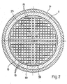
- the tubes 15 form a plurality of channels 18 (FIG. 2) which have a predetermined cross section.
- the walls of these channels 18 serve as settlement areas for microorganisms.
- the tubes 15 and thus also the channels 18 formed by them are arranged practically vertically in the reactor in the exemplary embodiment shown. Above the upper ends of the channels 18 there is the upper space 21 and below the lower ends of the channels 18 the lower space 23.
- the feed line 25 for the sewage sludge leads via the metering pump 24 and the valve 26 to the nozzle 29 of the distribution device 17.
- the discharge line 31 leads from the lower room 23 to the valve 33, to the extraction pump 28 and from there to a further part of the sludge treatment system.
- the valve 35 connects the line 31 via the circulating pump 27 to the Supply line 25. After closing the valves 26 and 33, the contents of the reactor can thus be circulated with the circulation pump 27.
- the gas which may arise during the biochemical reaction can be discharged via the gas outlet 32.
- the tube bundle 13 consists of the tubes 15 with a square cross section.
- These are advantageously plastic pipes with a cross section of more than 30 cm 2 .
- the cross section largely depends on the grain size of the substances contained in the sewage sludge.
- a cross-section of 64 cm 2 proved to be advantageous in the case of conventional sewage sludge.
- round or polygonal tubes could of course also be used.
- square tubes are commercially available at relatively low prices. Hexagonal pipes would be particularly cheap in terms of material consumption, but offer somewhat less settlement area than square pipes.
- the tubes are advantageously made of PVC or polyester and can have a high proportion of waste material and chalk, since they are not exposed to any particular hydraulic and mechanical stresses. This enables a cheap and also relatively light construction and offers no corrosion problems.
- the tube bundle can consist of several parts. As the drawing shows, the tube bundle 13 has a ring 37 and 38 made of an L-profile at the upper and lower edge. As can be seen from Figure 2, the ring 37 is reinforced by a reinforcing cross 39, which is formed from T-profiles. The tube bundle is further reinforced with annular bands 41 for easy assembly at intervals from the upper and lower edges.
- the rings 37, 38, the Reinforcement cross 39 and the bands 41 are expediently made of corrosion-resistant steel or steel with a coating that offers corrosion protection. Otherwise, the tubes 15 carry themselves through the chosen construction.
- the tube bundle 13 has a shape adapted to the reactor vessel 11. In large systems, tube bundle modules are advantageously available, with each module being dimensioned so that it can be easily transported and assembled.
- the distribution device 17 shown in FIGS. 1 and 3 has a nozzle 29 arranged at the end of the feed line 25.
- a baffle plate 40 is arranged at a distance from this nozzle 29, which is advantageously adjustable, which serves to discharge the nozzle 29 Distribute the beam evenly over the upper openings of the channels 18.
- the baffle plate 40 has a central opening 42 which is arranged at a predetermined distance from the roof 43 of the reactor vessel 11. However, it is also possible to provide a further baffle plate 44 above the baffle plate 40, in which case the distance of the baffle plate 40 from the roof 43 is not critical.
- part of the jet emerging from the nozzle 29 is deflected by the baffle plate 40, while another part of the beam passes through the opening 42 and hits the underside of the roof 43 or the baffle plate 44 and from there in particular into the channels 18 of the central area of the tube bundle 13 drips.
- the baffle plate 40 and a possibly provided second baffle plate 44 are carried by rods 45 which run conically from the nozzle 27 to the periphery of the baffle plate 40.
- the distribution device 17 consisting of Baffle plate 40 and possibly 44 and nozzle 29 is detachably fastened to the feed line 25 with a screw connection 47, for example a so-called milk pipe screw connection.
- a screw connection 47 for example a so-called milk pipe screw connection.
- adjustment means can be provided, for example a screw, in order to adjust the distance between the nozzle 29 and the baffle plate 40 and thus enable adjustment during assembly or later in operation.
- 13 hanging eyes 49 are arranged on the tube bundle, which allow the tube bundle 13 e.g. lower it with a crane into the finished container 11 or remove it again for maintenance work.
- the container 11 is expediently provided with a thermal insulation 51 and has an inspection opening 54 provided with a sight glass 53.
- Another opening 56 is located at the lower part of the container and is normally closed by the lid 55.
- a control device 58 is provided which is connected to a sensor 59, e.g. a pressure gauge, is connected and is used to keep constant and / or change the level in the reactor.
- control lines 61, 63 lead to the metering pump 24 and to the withdrawal pump 28. If both pumps 24, 28 have the same delivery volume per unit of time and work at the same time, the level in the reactor basically remains constant.
- the control device 58 can switch a pump 24, 28 on or off.
- the control device 58 can also serve to prevent blockage by lowering the liquid level in the reactor and then increasing it again at predetermined time intervals.
Abstract
Description
Die Erfindung betrifft einen Festbettreaktor zur Behandlung, insbesondere zur anaeroben Behandlung, von Klärschlamm oder mit organischen Stoffen stark belasteten Flüssigkeiten, mit einem Reaktorbehälter und einem im Reaktorbehälter angeordneten Festbett mit einer Vielzahl von praktisch senkrecht angeordneten Kanälen, deren Wandungen als Siedlungsflächen für Mikroorganismen dienen. Ein solcher Festbettreaktor wird in der US-PS 2 188 162 beschrieben, wo jedoch nur dessen Verwendung zur Reinigung von kommunalen Abwässern durch den Abbau von gelösten organischen Stoffen mittels aerober Bakterien beschrieben wird, nicht aber die Behandlung von Klärschlamm. Diese Literaturstelle erwähnt ausdrücklich, dass sich das Festbett immer unter dem Abwasserspiegel befindet. Bei der Würdigung dieser Literaturstelle wird in der DE-AS 24 20 745 bemerkt, dass die Strömungsgeschwindigkeiten in den verschiedenen Röhren sehr unterschiedlich seien. Die Oberflächen der Röhren kämen dabei nicht hinreichend gleichmässig zur Wirkung und es könnten sich auch tote Zonen bilden. Die DE-AS 24 20 745 schlägt daher Querverbindungen zwischen den einzelnen Kanälen vor. Dies hat aber den Nachteil,,dass dadurch nicht nur die Konstruktion des Festbettes verteuert wird, sondern dass die Wirbelbildung innerhalb der einzelnen Kanäle begünstigt wird. Eine solche Wirbelbildung ist jedoch für die Verwendung des Festbettreaktors in einer aneroben Stufe nicht erwünscht, weil dadurch die Wirksamkeit der Bakterien beeinträchtigt wird. In dieser Hinsicht kann auf die Publikation von C.F. Seyfried und M. Saake, "Abwasser und Schlammbehandlung, Fortschritte und Probleme", 15. Essener Tagung vom 10. bis 12. März 1982, hingewiesen werden. Dort wird ausdrücklich gefordert, dass der Klärschlamm in einem Festbsttreaktor eine möglichst geringe Umwälzung erfährt, weil acetogene und methanogene Bakterien in enger Symbiose existieren und daher sehr scherkraftempfindlich sind.The invention relates to a fixed bed reactor for treatment, in particular for anaerobic treatment, of sewage sludge or liquids heavily contaminated with organic substances, with a reactor vessel and a fixed bed arranged in the reactor vessel with a multiplicity of practically vertically arranged channels, the walls of which serve as settlement areas for microorganisms. Such a fixed bed reactor is described in US Pat. No. 2,188,162, where, however, only its use for the purification of municipal wastewater by the decomposition of dissolved organic substances by means of aerobic bacteria is described, but not the treatment of sewage sludge. This reference explicitly mentions that the fixed bed is always below the water level. When evaluating this reference, it is noted in DE-AS 24 20 745 that the flow velocities in the different tubes are very different. The surfaces of the tubes would not have a sufficiently uniform effect and dead zones could also form. DE-AS 24 20 745 therefore proposes cross-connections between the individual channels. However, this has the disadvantage, that this not only makes the construction of the fixed bed more expensive, but also favors the formation of eddies within the individual channels. However, such vortex formation is not desirable for the use of the fixed bed reactor in an anerobic stage, because it affects the effectiveness of the bacteria. In this regard, reference may be made to the publication by CF Seyfried and M. Saake, "Wastewater and Sludge Treatment, Advances and Problems", 15th Essen Conference from March 10th to 12th, 1982. There is explicitly requested that the sewage sludge undergoes the least possible upheaval in a Festbsttreaktor because acetogenic and methano g ene bacteria exist in close symbiosis and therefore are very shear-sensitive.
Die GB-OS 2 069 929 zeigt einen anerobischen Filter, bei dem Abwasser mittels eines Verteilers über ein Festbett bestehend aus Kunststoffringen oder alten Aluminiumbüchsen geleitet wird. Die Flüssigkeit tropft dann durch das Festbett hinunter und wird dann wieder rezirkuliert. Ein solcher Festbettreaktor hat jedoch den Nachteil, dass er insbesondere bei der in der betreffenden Literaturstelle nicht vorgesehenen Verwendung für den von Natur aus heterogen gearteten Klärschlamm rasch zu Verstopfung neigt. Wenn aber auch nur Teile des Reaktors verstopft sind,,führt dies zu einer Verminderung des wirksamen Volumens und dementsprechend muss sicherheitshalber eine lange Behandlungszeit vorgesehen werden. Nun ist es aber gerade das Ziel der Festbettreaktoren, die Behandlungszeit durch Schaffung grosser belebter Oberflächen zu verkürzen.GB-OS 2 069 929 shows an anerobic filter in which wastewater is passed through a distributor over a fixed bed consisting of plastic rings or old aluminum bushings. The liquid then drips down through the fixed bed and is then recirculated again. Such a fixed bed reactor has the disadvantage, however, that it tends to clog rapidly, especially when it is not intended for the naturally heterogeneous sewage sludge in the literature concerned. However, if only parts of the reactor are clogged, this leads to a reduction in the effective volume and, accordingly, a long treatment time must be provided for safety reasons. Now it is precisely the goal of the fixed bed reactors to shorten the treatment time by creating large, busy surfaces.
Es ist Aufgabe der vorliegenden Erfindung, einen verbesserten Festbettreaktor der eingangs erwähnten Art zu schaffen, der eine hohe Betriebssicherheit aufweist und ohne grössere Unterhaltsarbeiten die Behandlung von Klärschlamm oder mit organischen und/oder festen Stoffen stark belasteten Flüssigkeiten innert einer relativ kurzen Zeit erlaubt.It is an object of the present invention to provide an improved fixed-bed reactor of the type mentioned at the outset, which has a high level of operational reliability and allows the treatment of sewage sludge or liquids heavily contaminated with organic and / or solid substances within a relatively short time without major maintenance work.
Gemäss der Erfindung wird dies dadurch erreicht, dass eine über dem Festbett angeordnete Verteileinrichtung vorgesehen ist, welche die einzelnen Kanäle gleichmässig mit Klärschlamm oder Flüssigkeit beschickt, und dass Mittel zur Festlegung des Pegelstandes vorgesehen sind, welche den Füllpegel des Reaktors derart steuern, dass die einzelnen Kanäle nicht bis oben gefüllt sind. In einem solchen Festbettreaktor werden klar definierte Strömungsverhältnisse erreicht, die einer durch Ablagerungen bewirkten Querschnittsverminderung oder Verstopfung entgegenwirken. Dennoch bilden die Wandungen der einzelnen Kanäle grosse Siedlungsflächen für Mikroorganismen, so dass ein rascher Abbau des im Klärschlamm oder der Flüssigkeit enthaltenen Substanz erfolgt. Die einzelnen Kanäle sind während des Betriebs.in der Regel leicht zu überwachen, so dass bei einer dennoch eintretenden Verstopfung eines Kanals rasch zweckdienliche Massnahmen zu dessen Freilegung unternommen werden können. Ein wichtiger Vorteil des erfindungsgemässen Reaktors besteht auch darin, dass die Querschnittsverminderung in einem Kanal sich nicht auf den übrigen Teil des Reaktors schädigend auswirken kann. Es ist somit nicht mit Durchflussstörungen zu rechnen, wie sie bisher bei den üblichen Festbettreaktoren mit Kunststoffringen oder ähnlichem Füllmaterial auftraten. Da Mittel vorgesehen sind, welche den Füllpegel des Reaktors derart steuern, dass die einzelnen Kanäle nicht bis oben gefüllt sind, wird bei einer Verstopfung eines Kanals dieser mehr gefüllt als die übrigen Kanäle, so dass in diesem Kanal ein hydrostatischer Druck entsteht, der die Tendenz hat, den Kanal freizulegen. Wenn diese Freilegung nicht automatisch im Betrieb erfolgt, so kann der hydrostatische Druck im verstopften Kanal noch weiter erhöht werden, indem durch Abpumpen das Flüssigkeitsniveau im Reaktor gesenkt wird. Zu diesem Zwecke können die Mittel zur Festlegung des Pegelstandes durch eine Steuereinrichtung gebildet werden, mit der der Pegelstand konstant gehalten oder verändert werden kann. Wird das Flüssigkeitsniveau gesenkt, so wird dadurch der hydrostatische Druck im verstopften Kanal noch weiter erhöht, so dass dieser in den meisten Fällen freigelegt wird. Wenn dafür gesorgt wird, dass die Verteilvorrichtung bei niedrigem Flüssigkeitsniveau im Betrieb ist, so erfolgt ein Spülvorgang, bei dem die Wandungen der Kanäle gewaschen werden. Auch dadurch kann einer Verstopfung vorgebeugt werden. Es hat sich aber in der Praxis gezeigt, dass auch ohne eine solche Niveauabsenkung kaum eine Verstopfungsgefahr besteht, wenn der Querschnitt der Kanäle richtig dimensioniert und auch der Füllpegel des Reaktors richtig gewählt wird.According to the invention, this is achieved in that a distribution device is provided above the fixed bed, which uniformly feeds the individual channels with sewage sludge or liquid, and in that means are provided for determining the level which control the filling level of the reactor in such a way that the individual Channels are not filled to the top. In such a fixed bed reactor, clearly defined flow conditions are achieved which counteract a cross-sectional reduction or blockage caused by deposits. Nevertheless, the walls of the individual channels form large settlement areas for microorganisms, so that the substance contained in the sewage sludge or the liquid is broken down quickly. The individual channels are usually easy to monitor during operation, so that if a channel does become blocked, appropriate measures can be taken to expose it quickly. An important advantage of the reactor according to the invention is also that the reduction in cross section in one channel cannot have a damaging effect on the remaining part of the reactor. Flow disturbances such as have hitherto occurred in the conventional fixed bed reactors with plastic rings or similar filling material are therefore not to be expected. Since means are provided which determine the filling level of the reactor control that the individual channels are not filled to the top, if one channel becomes blocked, it is filled more than the other channels, so that hydrostatic pressure is generated in this channel, which tends to expose the channel. If this exposure is not carried out automatically during operation, the hydrostatic pressure in the blocked channel can be increased even further by lowering the liquid level in the reactor by pumping. For this purpose, the means for determining the level can be formed by a control device with which the level can be kept constant or changed. If the liquid level is lowered, the hydrostatic pressure in the blocked duct is increased further, so that it is exposed in most cases. If it is ensured that the distribution device is in operation when the liquid level is low, a rinsing process takes place in which the walls of the channels are washed. This can also prevent constipation. However, it has been shown in practice that even without such a lowering of the level there is hardly any risk of clogging if the cross-section of the channels is dimensioned correctly and the filling level of the reactor is also selected correctly.
Zweckmässigerweise wird der jeweilige Kanal durch ein Rohr gebildet. Dies ergibt eine einfache Konstruktion des Reaktors. Die Rohre weisen dabei vorteilhaft vieleckigen Querschnitt auf. Vorteilhaft ist ein rechteckiger Querschnitt, denn Rohre mit solchem Querschnitt sind im Handel.relativ billig erhältlich. Aus Gründen des geringsten Materialverbrauches werden vorteilhaft sechseckige Rohre gewählt. Sowohl bei vier- als auch bei sechseckigen Rohren ergeben sich keine unausgenützten Zwischenräume zwischen den Rohren. Die Rohre bestehen zweckmässigerweise aus Kunststoff. Es kann sich dabei um einen relativ billigen Kunststoff handeln, da sie keiner grösseren mechanischen Belastung ausgesetzt sind. Die Rohre können zu einem Bündel zusammengefasst sein, das sich in einem Arbeitsgang in den Reaktorbehälter absenken lässt. Bei grossen Reaktoren können auch mehrere separate Bündel vorgesehen werden. Das jeweilige Bündel oder wenigstens mehrere Rohre zusammen können in einem einzigen Arbeitsgang z.B. durch Extrudieren aus Kunststoff hergestellt werden. Vorteilhaft ist das Bündel am oberen und unteren Rand durch einen Ring aus einem L-Profil verstärkt. Das Bündel kann auch in Abständen vom oberen und unteren Rand mit ringförmigen Bändern weiter verstärkt sein. Um eine besonders sichere Lagerung der einzelnen Rohre zu gewährleisten, ist mindestens am unteren Ende des Bündels ein mit dem Ring verbundenes Verstärkungskreuz angeordnet. Von besonderer Bedeutung für das gute Funktionieren des Festbettreaktors ist die Verteileinrichtung. Gemäss einem Ausführungsbeispiel weist die Verteileinrichtung mindestens eine am Ende der Zuleitung angeordnete Düse und mindestens einen in Abstand von dieser Düse angeordneten Prallteller auf, welcher einen aus der Düse austretenden Strahl gleichmässig über die oberen Oeffnungen der Kanäle verteilt. Eine gleichmässige Beschickung der Kanäle ist von Bedeutung, damit in allen-Kanälen praktisch die gleiche Durchflussgeschwindigkeit herrscht. Diese sollte nur so gross sein, dass die an der Rohrwandung haftende Bakterienflora nicht gestört wird. Um eine möglichst gleichmässige Verteilung zu ermöglichen, weist der Prallteller ferner eine zentrale Oeffnung auf, wobei das Dach des Reaktorbehälters in einem vorbestimmten Abstand vom Prallteller angeordnet ist, damit durch die zentrale Oeffnung durchströmender Schlamm an der Innenwandung des Daches aufprallt und dadurch vorwiegend im zentralen Bereich des Rohrbündels verteilt wird. Es kann aber auch über dem genannten Prallteller ein weiterer Prallteller vorgesehen werden, falls das Dach zu hoch liegt.The respective channel is expediently formed by a tube. This results in a simple construction of the reactor. The tubes advantageously have a polygonal cross section. A rectangular cross-section is advantageous because pipes with such a cross-section are commercially available at relatively low prices. For reasons of the lowest material consumption, hexagonal tubes are advantageously chosen. With both square and hexagonal tubes, there are no unused gaps between the tubes. The pipes are expediently made of plastic. It can be a relatively cheap plastic, since they are not exposed to any major mechanical stress. The tubes can be combined into a bundle that can be lowered into the reactor vessel in one operation. In the case of large reactors, several separate bundles can also be provided. The respective bundle or at least several tubes together can be produced in a single operation, for example by extrusion from plastic. The bundle is advantageously reinforced at the top and bottom by a ring made of an L-profile. The bundle can also be further reinforced with annular bands at intervals from the upper and lower edges. In order to ensure a particularly secure storage of the individual tubes, a reinforcement cross connected to the ring is arranged at least at the lower end of the bundle. The distribution device is of particular importance for the good functioning of the fixed bed reactor. According to one embodiment, the distribution device has at least one nozzle arranged at the end of the feed line and at least one baffle plate arranged at a distance from this nozzle, which distributes a jet emerging from the nozzle evenly over the upper openings of the channels. Uniform feeding of the channels is important so that practically the same flow rate prevails in all channels. This should only be so large that the bacterial flora adhering to the tube wall is not disturbed. In order to enable a distribution that is as uniform as possible, the baffle plate also has a central opening, the roof of the reactor vessel being arranged at a predetermined distance from the baffle plate, so that sludge flowing through the central opening hits the inner wall of the roof and thereby predominantly in the central area of the tube bundle is distributed. However, a further baffle plate can also be provided above the baffle plate if the roof is too high.
Ein Ausführungsbeispiel der Erfindung sieht vor, dass die Zuleitung durch das Zentrum des Rohrbündels führt und dass der Prallteller vermittels Stäben an der Düse befestigt ist. Die Düse ist mit der Zuleitung mit einer leicht lösbaren Verschraubung, z.B. einer Milchrohrverschraubung, verbunden. Diese Ausgestaltung hat den Vorteil, dass die Verteileinrichtung und Rohrbündel eine praktische Einheit bilden, die leicht lösbar ist und es ermöglicht, die Funktion des Pralltellers bereits ausserhalb des Reaktors oder bei offenem Reaktordach auszuprobieren. Gegenüber einer Anordnung des - Pralltellers am Reaktordach hat dies auch den Vorteil, dass eine genaue Zentrierung von Düse und Prallteller von allem Anfang an gewährleistet ist. Die Stäbe führen vorteilhaft von der Düse her konisch zur Peripherie des Pralltellers. Allfällig an den Stäben anhaftendes faseriges Material rutscht dann nach Abstellen des Schlammstromes an den Stäben zur Düse hinunter und wird beim erneuten Einschalten vom Strahl weggeschleudert. Dieser Effekt tritt automatisch auf, wenn eine entsprechende Steuereinrichtung für einen Spülvorgang vorgesehen wird. Die Praxis hat gezeigt, dass durch die beschriebene Konstruktion eine weitgehende Selbstreinigung erzielt wird.An embodiment of the invention provides that the feed line leads through the center of the tube bundle and that the baffle plate is attached to the nozzle by means of rods. The nozzle is connected to the supply line with an easily detachable screw connection, e.g. a milk pipe connection. This configuration has the advantage that the distribution device and tube bundle form a practical unit that is easily detachable and makes it possible to try out the function of the baffle plate outside of the reactor or with the reactor roof open. Compared to an arrangement of the baffle plate on the reactor roof, this also has the advantage that precise centering of the nozzle and baffle plate is guaranteed from the very beginning. The rods advantageously lead conically from the nozzle to the periphery of the baffle plate. Any fibrous material adhering to the rods then slides down to the nozzle after the flow of sludge has been switched off and is thrown away by the jet when switched on again. This effect occurs automatically if a corresponding control device is provided for a rinsing process. Practice has shown that the construction described achieves extensive self-cleaning.
Vorteilhaft ist die Distanz zwischen Düse und mindestens einem der Prallteller regulierbar. Dadurch ist es möglich, bei Inbetriebnahme des Reaktors oder auch noch später die Schlammverteilung zu regulieren.The distance between the nozzle and at least one of the baffle plates is advantageously adjustable. This makes it possible to regulate the sludge distribution when starting up the reactor or even later.
Zweckmässigerweise ist eine Steuereinrichtung zum Konstanthalten und/oder Verändern des Pegelstandes vorgesehen. Diese Steuereinrichtung kann als Teil der Verteileinrichtung betrachtet werden, denn um eine gute Verteilung zu ermöglichen, sollte der Pegelstand der Flüssigkeit im Reaktor um einiges tiefer sein als das obere Ende der Kanäle. Diese Steuereinrichtung kann derart ausgebildet sein, dass sie in vorbestimmten Zeitabständen das Flüssigkeitsniveau im Reaktor absenkt und dann wieder erhöht. Dadurch wird, wie bereits vorher erwähnt, einer Verstopfung vorgebeugt. Die Erfindung betrifft auch die Verwendung des Festbettreaktors als Stufe in einem mehrstufigen Behandlungsverfahren für Klärschlamm oder mit organischen Stoffen hoch belasteten Flüssigkeiten. Für diese Verwendung ist der erfindungsgemässe Festbettreaktor besonders gut geeignet, da er weitgehend verstopfungssicher ist. Des weiteren treten im Betrieb keine hohen Scherkräfte auf, welche die biochemischen Vorgänge stören könnten. Als besonders vorteilhaft erweist sich der Reaktor als Versäuerungsreaktor. Der erfindungsgemässe Aufbau ermöglicht eine kleine Dimensionierung, was es sogar möglich macht, den Versäuerungsreaktor in einen bestehenden Faulturm einzubauen, wo er bloss einen kleinen Bruchteil des Faulturmvolumens beansprucht. Der erfindungsgemässe Reaktor lässt sich aber auch als Acetat-und/oder Methanisierungsreaktor verwenden. Seine Verwendung ist aber nicht auf anaerobe Verfahren beschränkt, sondern bei geeigneter Ausführung lässt er sich auch für aerobe Verfahren verwenden, wie beispielsweise das sogenannte "AEROTHERM-Verfahren", das in der europäischen Patentanmeldung Nr. 81109992.8 "Verfahren zur biologischen Wärmeerzeugung" beschrieben ist.A control device for keeping the level constant and / or changing the level is expediently provided. This control device can be regarded as part of the distribution device, because in order to enable a good distribution, the level of the liquid in the reactor should be quite a bit be deeper than the top of the channels. This control device can be designed such that it lowers the liquid level in the reactor and then increases it again at predetermined time intervals. As mentioned before, this prevents constipation. The invention also relates to the use of the fixed bed reactor as a stage in a multi-stage treatment process for sewage sludge or liquids which are highly contaminated with organic substances. The fixed bed reactor according to the invention is particularly well suited for this use, since it is largely resistant to clogging. Furthermore, there are no high shear forces during operation that could interfere with the biochemical processes. The reactor proves to be particularly advantageous as an acidification reactor. The construction according to the invention enables a small dimensioning, which even makes it possible to install the acidification reactor in an existing digestion tower, where it only takes up a small fraction of the digestion tower volume. However, the reactor according to the invention can also be used as an acetate and / or methanation reactor. However, its use is not limited to anaerobic processes, but if suitably carried out it can also be used for aerobic processes, such as the so-called "AEROTHERM process", which is described in European patent application No. 81109992.8 "Process for biological heat generation".
Ausführungsbeispiele der Erfindung werden nun unter Bezugnahme auf die Zeichnung beschrieben. Es zeigt:
- Fig. 1 ein erstes Ausführungsbeispiel eines Festbettreaktors im Schnitt, wobei jedoch das Rohrbündel nicht geschnitten ist,
- Fig. 2 einen Schnitt durch den Festbettreaktor entlang der Linie II-II von Figur 1,
- Fig. 3 eine Seitenansicht der Verteileinrichtung und
- 1 shows a first embodiment of a fixed bed reactor in section, but the tube bundle is not cut,
- 2 shows a section through the fixed bed reactor along the line II-II of FIG. 1,
- Fig. 3 is a side view of the distribution device and
Das in den Figuren 1 bis 3 gezeigte Ausführungsbeispiel eines Festbettreaktors eignet sich insbesondere zur anaeroben Behandlung von Klärschlamm oder mit organischen Stoffen stark belasteten Flüssigkeiten. Er kann als Versäuerungsreaktor, Acetatreaktor und/oder Methanreaktor verwendet werden. Wie Figur 1 zeigt, besteht der Festbettreaktor im wesentlichen aus einem Behälter 11, in welchem ein Rohrbündel 13 angeordnet ist, dessen Rohre 15 durch eine Verteileinrichtung 17 mit Klärschlamm oder mit organischen Stoffen stark belasteten Flüssigkeiten beschickt werden. Die Rohre 15 bilden eine Vielzahl von Kanälen 18 (Fig. 2), welche einen vorbestimmten Querschnitt aufweisen. Die Wandungen dieser Kanäle 18 dienen als Siedlungsflächen für Mikroorganismen. Die Rohre 15 und somit auch die durch sie gebildeten Kanäle 18 sind beim gezeigten Ausführungsbeispiel praktisch senkrecht im Reaktor angeordnet. Ueber den oberen Enden der Kanäle 18 befindet sich der obere Raum 21 und unter den unteren Enden der Kanäle 18 der untere Raum 23. Die Zuleitung 25 für den Klärschlamm führt über die Dosierpumpe 24 und das Ventil 26 zur Düse 29 der Verteileinrichtung 17. Die Ableitung 31 führt vom unteren Raum 23 zum Ventil 33, zur Entnahmepumpe 28 und von dort zu einem weiteren Teil der Schlammbehandlungsanlage. Um eine Umwälzung des Reaktorinhalts zu ermöglichen, verbindet das Ventil 35 die Leitung 31 über die Umwälzpumpe 27 mit der Zuleitung 25. Nach dem Schliessen der Ventil 26 und 33 kann somit der Inhalt des Reaktors mit der Umwälzpumpe 27 umgewälzt werden. Das bei der biochemischen Reaktion gegebenenfalls entstehende Gas kann über den Gasabzug 32 abgeleitet werden.The embodiment of a fixed bed reactor shown in FIGS. 1 to 3 is particularly suitable for the anaerobic treatment of sewage sludge or liquids heavily contaminated with organic substances. It can be used as an acidification reactor, acetate reactor and / or methane reactor. As FIG. 1 shows, the fixed bed reactor essentially consists of a
Betrachtet man nun das Rohrbündel 13 gemäss den Figuren 1 und 2, so ist ersichtlich, dass es beim gezeigten Ausführungsbeispiel aus den Rohren 15 mit viereckigem Querschnitt besteht. Dabei handelt es sich vorteilhaft um Kunststoffrohre mit einem Querschnitt von mehr als 30 cm2. Der Querschnitt ist weitgehend abhängig von der Korngrösse der im Klärschlamm enthaltenen Stoffe. Als vorteilhaft erwies sich beim üblichen Klärschlamm ein Querschnitt von 64 cm2. Statt viereckige Rohre könnten natürlich auch runde oder vieleckige Rohre verwendet werden. Viereckige Rohre sind aber im Handel zu relativ günstigen Preisen erhältlich. Sechseckige Rohre wären vom Materialverbrauch her besonders günstig, bieten aber etwas weniger Siedlungsfläche als viereckige Rohre. Die-Rohre bestehen vorteilhaft aus PVC oder Polyester und können einen hohen Altmaterial-und Kreideanteil aufweisen., da sie keinen besonderen hydraulischen und mechanischen Beanspruchungen ausgesetzt sind. Dies ermöglicht eine billige und auch relativ leichte Konstruktion und bietet keine Korrosionsprobleme. Bei grossen Reaktoren kann das Rohrbündel aus mehreren Teilen bestehen. Wie die Zeichnung zeigt, weist das Rohrbündel 13 am oberen und unteren Rand einen Ring 37 und 38 aus einem L-Profil auf. Wie aus Figur 2 ersichtlich, ist der Ring 37 durch ein Verstärkungskreuz 39, das aus T-Profilen gebildet ist, verstärkt. Das Rohrbündel ist ferner für die einfache Montage in Abständen vom oberen und unteren Rand mit ringförmigen Bändern 41 verstärkt. Die Ringe 37, 38, das Verstärkungskreuz 39 und die Bänder 41 bestehen zweckmässigerweise aus korrosionsfestem Stahl oder Stahl mit einer korrosionsschutzbietenden Beschichtung. Im übrigen tragen sich die Rohre 15 durch die gewählte Konstruktion selbst. Das Rohrbündel 13 besitzt eine dem Reaktorbehälter 11 angepasste Form. Bei Grossanlagen sind vorteilhaft Rohrbündelmodule vorhanden, wobei jedes Modul so bemessen wird, dass es leicht transportiert und montiert werden kann.If one now looks at the
Die in den Figuren 1 und 3 ersichtliche Verteileinrichtung 17 besitzt eine am Ende der Zuleitung 25 angeordnete Düse 29. In einem Abstand von dieser Düse 29, der vorteilhaft verstellbar ist, ist ein Prallteller 40 angeordnet, der dazu dient, den aus der Düse 29 austretenden Strahl gleichmässig über die oberen Oeffnungen der Kanäle 18 zu verteilen. Der Prallteller 40 weist eine zentrale Oeffnung 42 auf, die in einem vorbestimmten Abstand vom Dach 43 des Reaktorbehälters 11 angeordnet ist. Es ist aber auch möglich, über dem Prallteller 40 einen weiteren Prallteller 44 vorzusehen, in welchem Falle der Abstand des Pralltellers 40 vom Dach 43 unkritisch ist. Im Betrieb wird ein Teil des aus der Düse 29 austretenden Strahles vom Prallteller 40 abgelenkt, während ein anderer Teil des Strahles durch die Oeffnung 42 durchtritt und an die Unterseite des Daches 43 oder an den Prallteller 44 aufschlägt und von dort insbesondere in die Kanäle 18 des zentralen Bereichs des Rohrbündels 13 tropft. Wie Figur 3 zeigt, wird der Prallteller 40 sowie ein eventuell vorgesehener zweiter Prallteller 44-durch Stäbe 45 getragen, die konisch von der Düse 27 her zur Peripherie des Pralltellers 40 laufen. Diese Anordnung hat sich als sehr betriebssicher erwiesen, weil faseriges Material zur Düse 29 hinunterrutschen kann, wenn aus dieser.kein Strahl austritt. Sobald wieder ein Strahl aus der Düse 29 tritt, wird das' faserige Material weggeschleudert. Die Verteileinrichtung 17 bestehend aus Prallteller 40 und eventuell 44 und Düse 29 ist mit einer Verschraubung 47, z.B. einer sogenannten Milchrohrverschraubung,abnehmbar an der Zuleitung 25 befestigt. Es sind verschiedene Ausgestaltungen der Düse 29 möglich, so können beispielsweise Verstellmittel vorgesehen sind, z.B. eine Schraube, um die Distanz zwischen Düse 29 und Prallteller 40 zu verstellen und so eine Justage bei der Montage oder später im Betrieb zu ermöglichen.The
Wie Figur 1 zeigt, sind am Rohrbündel 13 Aufhängeösen 49 angeordnet, welche es erlauben, das Rohrbündel 13 z.B. mit einem Kran in den fertigen Behälter 11 abzusenken oder diesem zu Unterhaltsarbeiten wieder zu entnehmen. Der Behälter 11 ist zweckmässigerweise mit einer thermischen Isolation 51 versehen und weist eine mit einem Schauglas 53 versehene Inspektionsöffnung 54 auf. Eine weitere Oeffnung 56 befindet sich am unteren Teil des Behälters und ist normalerweise durch den Deckel 55 verschlossen.As Figure 1 shows, 13 hanging
In Figur 1 ist eine Steuereinrichtung 58 vorgesehen, die an einen Sensor 59, z.B. ein Manometer, angeschlossen ist und dem Konstanthalten und/oder Verändern des Pegelstandes im Reaktor dient. Zu diesem Zwecke führen Steuerleitungen 61, 63 zur Dosierpumpe 24 und zur Entnahmepumpe 28. Wenn beide Pumpen 24, 28 das gleiche Fördervolumen pro Zeiteinheit haben und gleichzeitig arbeiten, so bleibt der Pegelstand im Reaktor grundsätzlich konstant. Bei einer unerwünschten Aenderung des Pegelstandes kann die Steuereinrichtung 58 eine Pumpe 24, 28 ein- oder abschalten. Die Steuereinrichtung 58 kann auch dazu dienen, einer Verstopfung vorzubeugen, indem sie in vorbestimmten Zeitabständen das Flüssigkeitsniveau im Reaktor absenkt und dann wieder erhöht.In Figure 1, a
Claims (26)
Priority Applications (1)
| Application Number | Priority Date | Filing Date | Title |
|---|---|---|---|
| AT83107273T ATE17468T1 (en) | 1982-08-06 | 1983-07-25 | FIXED BED REACTOR FOR THE TREATMENT, ESPECIALLY FOR ANAEROBIC TREATMENT, OF SEWAGE SLUDGE OR LIQUIDS HEAVY LOADED WITH ORGANIC SUBSTANCES. |
Applications Claiming Priority (2)
| Application Number | Priority Date | Filing Date | Title |
|---|---|---|---|
| CH474482 | 1982-08-06 | ||
| CH4744/82 | 1982-08-06 |
Publications (2)
| Publication Number | Publication Date |
|---|---|
| EP0100953A1 true EP0100953A1 (en) | 1984-02-22 |
| EP0100953B1 EP0100953B1 (en) | 1986-01-15 |
Family
ID=4281758
Family Applications (1)
| Application Number | Title | Priority Date | Filing Date |
|---|---|---|---|
| EP19830107273 Expired EP0100953B1 (en) | 1982-08-06 | 1983-07-25 | Fixed bed reactor for the treatment, especially the anaerobic treatment of sewage sludge or liquids heavily polluted with organic compounds |
Country Status (5)
| Country | Link |
|---|---|
| US (1) | US4488960A (en) |
| EP (1) | EP0100953B1 (en) |
| AT (1) | ATE17468T1 (en) |
| BR (1) | BR8304206A (en) |
| DE (1) | DE3361853D1 (en) |
Cited By (2)
| Publication number | Priority date | Publication date | Assignee | Title |
|---|---|---|---|---|
| EP0208303A2 (en) * | 1985-07-12 | 1987-01-14 | Linde Aktiengesellschaft | Process and apparatus for the anaerobic biological treatment of organic polluted liquids and/or liquid-solid mixtures |
| EP1849750A1 (en) * | 2006-04-04 | 2007-10-31 | Technoindustrie S.A. | Installation and process for waste water treatment with a tubular, vertical reactor |
Families Citing this family (4)
| Publication number | Priority date | Publication date | Assignee | Title |
|---|---|---|---|---|
| JPS6369590A (en) * | 1986-09-11 | 1988-03-29 | Iseki Kaihatsu Koki:Kk | Purifier |
| DE4118927A1 (en) * | 1991-06-08 | 1992-12-10 | Mesroc Gmbh | FIXED BED REACTOR FOR THE BIOLOGICAL TREATMENT OF SEWAGE |
| CA2792439A1 (en) * | 2001-05-31 | 2002-12-19 | Veolia Water Solutions & Technologies Support | Anaerobic digestion apparatus, methods for anaerobic digestion and for minimizing the use of inhibitory polymers in digestion |
| RU2700490C1 (en) * | 2018-10-25 | 2019-09-17 | Общество с ограниченной ответственностью "Эволюция Биогазовых Систем" | Bioreactor plant for anaerobic treatment of organic wastes of animal and vegetable origin to produce organic fertilizers and biogas |
Citations (6)
| Publication number | Priority date | Publication date | Assignee | Title |
|---|---|---|---|---|
| US1674480A (en) * | 1927-09-10 | 1928-06-19 | A M Lockett & Company Ltd | Spray nozzle |
| US2188162A (en) * | 1938-02-21 | 1940-01-23 | Henry B Schulhoff | Sewage treatment |
| US3189283A (en) * | 1963-01-07 | 1965-06-15 | John R Moore | Spray head |
| FR1590954A (en) * | 1967-11-08 | 1970-04-20 | ||
| DE2420745A1 (en) * | 1974-04-29 | 1975-10-30 | Ishigaki Mech Ind | Biological sewage clarification - by aeration and flocculation on plastic tube bundles regenerated by reverse flushing |
| GB2068929A (en) * | 1980-02-06 | 1981-08-19 | Celanese Corp | Biological filter and process |
Family Cites Families (7)
| Publication number | Priority date | Publication date | Assignee | Title |
|---|---|---|---|---|
| FR2131092A6 (en) * | 1971-01-14 | 1972-11-10 | Bergmann Tech | |
| JPS5017049A (en) * | 1973-06-20 | 1975-02-22 | ||
| US4045344A (en) * | 1974-04-29 | 1977-08-30 | Ishigaki Kiko Co., Ltd. | Apparatus for treating waste water |
| US3966604A (en) * | 1975-03-25 | 1976-06-29 | Diggs Richard E | Apparatus for aerobic decomposition of sewage |
| US4028246A (en) * | 1975-11-20 | 1977-06-07 | Lund Norman S | Liquid purification system |
| US4192746A (en) * | 1978-05-24 | 1980-03-11 | Arvanitakis Kostas S | Liquid clarification system |
| US4246114A (en) * | 1978-11-15 | 1981-01-20 | Multi-Flo, Inc. | Aerobic waste treatment package |
-
1983
- 1983-07-25 AT AT83107273T patent/ATE17468T1/en not_active IP Right Cessation
- 1983-07-25 EP EP19830107273 patent/EP0100953B1/en not_active Expired
- 1983-07-25 DE DE8383107273T patent/DE3361853D1/en not_active Expired
- 1983-08-02 US US06/519,693 patent/US4488960A/en not_active Expired - Lifetime
- 1983-08-05 BR BR8304206A patent/BR8304206A/en unknown
Patent Citations (6)
| Publication number | Priority date | Publication date | Assignee | Title |
|---|---|---|---|---|
| US1674480A (en) * | 1927-09-10 | 1928-06-19 | A M Lockett & Company Ltd | Spray nozzle |
| US2188162A (en) * | 1938-02-21 | 1940-01-23 | Henry B Schulhoff | Sewage treatment |
| US3189283A (en) * | 1963-01-07 | 1965-06-15 | John R Moore | Spray head |
| FR1590954A (en) * | 1967-11-08 | 1970-04-20 | ||
| DE2420745A1 (en) * | 1974-04-29 | 1975-10-30 | Ishigaki Mech Ind | Biological sewage clarification - by aeration and flocculation on plastic tube bundles regenerated by reverse flushing |
| GB2068929A (en) * | 1980-02-06 | 1981-08-19 | Celanese Corp | Biological filter and process |
Cited By (3)
| Publication number | Priority date | Publication date | Assignee | Title |
|---|---|---|---|---|
| EP0208303A2 (en) * | 1985-07-12 | 1987-01-14 | Linde Aktiengesellschaft | Process and apparatus for the anaerobic biological treatment of organic polluted liquids and/or liquid-solid mixtures |
| EP0208303A3 (en) * | 1985-07-12 | 1988-06-01 | Linde Aktiengesellschaft | Process and apparatus for the anaerobic biological treatment of organic polluted liquids and/or liquid-solid mixtures |
| EP1849750A1 (en) * | 2006-04-04 | 2007-10-31 | Technoindustrie S.A. | Installation and process for waste water treatment with a tubular, vertical reactor |
Also Published As
| Publication number | Publication date |
|---|---|
| US4488960A (en) | 1984-12-18 |
| EP0100953B1 (en) | 1986-01-15 |
| DE3361853D1 (en) | 1986-02-27 |
| BR8304206A (en) | 1984-03-13 |
| ATE17468T1 (en) | 1986-02-15 |
Similar Documents
| Publication | Publication Date | Title |
|---|---|---|
| EP0153299B1 (en) | Process and plant for the anaerobic treatment of organic substrates | |
| EP2041035B1 (en) | Reactor comprising a supply distribution system for anaerobic waste water treatment | |
| WO2008099227A1 (en) | Method and device for producing biogas from a biomass | |
| DE3239304A1 (en) | Reactor for producing biogas from liquid manure | |
| EP0100953B1 (en) | Fixed bed reactor for the treatment, especially the anaerobic treatment of sewage sludge or liquids heavily polluted with organic compounds | |
| EP0303149B1 (en) | Fixed-bed loop reactor for an ascending flow | |
| EP1996318B1 (en) | Loop reactor with blockage-resistant gas distribution | |
| DE1904206A1 (en) | Plant for wastewater treatment through flocculation and activation | |
| EP1657222B1 (en) | Method and apparatus for biological treatment of a suspension in a bioreactor. | |
| DE3330696A1 (en) | PLANT FOR ANAEROBIC DEGRADATION OF ORGANIC SUBSTRATES | |
| DE3326879A1 (en) | Biogas reactor | |
| DE112020005266T5 (en) | Anaerobic fermentation apparatus for the production of biogas from organic solids | |
| DE2420744C3 (en) | Device for purifying waste water | |
| DE202009017869U1 (en) | Device for separating gaseous, liquid and solid substances in a bioreactor | |
| EP0058247B1 (en) | Process and apparatus for the anaerobic purification of liquids containing organic substances | |
| DE19951194A1 (en) | Multi-purpose shaft, small sewage treatment plant and wastewater treatment process | |
| EP1588987B1 (en) | Water treatment plant having concentric basins | |
| DE10155760B4 (en) | Process for in situ deacidification of sulfuric acid water | |
| DE3324072C2 (en) | Device for anaerobic wastewater treatment | |
| DE102005028433A1 (en) | Fixed bed reactor for the anaerobic treatment of waste water | |
| EP0575294A1 (en) | Process for preparing-hydrolytically stable trivalent phosphorus compounds and their use as stabilisators for thermoplastic materials | |
| EP0121729B1 (en) | High performance run-through biological reactor | |
| AT401171B (en) | Apparatus for the anaerobic treatment of organic substrates | |
| DE10335961B4 (en) | Apparatus and method for anaerobic purification of wastewater | |
| EP1493717A1 (en) | Method for flushing a biological sewage treatment reactor |
Legal Events
| Date | Code | Title | Description |
|---|---|---|---|
| PUAI | Public reference made under article 153(3) epc to a published international application that has entered the european phase |
Free format text: ORIGINAL CODE: 0009012 |
|
| 17P | Request for examination filed |
Effective date: 19831212 |
|
| AK | Designated contracting states |
Designated state(s): AT BE CH DE FR GB IT LI LU NL SE |
|
| GRAA | (expected) grant |
Free format text: ORIGINAL CODE: 0009210 |
|
| AK | Designated contracting states |
Designated state(s): AT BE CH DE FR GB IT LI LU NL SE |
|
| REF | Corresponds to: |
Ref document number: 17468 Country of ref document: AT Date of ref document: 19860215 Kind code of ref document: T |
|
| ITF | It: translation for a ep patent filed |
Owner name: ING. C. GREGORJ S.P.A. |
|
| REF | Corresponds to: |
Ref document number: 3361853 Country of ref document: DE Date of ref document: 19860227 |
|
| ET | Fr: translation filed | ||
| PLBE | No opposition filed within time limit |
Free format text: ORIGINAL CODE: 0009261 |
|
| STAA | Information on the status of an ep patent application or granted ep patent |
Free format text: STATUS: NO OPPOSITION FILED WITHIN TIME LIMIT |
|
| 26N | No opposition filed | ||
| PGFP | Annual fee paid to national office [announced via postgrant information from national office to epo] |
Ref country code: SE Payment date: 19910702 Year of fee payment: 9 |
|
| PGFP | Annual fee paid to national office [announced via postgrant information from national office to epo] |
Ref country code: LU Payment date: 19910703 Year of fee payment: 9 |
|
| PGFP | Annual fee paid to national office [announced via postgrant information from national office to epo] |
Ref country code: AT Payment date: 19910725 Year of fee payment: 9 |
|
| ITTA | It: last paid annual fee | ||
| PGFP | Annual fee paid to national office [announced via postgrant information from national office to epo] |
Ref country code: NL Payment date: 19910731 Year of fee payment: 9 Ref country code: FR Payment date: 19910731 Year of fee payment: 9 Ref country code: BE Payment date: 19910731 Year of fee payment: 9 |
|
| EPTA | Lu: last paid annual fee | ||
| PGFP | Annual fee paid to national office [announced via postgrant information from national office to epo] |
Ref country code: GB Payment date: 19920706 Year of fee payment: 10 |
|
| PG25 | Lapsed in a contracting state [announced via postgrant information from national office to epo] |
Ref country code: LU Free format text: LAPSE BECAUSE OF NON-PAYMENT OF DUE FEES Effective date: 19920725 Ref country code: AT Effective date: 19920725 |
|
| PG25 | Lapsed in a contracting state [announced via postgrant information from national office to epo] |
Ref country code: SE Effective date: 19920726 |
|
| PG25 | Lapsed in a contracting state [announced via postgrant information from national office to epo] |
Ref country code: BE Effective date: 19920731 |
|
| BERE | Be: lapsed |
Owner name: UTB UMWELTTECHNIK BUCHS A.G. Effective date: 19920731 |
|
| PG25 | Lapsed in a contracting state [announced via postgrant information from national office to epo] |
Ref country code: NL Effective date: 19930201 |
|
| NLV4 | Nl: lapsed or anulled due to non-payment of the annual fee | ||
| PG25 | Lapsed in a contracting state [announced via postgrant information from national office to epo] |
Ref country code: FR Effective date: 19930331 |
|
| REG | Reference to a national code |
Ref country code: FR Ref legal event code: ST |
|
| PG25 | Lapsed in a contracting state [announced via postgrant information from national office to epo] |
Ref country code: GB Effective date: 19930725 |
|
| GBPC | Gb: european patent ceased through non-payment of renewal fee |
Effective date: 19930725 |
|
| EUG | Se: european patent has lapsed |
Ref document number: 83107273.1 Effective date: 19930204 |
|
| PGFP | Annual fee paid to national office [announced via postgrant information from national office to epo] |
Ref country code: CH Payment date: 19970717 Year of fee payment: 15 |
|
| PGFP | Annual fee paid to national office [announced via postgrant information from national office to epo] |
Ref country code: DE Payment date: 19970827 Year of fee payment: 15 |
|
| PG25 | Lapsed in a contracting state [announced via postgrant information from national office to epo] |
Ref country code: LI Free format text: LAPSE BECAUSE OF NON-PAYMENT OF DUE FEES Effective date: 19980731 Ref country code: CH Free format text: LAPSE BECAUSE OF NON-PAYMENT OF DUE FEES Effective date: 19980731 |
|
| REG | Reference to a national code |
Ref country code: CH Ref legal event code: PL |
|
| PG25 | Lapsed in a contracting state [announced via postgrant information from national office to epo] |
Ref country code: DE Free format text: LAPSE BECAUSE OF NON-PAYMENT OF DUE FEES Effective date: 19990501 |