EP0806280A2 - Dispositif et installation pour la préparation des matières plastiques - Google Patents
Dispositif et installation pour la préparation des matières plastiques Download PDFInfo
- Publication number
- EP0806280A2 EP0806280A2 EP97890072A EP97890072A EP0806280A2 EP 0806280 A2 EP0806280 A2 EP 0806280A2 EP 97890072 A EP97890072 A EP 97890072A EP 97890072 A EP97890072 A EP 97890072A EP 0806280 A2 EP0806280 A2 EP 0806280A2
- Authority
- EP
- European Patent Office
- Prior art keywords
- screw
- extruder
- plastic material
- discharge opening
- screws
- Prior art date
- Legal status (The legal status is an assumption and is not a legal conclusion. Google has not performed a legal analysis and makes no representation as to the accuracy of the status listed.)
- Granted
Links
- 239000004033 plastic Substances 0.000 title claims abstract description 70
- 229920003023 plastic Polymers 0.000 title claims abstract description 70
- 238000012545 processing Methods 0.000 title claims description 25
- 239000000463 material Substances 0.000 claims abstract description 77
- 229920001169 thermoplastic Polymers 0.000 claims abstract description 10
- 239000004416 thermosoftening plastic Substances 0.000 claims abstract description 10
- 230000007423 decrease Effects 0.000 claims description 8
- 230000001105 regulatory effect Effects 0.000 claims description 7
- 230000009467 reduction Effects 0.000 claims description 6
- 230000001154 acute effect Effects 0.000 claims description 3
- 230000010006 flight Effects 0.000 claims 1
- 230000006835 compression Effects 0.000 abstract description 6
- 238000007906 compression Methods 0.000 abstract description 6
- 238000002360 preparation method Methods 0.000 abstract description 5
- 230000000694 effects Effects 0.000 description 5
- 238000010276 construction Methods 0.000 description 3
- 238000002156 mixing Methods 0.000 description 3
- 238000012856 packing Methods 0.000 description 3
- 239000013502 plastic waste Substances 0.000 description 3
- 238000005406 washing Methods 0.000 description 3
- 230000009471 action Effects 0.000 description 2
- 238000004898 kneading Methods 0.000 description 2
- 239000007788 liquid Substances 0.000 description 2
- 239000000203 mixture Substances 0.000 description 2
- 230000032258 transport Effects 0.000 description 2
- 241000237858 Gastropoda Species 0.000 description 1
- 238000005054 agglomeration Methods 0.000 description 1
- 230000002776 aggregation Effects 0.000 description 1
- 230000008901 benefit Effects 0.000 description 1
- 230000033228 biological regulation Effects 0.000 description 1
- 238000005056 compaction Methods 0.000 description 1
- 230000003247 decreasing effect Effects 0.000 description 1
- 238000013461 design Methods 0.000 description 1
- 230000008030 elimination Effects 0.000 description 1
- 238000003379 elimination reaction Methods 0.000 description 1
- 230000001050 lubricating effect Effects 0.000 description 1
- 238000012423 maintenance Methods 0.000 description 1
- 238000004519 manufacturing process Methods 0.000 description 1
- 239000000155 melt Substances 0.000 description 1
- 238000000034 method Methods 0.000 description 1
- 230000008569 process Effects 0.000 description 1
- 238000011144 upstream manufacturing Methods 0.000 description 1
- 239000002699 waste material Substances 0.000 description 1
Images


Classifications
-
- B—PERFORMING OPERATIONS; TRANSPORTING
- B30—PRESSES
- B30B—PRESSES IN GENERAL
- B30B15/00—Details of, or accessories for, presses; Auxiliary measures in connection with pressing
- B30B15/30—Feeding material to presses
- B30B15/302—Feeding material in particulate or plastic state to moulding presses
- B30B15/308—Feeding material in particulate or plastic state to moulding presses in a continuous manner, e.g. for roller presses, screw extrusion presses
-
- B—PERFORMING OPERATIONS; TRANSPORTING
- B29—WORKING OF PLASTICS; WORKING OF SUBSTANCES IN A PLASTIC STATE IN GENERAL
- B29B—PREPARATION OR PRETREATMENT OF THE MATERIAL TO BE SHAPED; MAKING GRANULES OR PREFORMS; RECOVERY OF PLASTICS OR OTHER CONSTITUENTS OF WASTE MATERIAL CONTAINING PLASTICS
- B29B17/00—Recovery of plastics or other constituents of waste material containing plastics
- B29B17/0026—Recovery of plastics or other constituents of waste material containing plastics by agglomeration or compacting
-
- B—PERFORMING OPERATIONS; TRANSPORTING
- B29—WORKING OF PLASTICS; WORKING OF SUBSTANCES IN A PLASTIC STATE IN GENERAL
- B29B—PREPARATION OR PRETREATMENT OF THE MATERIAL TO BE SHAPED; MAKING GRANULES OR PREFORMS; RECOVERY OF PLASTICS OR OTHER CONSTITUENTS OF WASTE MATERIAL CONTAINING PLASTICS
- B29B7/00—Mixing; Kneading
- B29B7/30—Mixing; Kneading continuous, with mechanical mixing or kneading devices
- B29B7/34—Mixing; Kneading continuous, with mechanical mixing or kneading devices with movable mixing or kneading devices
- B29B7/38—Mixing; Kneading continuous, with mechanical mixing or kneading devices with movable mixing or kneading devices rotary
- B29B7/40—Mixing; Kneading continuous, with mechanical mixing or kneading devices with movable mixing or kneading devices rotary with single shaft
- B29B7/42—Mixing; Kneading continuous, with mechanical mixing or kneading devices with movable mixing or kneading devices rotary with single shaft with screw or helix
- B29B7/422—Mixing; Kneading continuous, with mechanical mixing or kneading devices with movable mixing or kneading devices rotary with single shaft with screw or helix with screw sections co-operating, e.g. intermeshing, with elements on the wall of the surrounding casing
-
- B—PERFORMING OPERATIONS; TRANSPORTING
- B29—WORKING OF PLASTICS; WORKING OF SUBSTANCES IN A PLASTIC STATE IN GENERAL
- B29B—PREPARATION OR PRETREATMENT OF THE MATERIAL TO BE SHAPED; MAKING GRANULES OR PREFORMS; RECOVERY OF PLASTICS OR OTHER CONSTITUENTS OF WASTE MATERIAL CONTAINING PLASTICS
- B29B7/00—Mixing; Kneading
- B29B7/30—Mixing; Kneading continuous, with mechanical mixing or kneading devices
- B29B7/34—Mixing; Kneading continuous, with mechanical mixing or kneading devices with movable mixing or kneading devices
- B29B7/38—Mixing; Kneading continuous, with mechanical mixing or kneading devices with movable mixing or kneading devices rotary
- B29B7/40—Mixing; Kneading continuous, with mechanical mixing or kneading devices with movable mixing or kneading devices rotary with single shaft
- B29B7/42—Mixing; Kneading continuous, with mechanical mixing or kneading devices with movable mixing or kneading devices rotary with single shaft with screw or helix
- B29B7/424—Mixing; Kneading continuous, with mechanical mixing or kneading devices with movable mixing or kneading devices rotary with single shaft with screw or helix with conical screw surrounded by conical casing
-
- B—PERFORMING OPERATIONS; TRANSPORTING
- B29—WORKING OF PLASTICS; WORKING OF SUBSTANCES IN A PLASTIC STATE IN GENERAL
- B29B—PREPARATION OR PRETREATMENT OF THE MATERIAL TO BE SHAPED; MAKING GRANULES OR PREFORMS; RECOVERY OF PLASTICS OR OTHER CONSTITUENTS OF WASTE MATERIAL CONTAINING PLASTICS
- B29B7/00—Mixing; Kneading
- B29B7/30—Mixing; Kneading continuous, with mechanical mixing or kneading devices
- B29B7/34—Mixing; Kneading continuous, with mechanical mixing or kneading devices with movable mixing or kneading devices
- B29B7/38—Mixing; Kneading continuous, with mechanical mixing or kneading devices with movable mixing or kneading devices rotary
- B29B7/40—Mixing; Kneading continuous, with mechanical mixing or kneading devices with movable mixing or kneading devices rotary with single shaft
- B29B7/42—Mixing; Kneading continuous, with mechanical mixing or kneading devices with movable mixing or kneading devices rotary with single shaft with screw or helix
- B29B7/426—Mixing; Kneading continuous, with mechanical mixing or kneading devices with movable mixing or kneading devices rotary with single shaft with screw or helix with consecutive casings or screws, e.g. for charging, discharging, mixing
-
- B—PERFORMING OPERATIONS; TRANSPORTING
- B29—WORKING OF PLASTICS; WORKING OF SUBSTANCES IN A PLASTIC STATE IN GENERAL
- B29B—PREPARATION OR PRETREATMENT OF THE MATERIAL TO BE SHAPED; MAKING GRANULES OR PREFORMS; RECOVERY OF PLASTICS OR OTHER CONSTITUENTS OF WASTE MATERIAL CONTAINING PLASTICS
- B29B7/00—Mixing; Kneading
- B29B7/30—Mixing; Kneading continuous, with mechanical mixing or kneading devices
- B29B7/58—Component parts, details or accessories; Auxiliary operations
- B29B7/60—Component parts, details or accessories; Auxiliary operations for feeding, e.g. end guides for the incoming material
-
- B—PERFORMING OPERATIONS; TRANSPORTING
- B29—WORKING OF PLASTICS; WORKING OF SUBSTANCES IN A PLASTIC STATE IN GENERAL
- B29C—SHAPING OR JOINING OF PLASTICS; SHAPING OF MATERIAL IN A PLASTIC STATE, NOT OTHERWISE PROVIDED FOR; AFTER-TREATMENT OF THE SHAPED PRODUCTS, e.g. REPAIRING
- B29C48/00—Extrusion moulding, i.e. expressing the moulding material through a die or nozzle which imparts the desired form; Apparatus therefor
- B29C48/25—Component parts, details or accessories; Auxiliary operations
- B29C48/36—Means for plasticising or homogenising the moulding material or forcing it through the nozzle or die
- B29C48/375—Plasticisers, homogenisers or feeders comprising two or more stages
- B29C48/39—Plasticisers, homogenisers or feeders comprising two or more stages a first extruder feeding the melt into an intermediate location of a second extruder
-
- B—PERFORMING OPERATIONS; TRANSPORTING
- B29—WORKING OF PLASTICS; WORKING OF SUBSTANCES IN A PLASTIC STATE IN GENERAL
- B29C—SHAPING OR JOINING OF PLASTICS; SHAPING OF MATERIAL IN A PLASTIC STATE, NOT OTHERWISE PROVIDED FOR; AFTER-TREATMENT OF THE SHAPED PRODUCTS, e.g. REPAIRING
- B29C48/00—Extrusion moulding, i.e. expressing the moulding material through a die or nozzle which imparts the desired form; Apparatus therefor
- B29C48/25—Component parts, details or accessories; Auxiliary operations
- B29C48/36—Means for plasticising or homogenising the moulding material or forcing it through the nozzle or die
- B29C48/50—Details of extruders
- B29C48/501—Extruder feed section
-
- B—PERFORMING OPERATIONS; TRANSPORTING
- B29—WORKING OF PLASTICS; WORKING OF SUBSTANCES IN A PLASTIC STATE IN GENERAL
- B29C—SHAPING OR JOINING OF PLASTICS; SHAPING OF MATERIAL IN A PLASTIC STATE, NOT OTHERWISE PROVIDED FOR; AFTER-TREATMENT OF THE SHAPED PRODUCTS, e.g. REPAIRING
- B29C48/00—Extrusion moulding, i.e. expressing the moulding material through a die or nozzle which imparts the desired form; Apparatus therefor
- B29C48/25—Component parts, details or accessories; Auxiliary operations
- B29C48/36—Means for plasticising or homogenising the moulding material or forcing it through the nozzle or die
- B29C48/50—Details of extruders
- B29C48/68—Barrels or cylinders
- B29C48/685—Barrels or cylinders characterised by their inner surfaces, e.g. having grooves, projections or threads
- B29C48/686—Barrels or cylinders characterised by their inner surfaces, e.g. having grooves, projections or threads having grooves or cavities
-
- B—PERFORMING OPERATIONS; TRANSPORTING
- B29—WORKING OF PLASTICS; WORKING OF SUBSTANCES IN A PLASTIC STATE IN GENERAL
- B29C—SHAPING OR JOINING OF PLASTICS; SHAPING OF MATERIAL IN A PLASTIC STATE, NOT OTHERWISE PROVIDED FOR; AFTER-TREATMENT OF THE SHAPED PRODUCTS, e.g. REPAIRING
- B29C48/00—Extrusion moulding, i.e. expressing the moulding material through a die or nozzle which imparts the desired form; Apparatus therefor
- B29C48/03—Extrusion moulding, i.e. expressing the moulding material through a die or nozzle which imparts the desired form; Apparatus therefor characterised by the shape of the extruded material at extrusion
-
- B—PERFORMING OPERATIONS; TRANSPORTING
- B29—WORKING OF PLASTICS; WORKING OF SUBSTANCES IN A PLASTIC STATE IN GENERAL
- B29C—SHAPING OR JOINING OF PLASTICS; SHAPING OF MATERIAL IN A PLASTIC STATE, NOT OTHERWISE PROVIDED FOR; AFTER-TREATMENT OF THE SHAPED PRODUCTS, e.g. REPAIRING
- B29C48/00—Extrusion moulding, i.e. expressing the moulding material through a die or nozzle which imparts the desired form; Apparatus therefor
- B29C48/25—Component parts, details or accessories; Auxiliary operations
- B29C48/285—Feeding the extrusion material to the extruder
- B29C48/286—Raw material dosing
-
- B—PERFORMING OPERATIONS; TRANSPORTING
- B29—WORKING OF PLASTICS; WORKING OF SUBSTANCES IN A PLASTIC STATE IN GENERAL
- B29C—SHAPING OR JOINING OF PLASTICS; SHAPING OF MATERIAL IN A PLASTIC STATE, NOT OTHERWISE PROVIDED FOR; AFTER-TREATMENT OF THE SHAPED PRODUCTS, e.g. REPAIRING
- B29C48/00—Extrusion moulding, i.e. expressing the moulding material through a die or nozzle which imparts the desired form; Apparatus therefor
- B29C48/25—Component parts, details or accessories; Auxiliary operations
- B29C48/36—Means for plasticising or homogenising the moulding material or forcing it through the nozzle or die
- B29C48/375—Plasticisers, homogenisers or feeders comprising two or more stages
- B29C48/385—Plasticisers, homogenisers or feeders comprising two or more stages using two or more serially arranged screws in separate barrels
-
- Y—GENERAL TAGGING OF NEW TECHNOLOGICAL DEVELOPMENTS; GENERAL TAGGING OF CROSS-SECTIONAL TECHNOLOGIES SPANNING OVER SEVERAL SECTIONS OF THE IPC; TECHNICAL SUBJECTS COVERED BY FORMER USPC CROSS-REFERENCE ART COLLECTIONS [XRACs] AND DIGESTS
- Y02—TECHNOLOGIES OR APPLICATIONS FOR MITIGATION OR ADAPTATION AGAINST CLIMATE CHANGE
- Y02W—CLIMATE CHANGE MITIGATION TECHNOLOGIES RELATED TO WASTEWATER TREATMENT OR WASTE MANAGEMENT
- Y02W30/00—Technologies for solid waste management
- Y02W30/50—Reuse, recycling or recovery technologies
- Y02W30/62—Plastics recycling; Rubber recycling
Definitions
- the invention relates to a device for processing, in particular thermoplastic, plastic material, consisting of a container with a loading opening for supplying plastic material and a discharge opening for processed plastic material for connection to a downstream extruder with an end or shell-side filling opening.
- a comminution member rotates and washing liquid is simultaneously supplied. After the washing process has ended and the washing liquid has run out, while holding back the plastic parts in the container, the comminution member continues to rotate until the plastic parts are compacted and agglomerated. The solidified agglomerate is then discharged through an outlet connection provided near the bottom.
- a disadvantage of this device is the complicated and user-intensive process and the discontinuous mode of operation, which does not allow a satisfactory material throughput. In addition, compression takes a considerable amount of time.
- devices for processing plastic goods consisting of standing receptacles that can be loaded from above, in which at least one comminution and mixing element arranged near the bottom, which is equipped with knives, rotates about the container axis, the receptacle at the level of the comminution element having a jacket opening which is connected to a screw extruder arranged tangentially to the receiving container and directly connected to the container.
- the screw extruder can also open radially or in a secant shape into the receiving container.
- a disadvantage of the above-mentioned embodiments is the poor stuffing effect of the comminution member on the extruder, which means that the extruder receives little or no plastic material and therefore runs through the extruder screw empty.
- Another problem with these devices is that the plastic material fed tends to form bridges due to the action of heat, i.e. the plastic material agglomerates outside the reach of the comminution member and forms a tunnel in which the comminution member rotates at idle speed without additional plastic material being supplied to it can be.
- the throughput of processed plastic is low and frequent maintenance is necessary.
- the large differences mentioned in the packing density of the feed material additionally complicate the economical use of the known device.
- the invention has for its object to provide an improved device for processing, in particular thermoplastic, plastic material, which remedies the disadvantages of the prior art.
- the present invention provides a plastic preparation device which offers a solution to the problem of bridging the plastic material in the receptacle and which offers sufficient tamping action and satisfactory material feed to a downstream extruder, with the most varied packing densities and material compositions of the plastic feed material can be processed.
- the device according to the invention for the preparation of, in particular thermoplastic, plastic material consisting of a container with a loading opening for supplying plastic material and a discharge opening for processed plastic material for connection to a downstream extruder with an end or shell-side filling opening, is characterized in that at least one in the container first screw with a core and screw spiral formed thereon is at least partially arranged within at least one second, hollow screw, the screw spiral of which is formed on the inner wall of a hollow screw body, both screws being rotatably drivable in such a way that they convey plastic material to the discharge opening of the container, and wherein the space between the two screws towards the discharge opening of the container is reduced.
- an inner screw is surrounded by an outer screw, but there are also applications in which a plurality of intermeshing or non-intermeshing internal screws lying parallel or at an acute angle to one another are surrounded by an external screw or several, in particular arranged one behind the other External screws driven at different speeds surround one or more internal screws.
- a second outer screw around a first outer screw, ie to provide a multi-shell structure.
- the lengths of external and internal screws do not have to be the same, but one screw can protrude on one side or on both sides over the other screw.
- the conveying direction of the external and internal screws takes place in the direction of the discharge opening of the container. This can be done either by the fact that the two screws have worm threads in the same direction and are rotatable in the same direction, or by the fact that the two worms have worm threads in opposite directions and are rotatable in opposite directions.
- the processing device is designed such that the axes of rotation of the inner and outer screw either coincide or form an acute angle with one another or run parallel and at a distance from one another.
- a rotatable part of the container forms the body of the outer screw, the screw spiral being formed on the inner wall thereof.
- a rigid container part is provided, on the inner wall of which, preferably sinuous, grooves are formed.
- the grooves prevent that the compacted plastic material rotates with the stuffing screws, which would reduce the conveying capacity.
- the inner screw Since the plastic material is continuously compressed in the course of the loading opening to the discharge opening of the receptacle, often requiring a factor of 30 and above, it may be expedient for the inner screw to be core-progressive towards the discharge opening or to reduce its flight depth and or or their slope decreases.
- An embodiment of the invention serves the same purpose of supporting the compacting, in which the inner wall of the body of the outer screw converges towards the discharge opening and / or the flight depth of the outer screw changes in the course from the loading opening to the discharge opening.
- the flight depth can increase continuously, for example, but an embodiment is preferred in which the flight depth of the outer screw initially increases in the course from the loading opening to the discharge opening and then decreases again.
- the rotational speed of the outer and / or the inner worm can be regulated as a function of the current consumption of its respective drive motor, an increased current consumption resulting in a reduction in the rotational speed and vice versa.
- the plastic material feed rate to the loading opening of the device is regulated as a function of the current consumption of the drive motor of the outer and / or the inner screw and / or a downstream extruder screw, with an increased current consumption resulting in a reduction in the feed rate and vice versa Has.
- the plastic material feed rate is determined by varying the speed of a motor-driven feed device, e.g. a conveyor belt or a screw conveyor, regulated.
- the plastic material processing device can be connected to a downstream extruder in such a way that the inner screw is coupled coaxially to the screw of the downstream extruder.
- the inner screw of the device according to the invention is connected with an extruder screw, it proves to be advantageous if the combined arrangement of the inner screw and the extruder screw is core-progressive towards the nozzle opening of the extruder, or its flight depth is reduced and / or its pitch is reduced.
- the device has a bushing provided with grooves in the feed region, the grooves also converging conically in the conveying direction and / or their depth decreasing.
- the invention also includes a system consisting of a device according to the invention for the processing of, in particular thermoplastic, plastic material, which is connected to a twin-screw extruder with extruder screws rotating in the same or opposite directions.
- the choice of the direction of rotation depends on the plastic material used. In general applications, the opposite direction of rotation is preferred. The same direction of rotation is preferred to improve the kneading and mixing properties of certain plastics.
- the invention further comprises a system consisting of at least two devices for processing plastic material which are connected to a downstream extruder, the devices for processing plastic material being arranged in the feed area of the extruder around part of the screw circumference. This enables loading from several sides, as a result of which the individual processing devices can be made smaller.
- the invention comprises a system consisting of at least two devices for processing, in particular thermoplastic, plastic material, which are interconnected with an extruder, the devices for processing plastic material being arranged one behind the other in the conveying direction of the extruder screw. In this way it can be ensured that the extruder run is full of plastic material over its entire length.
- FIG. 1 shows a first Embodiment of the device for processing plastic material in longitudinal section
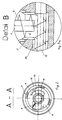
- FIG. 2 shows a cross section along line A - A of FIG. 1
- FIG. 3a shows an enlarged detail B from FIG. 1
- FIGS. 3b and 3c cross-sectional views of two variants of the device downstream of the device according to the invention Extruder according to line C - C in Fig.1, Fig.4, a second embodiment of the invention in longitudinal section, Figures 5 and 6 cross-sectional views along lines A - A and B - B of Fig.4, Fig.7, a third embodiment of the invention in longitudinal section, FIGS. 8 and 9 cross-sectional views along lines A - A and B - B of FIG. 4, FIG. 10 a fourth embodiment of the invention in longitudinal section and FIG. 11 a cross section along line A - A of FIG .10.
- FIG. 1 shows a first embodiment of the device for processing plastic material according to the invention.
- the device consists of a receptacle, generally designated 1, with a frustoconical, rotatable container part 2, which is rotatably mounted several times in a mounting frame 11 by bearings 14, a loading opening 3 for plastic material to be reprocessed, and a fixed container part 5, which is attached to the rotatable container part 2 borders and limits a discharge opening 6.
- a screw spiral 4 is arranged, whereby the container part 2, which acts as a hollow screw body, forms an external stuffing screw together with the screw spiral 4.
- This screw is driven by a drive 13 in the direction of arrow 10, whereby plastic material located in the container is conveyed in the direction of the discharge opening 6.
- the outer screw surrounds an inner screw, consisting of a cylindrical screw body 7 with a screw helix 8 mounted thereon, which is rotated in the direction of arrow 9 by a drive 12 and thus conveys plastic material in the direction of the discharge opening 6.
- the axes of rotation of the outer and inner screws coincide.
- the operation of the device is such that material introduced through the loading opening, which can consist of a wide variety of plastic waste, is conveyed through the two screws to the discharge opening, whereby through the steadily reducing clearance between the screws a considerable compression of the plastic material with accompanying agglomeration is achieved due to the heat generated.
- the frustoconical container design proves to be advantageous because it offers a very large volume in the loading area for the mostly very loosely packed plastic waste, which decreases steadily with increasing compaction.
- the pre-compressed plastic material finally arrives in the fixed container part 5 with the discharge opening 6.
- the inner stuffing screw 7,8 projects into this discharge opening.
- the fixed container part 5 is designed as a grooved bush, as can best be seen in the sectional view in FIG.
- the inner wall of the container part 5 has wound webs 16, between which grooves 15 are defined.
- the webs can have a conical shape.
- the grooves have a pushing effect on the material and prevent it from rotating in a circle.
- the connection between the device according to the invention and the extruder can be seen particularly well in FIGS. 2 and 3a, from which it can be seen that the extruder screw 19 runs at right angles to the stuffing screw 7,8 and the stuffing screw ends just above it.
- arrow 9 again designates the direction of rotation of the screw 7, 8.
- the extruder is provided with a conical groove bushing 20 on the feed.
- the extruder screw 19 is designed to be core-progressive, i.e. the core diameter gradually increases starting from the feed area.
- the extruder 17 can be an extruder with a single screw 19, as shown in FIG. 3b, which shows a cross section along line C - C in FIG. 1, the screw being conical, or alternatively, like in 3c also in cross section along line C - C in FIG. 1 - around a double extruder 17 with two screws 19.
- the direction of rotation of the two screws can either be opposite, as shown by the two thick arrows in the screw body, or in the same direction, in order to achieve better mixing or kneading with certain plastics. The latter case is symbolized by the thin arrows below the extruder.
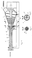
- FIGS. 4, 5 and 6 A second embodiment of the invention is shown in FIGS. 4, 5 and 6.
- the plastic preparation device according to the invention is coaxially connected to the downstream extruder 17, the inner stuffing screw of the device being formed in one piece with the extruder screw 19, namely as section 19 'of this extruder screw.
- This embodiment offers the advantage of a simpler construction and the elimination of a separate drive unit for the inner stuffing screw.
- the container is arranged essentially horizontally, which distinguishes the device according to the invention from the known prior art.
- the remaining parts of the device according to the invention are identical or similar to the first embodiment and are therefore provided with the same reference numerals. There is no need to describe these parts again; rather, reference is made to the detailed description above.
- the inner stuffing screw 19 is not cut all the way to its upstream end, but merges there into a cylindrical shaft.
- the outer screw 4 protrudes rearward beyond the inner screw and initially transports the plastic material supplied solely in the direction of the discharge opening.
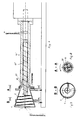
- FIGS. 7 to 9 A third embodiment of the invention is described in FIGS. 7 to 9, which is similar to the second embodiment, with the difference that the loading takes place at the center of the base of the container 2, which in turn is in one piece with the screw 19 "of the downstream extruder 17 ' trained inner stuffing screw 19 'of the device is only slightly exceeded by the outer stuffing screw and that the Extruder 17 'is provided with a melt outlet opening on the jacket side, which means that the extruder screw is provided in its end region with a counter-rotating screw helix which returns material that reaches beyond the outlet region.
- the extruder Since the compressed plastic material has a certain lubricating effect in the extruder, it is particularly important in this embodiment that the extruder is always filled with plastic material, which the device according to the invention, in contrast to the prior art, is capable of. At most, several plastic preparation devices according to the invention can also be combined with an extruder in order to ensure the sufficient material supply.
- the remaining parts of this embodiment are essentially identical in construction to the above embodiments, which is why a repeated description can be dispensed with.
- the outer stuffing screw was always coaxial with the inner stuffing screw.
- the axis of rotation of the rotatable container part 2 ', on the inner wall of which the outer screw spiral 4' is located closes with the axis of rotation of the inner stuffing screw 19 ', which is formed in one piece with the extruder screw 19 Angle, the lower generatrix of the container part 2 'running parallel to the axis of rotation of the screw 19'. In this way, an enlarged loading space is created above the screw 19 ', which allows higher material throughputs, particularly when loading with very loosely packed material. The loading takes place via the chute 21.
Landscapes
- Engineering & Computer Science (AREA)
- Mechanical Engineering (AREA)
- Environmental & Geological Engineering (AREA)
- Processing And Handling Of Plastics And Other Materials For Molding In General (AREA)
- Extrusion Moulding Of Plastics Or The Like (AREA)
Applications Claiming Priority (3)
| Application Number | Priority Date | Filing Date | Title |
|---|---|---|---|
| AT80696 | 1996-05-06 | ||
| AT806/96 | 1996-05-06 | ||
| AT0080696A AT407848B (de) | 1996-05-06 | 1996-05-06 | Vorrichtung und anlage zur aufbereitung von kunststoffgut |
Publications (3)
| Publication Number | Publication Date |
|---|---|
| EP0806280A2 true EP0806280A2 (fr) | 1997-11-12 |
| EP0806280A3 EP0806280A3 (fr) | 1998-05-13 |
| EP0806280B1 EP0806280B1 (fr) | 2001-07-11 |
Family
ID=3500147
Family Applications (1)
| Application Number | Title | Priority Date | Filing Date |
|---|---|---|---|
| EP19970890072 Expired - Lifetime EP0806280B1 (fr) | 1996-05-06 | 1997-04-18 | Dispositif et installation pour la préparation des matières plastiques |
Country Status (3)
| Country | Link |
|---|---|
| EP (1) | EP0806280B1 (fr) |
| AT (1) | AT407848B (fr) |
| DE (1) | DE59703992D1 (fr) |
Cited By (11)
| Publication number | Priority date | Publication date | Assignee | Title |
|---|---|---|---|---|
| WO1999011450A1 (fr) * | 1997-09-03 | 1999-03-11 | Baiyuan Lu | Appareil et procede d'alimentation pour extrudeuse |
| WO2000040391A1 (fr) * | 1999-01-07 | 2000-07-13 | Owens Corning | Dispositif d'alimentation et procede pour extrudeuse |
| CN102241158A (zh) * | 2011-05-23 | 2011-11-16 | 苏光宝 | 塑料粉末成型机自动加粉装置 |
| CN105108140A (zh) * | 2015-09-18 | 2015-12-02 | 苏州萨伯工业设计有限公司 | 一种稀土磁性材料生产自动加粉装置 |
| EP3156216A1 (fr) * | 2015-10-13 | 2017-04-19 | Dr. Collin GmbH | Tete d'impression mobile |
| CN104995019B (zh) * | 2013-02-01 | 2017-12-19 | 如福机械制造有限公司 | 用于给压块机供送团块材料的送料装置 |
| EP3332940A3 (fr) * | 2016-12-09 | 2018-09-26 | Raumedic AG | Installation d'extrusion de silicone, procédé d'extrusion de silicone ainsi qu'extrudat de silicone ainsi fabriqué |
| CN112357616A (zh) * | 2020-11-10 | 2021-02-12 | 广州红尚机械制造有限公司 | 一种出料装置 |
| CN114589828A (zh) * | 2022-02-22 | 2022-06-07 | 金华市华发新型建材有限公司 | 一种复合材料井盖生产系统 |
| EP3648946B1 (fr) * | 2017-07-04 | 2023-02-22 | AIM3D GmbH | Extrudeuse compactee et methode pour extruder de granules deformable thermomechanicquement |
| CN118634563A (zh) * | 2024-08-15 | 2024-09-13 | 沈阳石油化工设计院有限公司 | 一种精细化工生产挤压过滤机 |
Families Citing this family (1)
| Publication number | Priority date | Publication date | Assignee | Title |
|---|---|---|---|---|
| DE102019217113A1 (de) * | 2019-02-28 | 2020-09-03 | Aim3D Gmbh | Befülleinrichtung für die Zuführung von Verarbeitungsmaterial an eine Extruderschnecke und Verfahren zur Zuführung von Verarbeitungsmaterial an eine Extruderschnecke |
Family Cites Families (5)
| Publication number | Priority date | Publication date | Assignee | Title |
|---|---|---|---|---|
| GB882517A (en) * | 1956-11-15 | 1961-11-15 | Meyer Schlioma Frenkel | Apparatus for mixing |
| US3496601A (en) * | 1967-04-14 | 1970-02-24 | Midland Ross Corp | Feeder for auger-type extruder |
| US3563514A (en) * | 1968-03-11 | 1971-02-16 | Borg Warner | Plasticizer with full diameter rotor |
| SU725891A1 (ru) * | 1977-10-19 | 1980-04-05 | Предприятие П/Я В-8406 | Дегазационное устройство к экструдеру дл полимерных материалов |
| DD227648B1 (de) * | 1984-08-23 | 1989-10-04 | Karl Marx Stadt Maschf | Vorrichtung zur beschickung von extrusionsmaschinen mit voluminoesen, schlecht rieselfaehigen verarbeitungsguetern, insbesondere thermoplastabfaellen |
-
1996
- 1996-05-06 AT AT0080696A patent/AT407848B/de not_active IP Right Cessation
-
1997
- 1997-04-18 EP EP19970890072 patent/EP0806280B1/fr not_active Expired - Lifetime
- 1997-04-18 DE DE59703992T patent/DE59703992D1/de not_active Expired - Fee Related
Cited By (13)
| Publication number | Priority date | Publication date | Assignee | Title |
|---|---|---|---|---|
| US6299340B1 (en) | 1997-09-03 | 2001-10-09 | Baiyuan Lu | Feeding apparatus and method in spiral engagement of extruder |
| WO1999011450A1 (fr) * | 1997-09-03 | 1999-03-11 | Baiyuan Lu | Appareil et procede d'alimentation pour extrudeuse |
| WO2000040391A1 (fr) * | 1999-01-07 | 2000-07-13 | Owens Corning | Dispositif d'alimentation et procede pour extrudeuse |
| US6186655B1 (en) | 1999-01-07 | 2001-02-13 | Owens Corning Fiberglass Technology, Inc. | Auger fed extruder |
| CN102241158A (zh) * | 2011-05-23 | 2011-11-16 | 苏光宝 | 塑料粉末成型机自动加粉装置 |
| CN104995019B (zh) * | 2013-02-01 | 2017-12-19 | 如福机械制造有限公司 | 用于给压块机供送团块材料的送料装置 |
| CN105108140A (zh) * | 2015-09-18 | 2015-12-02 | 苏州萨伯工业设计有限公司 | 一种稀土磁性材料生产自动加粉装置 |
| EP3156216A1 (fr) * | 2015-10-13 | 2017-04-19 | Dr. Collin GmbH | Tete d'impression mobile |
| EP3332940A3 (fr) * | 2016-12-09 | 2018-09-26 | Raumedic AG | Installation d'extrusion de silicone, procédé d'extrusion de silicone ainsi qu'extrudat de silicone ainsi fabriqué |
| EP3648946B1 (fr) * | 2017-07-04 | 2023-02-22 | AIM3D GmbH | Extrudeuse compactee et methode pour extruder de granules deformable thermomechanicquement |
| CN112357616A (zh) * | 2020-11-10 | 2021-02-12 | 广州红尚机械制造有限公司 | 一种出料装置 |
| CN114589828A (zh) * | 2022-02-22 | 2022-06-07 | 金华市华发新型建材有限公司 | 一种复合材料井盖生产系统 |
| CN118634563A (zh) * | 2024-08-15 | 2024-09-13 | 沈阳石油化工设计院有限公司 | 一种精细化工生产挤压过滤机 |
Also Published As
| Publication number | Publication date |
|---|---|
| ATA80696A (de) | 2000-11-15 |
| DE59703992D1 (de) | 2001-08-16 |
| EP0806280A3 (fr) | 1998-05-13 |
| EP0806280B1 (fr) | 2001-07-11 |
| AT407848B (de) | 2001-06-25 |
Similar Documents
| Publication | Publication Date | Title |
|---|---|---|
| DE2214715C3 (de) | Schneckenstrangpresse für Kunststoffe | |
| EP3648946B1 (fr) | Extrudeuse compactee et methode pour extruder de granules deformable thermomechanicquement | |
| AT407972B (de) | Vorrichtung zum vorbehandeln und anschliessenden plastifizieren oder agglomerieren von kunststoffen | |
| AT413512B (de) | Vorrichtung zur aufbereitung von kunststoffmaterial zu recyclingzwecken | |
| DE4400330C2 (de) | Verfahren zum Herstellen eines geschäumten Produktes oder Schaumstoffmaterials aus nichtmodifizierter Stärke sowie Einrichtung zum Durchführen des Verfahrens | |
| AT413511B (de) | Vorrichtung zur aufbereitung von kunststoffmaterial zu recyclingzwecken | |
| WO2013052986A1 (fr) | Dispositif pour préparer une matière plastique | |
| DE10055097B4 (de) | Kontinuierlicher Mischer | |
| DE2330137A1 (de) | Mischextruder | |
| EP0806280B1 (fr) | Dispositif et installation pour la préparation des matières plastiques | |
| WO1995017293A1 (fr) | Dispositif de traitement de matieres thermoplastiques | |
| DE2924318C2 (de) | Zweistufige Schneckenstrangpreßvorrichtung für thermoplastische Formmassen, insbesondere für pulverförmige Kunststoffe | |
| DE1303676C2 (de) | Zentripetalstrangpresse zur verarbeitung thermoplastischer kunststoffe | |
| DE1271973B (de) | Kontinuierlich arbeitende Schneckenpresse fuer thermoplastische Kunststoffe von extrem geringem Schuettgewicht | |
| EP3883733B1 (fr) | Dispositif de traitement de matériau, en particulier un matériau plastique | |
| EP0071159A1 (fr) | Dispositif d'alimentation d'une extrudeuse à vis unique | |
| DE1729198B2 (de) | Schneckenstrangpresse fuer kunststoff | |
| AT522425B1 (de) | Schälschnecke | |
| DE2847494A1 (de) | Stopfwerk fuer kunststoffextruder | |
| DE3420643C2 (de) | Vorrichtung zum Wiederaufbereiten von thermoplastischen Abfällen | |
| DE2350746A1 (de) | Verfahren und vorrichtungen zur herstellung von granulaten aus pulverfoermigem, koernigem, teigfoermigem oder aehnlichem gut | |
| WO2002049827A1 (fr) | Systeme d'alimentation d'une installation d'extrusion destinee au recyclage de matieres plastiques | |
| EP4190530A1 (fr) | Dispositif d'alimentation en caoutchouc, en particulier en caoutchouc de silicone solide, par exemple une extrudeuse | |
| DE3004746A1 (de) | Extrusionsmaschine fuer keramikmaterial | |
| WO2024119211A1 (fr) | Procédé et dispositif de traitement de matériaux polymères |
Legal Events
| Date | Code | Title | Description |
|---|---|---|---|
| PUAI | Public reference made under article 153(3) epc to a published international application that has entered the european phase |
Free format text: ORIGINAL CODE: 0009012 |
|
| AK | Designated contracting states |
Kind code of ref document: A2 Designated state(s): DE FR GB IT |
|
| PUAL | Search report despatched |
Free format text: ORIGINAL CODE: 0009013 |
|
| AK | Designated contracting states |
Kind code of ref document: A3 Designated state(s): DE FR GB IT |
|
| 17P | Request for examination filed |
Effective date: 19980630 |
|
| GRAG | Despatch of communication of intention to grant |
Free format text: ORIGINAL CODE: EPIDOS AGRA |
|
| 17Q | First examination report despatched |
Effective date: 20000911 |
|
| GRAG | Despatch of communication of intention to grant |
Free format text: ORIGINAL CODE: EPIDOS AGRA |
|
| GRAH | Despatch of communication of intention to grant a patent |
Free format text: ORIGINAL CODE: EPIDOS IGRA |
|
| GRAH | Despatch of communication of intention to grant a patent |
Free format text: ORIGINAL CODE: EPIDOS IGRA |
|
| GRAA | (expected) grant |
Free format text: ORIGINAL CODE: 0009210 |
|
| AK | Designated contracting states |
Kind code of ref document: B1 Designated state(s): DE FR GB IT |
|
| REF | Corresponds to: |
Ref document number: 59703992 Country of ref document: DE Date of ref document: 20010816 |
|
| ITF | It: translation for a ep patent filed | ||
| GBT | Gb: translation of ep patent filed (gb section 77(6)(a)/1977) |
Effective date: 20010925 |
|
| ET | Fr: translation filed | ||
| REG | Reference to a national code |
Ref country code: GB Ref legal event code: IF02 |
|
| PGFP | Annual fee paid to national office [announced via postgrant information from national office to epo] |
Ref country code: GB Payment date: 20020308 Year of fee payment: 6 |
|
| PGFP | Annual fee paid to national office [announced via postgrant information from national office to epo] |
Ref country code: DE Payment date: 20020320 Year of fee payment: 6 |
|
| PGFP | Annual fee paid to national office [announced via postgrant information from national office to epo] |
Ref country code: FR Payment date: 20020425 Year of fee payment: 6 |
|
| PLBE | No opposition filed within time limit |
Free format text: ORIGINAL CODE: 0009261 |
|
| STAA | Information on the status of an ep patent application or granted ep patent |
Free format text: STATUS: NO OPPOSITION FILED WITHIN TIME LIMIT |
|
| 26N | No opposition filed | ||
| PG25 | Lapsed in a contracting state [announced via postgrant information from national office to epo] |
Ref country code: GB Free format text: LAPSE BECAUSE OF NON-PAYMENT OF DUE FEES Effective date: 20030418 |
|
| PG25 | Lapsed in a contracting state [announced via postgrant information from national office to epo] |
Ref country code: DE Free format text: LAPSE BECAUSE OF NON-PAYMENT OF DUE FEES Effective date: 20031101 |
|
| GBPC | Gb: european patent ceased through non-payment of renewal fee |
Effective date: 20030418 |
|
| PG25 | Lapsed in a contracting state [announced via postgrant information from national office to epo] |
Ref country code: FR Free format text: LAPSE BECAUSE OF NON-PAYMENT OF DUE FEES Effective date: 20031231 |
|
| REG | Reference to a national code |
Ref country code: FR Ref legal event code: ST |
|
| PG25 | Lapsed in a contracting state [announced via postgrant information from national office to epo] |
Ref country code: IT Free format text: LAPSE BECAUSE OF NON-PAYMENT OF DUE FEES Effective date: 20050418 |