EP0806271A2 - Hydraulisches Versorgungssystem für Holzspalter - Google Patents
Hydraulisches Versorgungssystem für Holzspalter Download PDFInfo
- Publication number
- EP0806271A2 EP0806271A2 EP97201135A EP97201135A EP0806271A2 EP 0806271 A2 EP0806271 A2 EP 0806271A2 EP 97201135 A EP97201135 A EP 97201135A EP 97201135 A EP97201135 A EP 97201135A EP 0806271 A2 EP0806271 A2 EP 0806271A2
- Authority
- EP
- European Patent Office
- Prior art keywords
- valving element
- cylinder
- piston
- oil
- piston unit
- Prior art date
- Legal status (The legal status is an assumption and is not a legal conclusion. Google has not performed a legal analysis and makes no representation as to the accuracy of the status listed.)
- Granted
Links
Images


Classifications
-
- B—PERFORMING OPERATIONS; TRANSPORTING
- B27—WORKING OR PRESERVING WOOD OR SIMILAR MATERIAL; NAILING OR STAPLING MACHINES IN GENERAL
- B27L—REMOVING BARK OR VESTIGES OF BRANCHES; SPLITTING WOOD; MANUFACTURE OF VENEER, WOODEN STICKS, WOOD SHAVINGS, WOOD FIBRES OR WOOD POWDER
- B27L7/00—Arrangements for splitting wood
-
- F—MECHANICAL ENGINEERING; LIGHTING; HEATING; WEAPONS; BLASTING
- F16—ENGINEERING ELEMENTS AND UNITS; GENERAL MEASURES FOR PRODUCING AND MAINTAINING EFFECTIVE FUNCTIONING OF MACHINES OR INSTALLATIONS; THERMAL INSULATION IN GENERAL
- F16N—LUBRICATING
- F16N29/00—Special means in lubricating arrangements or systems providing for the indication or detection of undesired conditions; Use of devices responsive to conditions in lubricating arrangements or systems
- F16N29/02—Special means in lubricating arrangements or systems providing for the indication or detection of undesired conditions; Use of devices responsive to conditions in lubricating arrangements or systems for influencing the supply of lubricant
Definitions
- This invention relates in a totally general manner to wood-splitting machines, and in particular to a hydraulic service system for said machines.
- Wood-splitting machines comprising a usually horizontal cradle intended to receive the wood pieces to be split, and provided with an anvil and an opposing wedge or blade between which the wood pieces are arranged.
- the wedge is fixed to the cradle structure, whereas the anvil is arranged to slide backwards and forwards under the control of a single or double acting hydraulic cylinder-piston unit.
- Said cylinder-piston unit is operated by a hydraulic power unit, with the delivery side of which there is associated at least one two-way slide valve in series with a usual overpressure or recirculation valve which is separate from the preceding, and can be regulated as required, to recirculate the oil on exceeding a predetermined pressure.
- known wood-splitting machines comprise either complicated and costly devices for operating a single valve, or at least two distribution valves positioned in series and keeping both the operator's hands occupied.
- the two said valves consist of two separate members, and are therefore positioned at different points of the hydraulic circuit, this involving substantial machining for forming the respective seats and connections, and the use of a relatively large number of components.
- the main object of the present invention is to provide means able to obviate the aforesaid problems within the context of a simple, rational and reliable construction.
- This maximum pressure, at which said valve unit automatically operates, can be adjusted according to requirements.
- means are preferably associated with the cylinder-piston unit to suddenly lower the oil pressure within the operating chamber of the cylinder-piston unit when the respective piston is close to its end of forward travel.
- FIGS. 1 and in particular Figure 1 show a wood-splitting machine 1, of usual general structure, comprising briefly a frame 2 lowerly provided with two wheels 3 and a support foot 4, and upperly comprising a cradle 5 for supporting the wood pieces to be split.
- a wedge 7 in front of which there is a movable anvil 8 controlled by an underlying single-acting hydraulic cylinder-piston unit 9, this latter being accommodated within the oil tank 88.
- the rod 99 of the cylinder-piston unit 9 extends beyond said wedge 7 where it carries fixed to it a crosspiece 10 from which there branch two opposing longitudinal connecting rods 11 connected to a collar 12 rigid with said anvil 8 (see Figures 1, 2).
- a power unit 13 consisting of an electric motor 130 and a hydraulic pump 131.
- the motor 130 is activated by an automatic switch-off switch 16 (see Figure 1), in particular consisting of a pushbutton with a return spring.
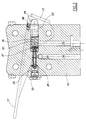
- the delivery conduit 14 of the pump 131 communicates with a through transverse hole 18 provided in the head 15 of the cylinder-piston unit 9 and from which there branches an intake and discharge conduit 19.
- Said hole 18 is positioned downstream of an orifice 20 which connects the conduit 14 to the hydraulic thrust chamber of the cylinder 100 of the cylinder-piston unit 9.
- Said hole 18 has three sections of different diameter, the central section, of smallest diameter, being that which communicates with the conduit 14 and constituting the housing for a valving element 21.
- Said piston 23 extends beyond the head 15 by means of an endpiece 24 of spherical cap shape, against which there rests the lever 17 by which the oil feed is controlled.
- the free end of the lever 17 is located on that side of the wood-splitting machine 1 (see Figure 1) on which the switch 16 is situated, the maximum travel of the lever 17 being limited by a threaded screw 66 screwed into the head 15 ( Figures 3 and 4).
- the valving element 21 is of mushroom shape comprising, in the stated order proceeding from left to right with reference to Figure 4, a hollow cylindrical stem 210 of different cross-sections which is accommodated, as an exact fit allowing free sliding, within the central smallest-diameter part of the hole 18; a valving portion 211 of frusto-conical shape the major base of which faces the piston 23 and has a diameter greater than that of said central part of the hole 18; and a flange 212.
- the spring 27 rests against said flange, said return conduit 19 opening into that part of the hole 18 which accommodates the latter spring.
- the first acts as a forward travel stop for the disc 26 and the second as the valve seat for the frusto-conical portion 211 of the valving element 21.
- the spring 25 merely ensures contact between the disc 26 and the stem 210 of the valving element 21, so maintaining this latter open by resting against the currently unloaded spring 27.
- the stem 210 of the valving element 21 has a first cylindrical portion situated towards said disc 26 and slidingly inserted as an exact fit into the central part of said hole 18, and a second cylindrical portion situated towards said spring 27 and accommodated within said central part of the hole 18 such as to leave a surrounding annular space.
- said narrow cross-section portion of the stem 210 lies substantially in correspondence with the end of the delivery conduit 14, with the frusto-conical portion 211 of the valving element spaced from its seal seat.
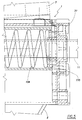
- the cylinder 100 of the cylinder-piston unit 9 is provided internally with two small diametrically opposite bulges or enlargements (see Figures 2 and 6), the bases of which have a diameter greater than the outer diameter of the seal ring 102 of the piston 103, and a length greater than the axial dimension of the ring 102.
- said bulges 101 define the forward stop position of the piston 103, as will be apparent hereinafter.
- the pumped oil follows the path defined by the delivery conduit 14, the passage gaps between the valving element 21 and the hole 18, and the return conduit 19.
- the spring 27 further shortens by an amount determined by the rotation of the lever 17, hence providing the closure force for the valving element 21, which compels the arriving oil to enter the hydraulic chamber of the cylinder-piston unit 9, with the result that the piston 103 slides against the thrust provided by the return spring 104.
- the shortening of said spring 27 provides a closure force for the valving element 21 (which at that moment acts as a feed valve), ie the force which determines the maximum pressure which the oil can attain, to cause the piston 103 to slide, said force being chosen at will by adjusting the screw 66.
- the valving element 21 remains closed and the piston 103 continues to slide until it reaches the bulges or enlargements 101.
- the power unit 13 operates at minimum load.
- the valving element 21 withdraws from its seat (hence acting as an overpressure valve) so that the arriving oil is recirculated through the conduit 19.
Landscapes
- Engineering & Computer Science (AREA)
- Life Sciences & Earth Sciences (AREA)
- General Engineering & Computer Science (AREA)
- Wood Science & Technology (AREA)
- Forests & Forestry (AREA)
- Mechanical Engineering (AREA)
- Fluid-Pressure Circuits (AREA)
- Jib Cranes (AREA)
- Electrical Discharge Machining, Electrochemical Machining, And Combined Machining (AREA)
- Valve-Gear Or Valve Arrangements (AREA)
- Chemical And Physical Treatments For Wood And The Like (AREA)
- Debarking, Splitting, And Disintegration Of Timber (AREA)
Applications Claiming Priority (2)
| Application Number | Priority Date | Filing Date | Title |
|---|---|---|---|
| IT96RE000029A IT1287641B1 (it) | 1996-05-08 | 1996-05-08 | Sistema idraulico di servizio per macchine spaccalegna |
| ITRE960029 | 1996-05-08 |
Publications (3)
| Publication Number | Publication Date |
|---|---|
| EP0806271A2 true EP0806271A2 (de) | 1997-11-12 |
| EP0806271A3 EP0806271A3 (de) | 1998-06-03 |
| EP0806271B1 EP0806271B1 (de) | 2000-02-16 |
Family
ID=11398871
Family Applications (1)
| Application Number | Title | Priority Date | Filing Date |
|---|---|---|---|
| EP97201135A Expired - Lifetime EP0806271B1 (de) | 1996-05-08 | 1997-04-17 | Hydraulisches Versorgungssystem für Holzspalter |
Country Status (5)
| Country | Link |
|---|---|
| EP (1) | EP0806271B1 (de) |
| AT (1) | ATE189788T1 (de) |
| DE (1) | DE69701300T2 (de) |
| DK (1) | DK0806271T3 (de) |
| IT (1) | IT1287641B1 (de) |
Cited By (9)
| Publication number | Priority date | Publication date | Assignee | Title |
|---|---|---|---|---|
| EP1213486A3 (de) * | 2000-12-05 | 2004-01-07 | Bell S.R.L. | Hydraulische Einrichtung mit einer Differentialschaltung, zum Beispiel eines durch einen einfach-wirkenden Zylinder betätigten Holzspaltgeräts |
| EP1350961A3 (de) * | 2002-04-05 | 2005-04-13 | Lawn & Garden Products (Laizhou) | Doppelt aktiviertes, hydraulisches Ventil mit Verschlussmechanismus |
| EP1676682A1 (de) * | 2005-01-04 | 2006-07-05 | TechTronic Industries, Co., Ltd | Holzspaltvorrichtung |
| EP1775084A1 (de) * | 2005-10-17 | 2007-04-18 | Bell S.R.L. | Holzspaltgerät |
| WO2007075905A1 (en) * | 2005-12-22 | 2007-07-05 | Mtd Products Inc. | Integral valve cylinder design for log splitter |
| WO2008028578A1 (de) * | 2006-09-05 | 2008-03-13 | Friedrich Reis | Vorrichtung zum spalten von abgelängten holzstämmen o.dgl. |
| WO2012167194A2 (en) | 2011-06-01 | 2012-12-06 | Blount, Inc. | Log splitter with two handed operation features |
| EP3144576A1 (de) * | 2015-08-21 | 2017-03-22 | Pisek - Vitli Krpan, d.o.o. | Mechanismus für automatische schmierung für holzspalter |
| EP3012076B1 (de) * | 2014-10-23 | 2018-04-25 | Scheppach Fabrikation von Holzbearbeitungsmaschinen GmbH | Holzspalter |
Families Citing this family (2)
| Publication number | Priority date | Publication date | Assignee | Title |
|---|---|---|---|---|
| DE102007025281B4 (de) * | 2007-05-30 | 2009-02-26 | Scheppach Fabrikation Von Holzbearbeitungsmaschinen Gmbh | Holzspalter mit Druckeinstellung |
| DE202008017052U1 (de) | 2008-12-23 | 2009-04-02 | Nairz, Christof | Holzspalter |
Family Cites Families (4)
| Publication number | Priority date | Publication date | Assignee | Title |
|---|---|---|---|---|
| US3077214A (en) * | 1959-08-27 | 1963-02-12 | Waco Aircraft Co | Log splitter |
| SE469375B (sv) * | 1991-01-04 | 1993-06-28 | Jerzy Janczak | Vedklyv |
| US5375638A (en) * | 1993-10-13 | 1994-12-27 | Clarke Power Products, Inc. | Log splitter |
| US5460211A (en) * | 1994-02-23 | 1995-10-24 | Minati; Frank E. | Component hydraulic log splitter |
-
1996
- 1996-05-08 IT IT96RE000029A patent/IT1287641B1/it active IP Right Grant
-
1997
- 1997-04-17 DE DE69701300T patent/DE69701300T2/de not_active Expired - Fee Related
- 1997-04-17 AT AT97201135T patent/ATE189788T1/de not_active IP Right Cessation
- 1997-04-17 EP EP97201135A patent/EP0806271B1/de not_active Expired - Lifetime
- 1997-04-17 DK DK97201135T patent/DK0806271T3/da active
Cited By (14)
| Publication number | Priority date | Publication date | Assignee | Title |
|---|---|---|---|---|
| EP1213486A3 (de) * | 2000-12-05 | 2004-01-07 | Bell S.R.L. | Hydraulische Einrichtung mit einer Differentialschaltung, zum Beispiel eines durch einen einfach-wirkenden Zylinder betätigten Holzspaltgeräts |
| EP1350961A3 (de) * | 2002-04-05 | 2005-04-13 | Lawn & Garden Products (Laizhou) | Doppelt aktiviertes, hydraulisches Ventil mit Verschlussmechanismus |
| CN100431812C (zh) * | 2005-01-04 | 2008-11-12 | 创科实业有限公司 | 劈木机 |
| EP1676682A1 (de) * | 2005-01-04 | 2006-07-05 | TechTronic Industries, Co., Ltd | Holzspaltvorrichtung |
| AU2005232264B2 (en) * | 2005-01-04 | 2011-07-14 | Techtronic Industries Co., Ltd | Log splitter |
| EP1775084A1 (de) * | 2005-10-17 | 2007-04-18 | Bell S.R.L. | Holzspaltgerät |
| WO2007075905A1 (en) * | 2005-12-22 | 2007-07-05 | Mtd Products Inc. | Integral valve cylinder design for log splitter |
| WO2008028578A1 (de) * | 2006-09-05 | 2008-03-13 | Friedrich Reis | Vorrichtung zum spalten von abgelängten holzstämmen o.dgl. |
| WO2012167194A2 (en) | 2011-06-01 | 2012-12-06 | Blount, Inc. | Log splitter with two handed operation features |
| CN103561922A (zh) * | 2011-06-01 | 2014-02-05 | 布楼恩特公司 | 具有两只手操作的特征的劈木机 |
| EP2714347A4 (de) * | 2011-06-01 | 2014-04-09 | Blount Inc | Holzspalter mit zweihandbetriebsfunktion |
| CN103561922B (zh) * | 2011-06-01 | 2016-08-17 | 布楼恩特公司 | 具有两只手操作的特征的劈木机 |
| EP3012076B1 (de) * | 2014-10-23 | 2018-04-25 | Scheppach Fabrikation von Holzbearbeitungsmaschinen GmbH | Holzspalter |
| EP3144576A1 (de) * | 2015-08-21 | 2017-03-22 | Pisek - Vitli Krpan, d.o.o. | Mechanismus für automatische schmierung für holzspalter |
Also Published As
| Publication number | Publication date |
|---|---|
| ITRE960029A1 (it) | 1997-11-08 |
| ITRE960029A0 (it) | 1996-05-08 |
| EP0806271A3 (de) | 1998-06-03 |
| DK0806271T3 (da) | 2000-07-24 |
| DE69701300T2 (de) | 2000-07-13 |
| EP0806271B1 (de) | 2000-02-16 |
| ATE189788T1 (de) | 2000-03-15 |
| DE69701300D1 (de) | 2000-03-23 |
| IT1287641B1 (it) | 1998-08-06 |
Similar Documents
| Publication | Publication Date | Title |
|---|---|---|
| EP0806271B1 (de) | Hydraulisches Versorgungssystem für Holzspalter | |
| US4947672A (en) | Hydraulic compression tool having an improved relief and release valve | |
| EP2024112B1 (de) | Verfahren zum betreiben eines hydraulischen verpressgerätes sowie hydraulisches verpressgerät | |
| EP1157786B1 (de) | Presswerkzeug für die Verpressung von Kupplungselementen | |
| KR930002474B1 (ko) | 유압 실린더용 밸브 | |
| US6276186B1 (en) | Hydraulic pressing device and method for operating the same | |
| KR930008543B1 (ko) | 수압 크림핑 공구 | |
| EP0841299A1 (de) | Hydrauliksystem für den Betrieb eines hydraulischen Wagenhebers | |
| US4497197A (en) | Pneumatic hydraulic hand-held power unit | |
| US20170298963A1 (en) | Integral Hydraulic System | |
| GB2255805A (en) | Hydraulic actuator | |
| EP0883754A1 (de) | Einfachwirkendes, pneumatisches kolben-zylinderaggregat | |
| US4498293A (en) | Hydraulic log splitter | |
| US20030070428A1 (en) | Electrohydraulic motor pump aggregate, attachable element and pressure limiting valve | |
| US3534679A (en) | Control means for pressure relief in hydraulic machines | |
| DE3639003A1 (de) | Hydraulisches fahrzeugbremssystem | |
| DE1947846B2 (de) | Druckmittelbremsanlage für Fahrzeuge | |
| CH400954A (de) | Mit Druckfluidum betriebener Kolbenmotor | |
| DE3723330A1 (de) | Hydraulisch betaetigtes handgeraet | |
| US2975803A (en) | Pressure release and relief valve | |
| DE2944011A1 (de) | Elektrische kraftverbindungsmaschine | |
| EP1213486B1 (de) | Holzspaltgerät mit einer Differentialschaltung eines einfach-wirkenden hydraulischen Zylinder | |
| EP3231765A1 (de) | Integriertes hydraulisches system | |
| DE2738177A1 (de) | Stroemungsmittelbetriebene hydraulische pumpe | |
| US4145164A (en) | Pump for hydraulic brake actuator |
Legal Events
| Date | Code | Title | Description |
|---|---|---|---|
| PUAI | Public reference made under article 153(3) epc to a published international application that has entered the european phase |
Free format text: ORIGINAL CODE: 0009012 |
|
| AK | Designated contracting states |
Kind code of ref document: A2 Designated state(s): AT BE CH DE DK ES FI FR GB GR IE IT LI LU MC NL PT SE |
|
| AX | Request for extension of the european patent |
Free format text: AL PAYMENT 970423;LT PAYMENT 970423;LV PAYMENT 970423;RO PAYMENT 970423;SI PAYMENT 970423 |
|
| PUAL | Search report despatched |
Free format text: ORIGINAL CODE: 0009013 |
|
| AK | Designated contracting states |
Kind code of ref document: A3 Designated state(s): AT BE CH DE DK ES FI FR GB GR IE IT LI LU MC NL PT SE |
|
| AX | Request for extension of the european patent |
Free format text: AL PAYMENT 970423;LT PAYMENT 970423;LV PAYMENT 970423;RO PAYMENT 970423;SI PAYMENT 970423 |
|
| 17P | Request for examination filed |
Effective date: 19980807 |
|
| 17Q | First examination report despatched |
Effective date: 19981118 |
|
| GRAG | Despatch of communication of intention to grant |
Free format text: ORIGINAL CODE: EPIDOS AGRA |
|
| GRAG | Despatch of communication of intention to grant |
Free format text: ORIGINAL CODE: EPIDOS AGRA |
|
| GRAH | Despatch of communication of intention to grant a patent |
Free format text: ORIGINAL CODE: EPIDOS IGRA |
|
| GRAH | Despatch of communication of intention to grant a patent |
Free format text: ORIGINAL CODE: EPIDOS IGRA |
|
| GRAA | (expected) grant |
Free format text: ORIGINAL CODE: 0009210 |
|
| AK | Designated contracting states |
Kind code of ref document: B1 Designated state(s): AT BE CH DE DK ES FI FR GB GR IE IT LI LU MC NL PT SE |
|
| AX | Request for extension of the european patent |
Free format text: AL PAYMENT 19970423;LT PAYMENT 19970423;LV PAYMENT 19970423;RO PAYMENT 19970423;SI PAYMENT 19970423 |
|
| LTIE | Lt: invalidation of european patent or patent extension | ||
| PG25 | Lapsed in a contracting state [announced via postgrant information from national office to epo] |
Ref country code: GR Free format text: LAPSE BECAUSE OF NON-PAYMENT OF DUE FEES Effective date: 20000216 Ref country code: ES Free format text: THE PATENT HAS BEEN ANNULLED BY A DECISION OF A NATIONAL AUTHORITY Effective date: 20000216 |
|
| REF | Corresponds to: |
Ref document number: 189788 Country of ref document: AT Date of ref document: 20000315 Kind code of ref document: T |
|
| REG | Reference to a national code |
Ref country code: CH Ref legal event code: NV Representative=s name: ISLER & PEDRAZZINI AG Ref country code: CH Ref legal event code: EP |
|
| REF | Corresponds to: |
Ref document number: 69701300 Country of ref document: DE Date of ref document: 20000323 |
|
| ET | Fr: translation filed | ||
| ITF | It: translation for a ep patent filed | ||
| PG25 | Lapsed in a contracting state [announced via postgrant information from national office to epo] |
Ref country code: LU Free format text: LAPSE BECAUSE OF NON-PAYMENT OF DUE FEES Effective date: 20000417 Ref country code: IE Free format text: LAPSE BECAUSE OF NON-PAYMENT OF DUE FEES Effective date: 20000417 |
|
| REG | Reference to a national code |
Ref country code: IE Ref legal event code: FG4D |
|
| PG25 | Lapsed in a contracting state [announced via postgrant information from national office to epo] |
Ref country code: PT Free format text: LAPSE BECAUSE OF FAILURE TO SUBMIT A TRANSLATION OF THE DESCRIPTION OR TO PAY THE FEE WITHIN THE PRESCRIBED TIME-LIMIT Effective date: 20000516 |
|
| REG | Reference to a national code |
Ref country code: DK Ref legal event code: T3 |
|
| PG25 | Lapsed in a contracting state [announced via postgrant information from national office to epo] |
Ref country code: MC Free format text: LAPSE BECAUSE OF NON-PAYMENT OF DUE FEES Effective date: 20001031 |
|
| PLBE | No opposition filed within time limit |
Free format text: ORIGINAL CODE: 0009261 |
|
| STAA | Information on the status of an ep patent application or granted ep patent |
Free format text: STATUS: NO OPPOSITION FILED WITHIN TIME LIMIT |
|
| 26N | No opposition filed | ||
| REG | Reference to a national code |
Ref country code: IE Ref legal event code: MM4A |
|
| REG | Reference to a national code |
Ref country code: GB Ref legal event code: IF02 |
|
| PGFP | Annual fee paid to national office [announced via postgrant information from national office to epo] |
Ref country code: FR Payment date: 20040408 Year of fee payment: 8 |
|
| PGFP | Annual fee paid to national office [announced via postgrant information from national office to epo] |
Ref country code: GB Payment date: 20040413 Year of fee payment: 8 Ref country code: AT Payment date: 20040413 Year of fee payment: 8 |
|
| PGFP | Annual fee paid to national office [announced via postgrant information from national office to epo] |
Ref country code: CH Payment date: 20040414 Year of fee payment: 8 |
|
| PGFP | Annual fee paid to national office [announced via postgrant information from national office to epo] |
Ref country code: SE Payment date: 20040415 Year of fee payment: 8 Ref country code: FI Payment date: 20040415 Year of fee payment: 8 |
|
| PGFP | Annual fee paid to national office [announced via postgrant information from national office to epo] |
Ref country code: DK Payment date: 20040426 Year of fee payment: 8 |
|
| PGFP | Annual fee paid to national office [announced via postgrant information from national office to epo] |
Ref country code: DE Payment date: 20040427 Year of fee payment: 8 |
|
| PGFP | Annual fee paid to national office [announced via postgrant information from national office to epo] |
Ref country code: NL Payment date: 20040429 Year of fee payment: 8 |
|
| PGFP | Annual fee paid to national office [announced via postgrant information from national office to epo] |
Ref country code: BE Payment date: 20040511 Year of fee payment: 8 |
|
| PG25 | Lapsed in a contracting state [announced via postgrant information from national office to epo] |
Ref country code: IT Free format text: LAPSE BECAUSE OF NON-PAYMENT OF DUE FEES;WARNING: LAPSES OF ITALIAN PATENTS WITH EFFECTIVE DATE BEFORE 2007 MAY HAVE OCCURRED AT ANY TIME BEFORE 2007. THE CORRECT EFFECTIVE DATE MAY BE DIFFERENT FROM THE ONE RECORDED. Effective date: 20050417 Ref country code: GB Free format text: LAPSE BECAUSE OF NON-PAYMENT OF DUE FEES Effective date: 20050417 Ref country code: FI Free format text: LAPSE BECAUSE OF NON-PAYMENT OF DUE FEES Effective date: 20050417 Ref country code: AT Free format text: LAPSE BECAUSE OF NON-PAYMENT OF DUE FEES Effective date: 20050417 |
|
| PG25 | Lapsed in a contracting state [announced via postgrant information from national office to epo] |
Ref country code: SE Free format text: LAPSE BECAUSE OF NON-PAYMENT OF DUE FEES Effective date: 20050418 |
|
| PG25 | Lapsed in a contracting state [announced via postgrant information from national office to epo] |
Ref country code: LI Free format text: LAPSE BECAUSE OF NON-PAYMENT OF DUE FEES Effective date: 20050430 Ref country code: CH Free format text: LAPSE BECAUSE OF NON-PAYMENT OF DUE FEES Effective date: 20050430 Ref country code: BE Free format text: LAPSE BECAUSE OF NON-PAYMENT OF DUE FEES Effective date: 20050430 |
|
| PG25 | Lapsed in a contracting state [announced via postgrant information from national office to epo] |
Ref country code: DK Free format text: LAPSE BECAUSE OF NON-PAYMENT OF DUE FEES Effective date: 20050502 |
|
| BERE | Be: lapsed |
Owner name: *BELL S.R.L. Effective date: 20050430 |
|
| PG25 | Lapsed in a contracting state [announced via postgrant information from national office to epo] |
Ref country code: NL Free format text: LAPSE BECAUSE OF NON-PAYMENT OF DUE FEES Effective date: 20051101 Ref country code: DE Free format text: LAPSE BECAUSE OF NON-PAYMENT OF DUE FEES Effective date: 20051101 |
|
| REG | Reference to a national code |
Ref country code: DK Ref legal event code: EBP |
|
| EUG | Se: european patent has lapsed | ||
| REG | Reference to a national code |
Ref country code: CH Ref legal event code: PL |
|
| GBPC | Gb: european patent ceased through non-payment of renewal fee |
Effective date: 20050417 |
|
| PG25 | Lapsed in a contracting state [announced via postgrant information from national office to epo] |
Ref country code: FR Free format text: LAPSE BECAUSE OF NON-PAYMENT OF DUE FEES Effective date: 20051230 |
|
| NLV4 | Nl: lapsed or anulled due to non-payment of the annual fee |
Effective date: 20051101 |
|
| REG | Reference to a national code |
Ref country code: FR Ref legal event code: ST Effective date: 20051230 |
|
| BERE | Be: lapsed |
Owner name: *BELL S.R.L. Effective date: 20050430 |