EP0806262A1 - Verfahren und Vorrichtung zum Wellenlöten oder Wellenverzinnen - Google Patents
Verfahren und Vorrichtung zum Wellenlöten oder Wellenverzinnen Download PDFInfo
- Publication number
- EP0806262A1 EP0806262A1 EP97400803A EP97400803A EP0806262A1 EP 0806262 A1 EP0806262 A1 EP 0806262A1 EP 97400803 A EP97400803 A EP 97400803A EP 97400803 A EP97400803 A EP 97400803A EP 0806262 A1 EP0806262 A1 EP 0806262A1
- Authority
- EP
- European Patent Office
- Prior art keywords
- wave
- injector
- gas
- wall
- orifices
- Prior art date
- Legal status (The legal status is an assumption and is not a legal conclusion. Google has not performed a legal analysis and makes no representation as to the accuracy of the status listed.)
- Granted
Links
Images


Classifications
-
- B—PERFORMING OPERATIONS; TRANSPORTING
- B23—MACHINE TOOLS; METAL-WORKING NOT OTHERWISE PROVIDED FOR
- B23K—SOLDERING OR UNSOLDERING; WELDING; CLADDING OR PLATING BY SOLDERING OR WELDING; CUTTING BY APPLYING HEAT LOCALLY, e.g. FLAME CUTTING; WORKING BY LASER BEAM
- B23K1/00—Soldering, e.g. brazing, or unsoldering
- B23K1/08—Soldering by means of dipping in molten solder
- B23K1/085—Wave soldering
-
- B—PERFORMING OPERATIONS; TRANSPORTING
- B23—MACHINE TOOLS; METAL-WORKING NOT OTHERWISE PROVIDED FOR
- B23K—SOLDERING OR UNSOLDERING; WELDING; CLADDING OR PLATING BY SOLDERING OR WELDING; CUTTING BY APPLYING HEAT LOCALLY, e.g. FLAME CUTTING; WORKING BY LASER BEAM
- B23K2101/00—Articles made by soldering, welding or cutting
- B23K2101/36—Electric or electronic devices
- B23K2101/42—Printed circuits
Definitions
- the invention relates to the soldering or tinning operations carried out using machines comprising a liquid solder bath, whether this bath is qualified as “dead bath” or whether it is set in motion as in so-called “soldering machines”. to the wave ".
- These machines are used in particular for soldering electronic components on a support such as an electronic circuit, or also for tinning of terminations of electronic components.
- the design of wave soldering machines is such that the soldering circuits (or the parts to be tin plated) are brought into contact with one or more waves of liquid solder obtained by pumping a solder bath contained in a tank through a nozzle.
- the parts Beforehand, the parts have generally been fluxed in an area upstream of the machine, so as mainly to deoxidize the metal surfaces to facilitate their subsequent wetting by welding, the fluxing operation being followed by a preheating operation which is used both to activate the flows previously deposited on the circuit and to preheat the circuits and components before they arrive in the hot soldering zone.
- Wave soldering machines most commonly comprise two waves, a first wave called “turbulent” and a second wave called “laminar", this second type of wave offering a relatively large flat upper surface.
- the machines are then most often provided with a system which can be described as a weir, the height allows to adjust the flow rate of the weld downstream.
- This weir system can simply consist of a metal plate, or a chute guiding the fallout of the weld to the surrounding bath.
- Wave soldering (or tinning) machines are traditionally open to the atmosphere of ambient air.
- problems encountered by users of such machines mention may be made of the formation of oxide layers (called slag) on the surface of the solder bath due to its exposure to air, resulting in a significant loss of solder and the need to regularly clean the bath.
- slag oxide layers
- a medium-sized machine can give rise to the formation of more than one kilo of slag per hour of operation.
- a first category of solution consists in the establishment of a confined protective atmosphere, at least above the weld pool, but also sometimes in the rest of the machine.
- a second category of solutions uses the installation of unconfined protective atmospheres, via injectors located near the waves of welding, without closing the space above the waves.
- the third category of solutions to the problem of slag formation involves the use, on the surface of the laminar wave, of a film of oil with high covering power.
- Oil protection systems have the classic drawbacks of using oil (especially in the presence of a temperature source), which are in particular the presence of oil deposits on the card requiring the realization of often difficult and imperfect cleaning, the need to carry out frequent machine maintenance periods due to the accumulation of oil in the solder bath, or the fumes of oil vapors which undoubtedly represent a nuisance for the environment, whether material or human.
- One of the objectives of the present invention is therefore to propose a wave soldering or tinning machine enabling localized inerting (therefore without the need of using a confinement system) of the flat surface of a laminar wave (laminar wave which has, as we have seen, quite specific operating problems due to its extremely low flow), the design of the machine having to make it possible to obtain in a very simple and economical manner a very good compromise between the residual oxygen content damage to the laminar wave surface and the flow of gas used in this wave, this flow rate if necessary, to meet the economic specifications of certain user sites, be able to be below 10m 3 / h, and preferably less than or equal to 5m 3 / h.
- the machine includes a weir system whose height adjustment with respect to the wave makes it possible to adjust the overflow rate of the wave downstream, the weir system is having the form of a chute, plunging into the welding tank, or provided with a structure of a plunging skirt in the welding tank, the wall comprising a second group of orifices, positioned on the wall so as to allow '' inject a second jet of gas inside the chute or skirt.
- the injector and the chute then have a common wall, this one is provided with injection orifices.
- the gas of the second jet passes directly from the interior of the injector to the interior of the skirt.
- This configuration has significant advantages in terms of ease of manufacture of the assembly, and therefore of production cost.
- the injection of a second gas jet inside the skirt may for example be obtained by placing the second group of orifices facing an opening defined in a wall of the skirt, or even at the interface between the skirt and the chute, or even in the lower part of the chute, depending on the initial geometry adopted.
- the machine comprises a weir system which is in the form of a plate, plunging into the welding tank, the wall of the injector then comprising a second group of orifices, positioned on the wall so as to allow a second jet of gas to be injected into the space between the plate and the injector.
- a weir system which is in the form of a plate, plunging into the welding tank, the wall of the injector then comprising a second group of orifices, positioned on the wall so as to allow a second jet of gas to be injected into the space between the plate and the injector.
- gas delivery "orifices" must be understood as any type of configuration of holes allowing gas to escape from the injector, whether for example conventional circular orifices or slots.
- the first group of orifices will advantageously be positioned on the wall of the injector so as to direct the first gas jet tangentially to the flat surface of the laminar wave. Such an arrangement will favor obtaining a COANDA effect of the gas jet on the surface of the wave, thus making inerting more effective.
- Such an arrangement for injecting the second gas jet inside the skirt has proved to be surprisingly effective in avoiding parasitic phenomena of air entrainment by the first gas jet.
- the orifices of at least one of the groups of orifices are advantageously sized so as to allow obtaining a gas velocity at the outlet of the orifices considered lying in the range between 0.5 and 30 m / s. However, it will preferably operate in the speed range from 0.5 to 10 m / s, and more preferably in the reduced range from 0.5 to 5 m / s.
- the injection means extend over the entire width of the laminar wave, thus adapting more effectively to all the dimensions of the parts which it is possible to process in the machine in question.
- the first group of orifices consists of at least one row of slots delimited in the wall of the injector facing the wave.
- the injection means may include means for delivering the gas inside the injector, which may for example consist of a porous tube located inside the injector itself, and capable of being supplied with the outside in the gas under consideration, or even a simple "clarinet", a term which traditionally covers the notion of tube pierced with holes.
- the injector is provided with an upper face or wall.
- the work carried out by the Applicant have demonstrated that it is then advantageous to use a deflecting part secured to this upper wall.
- Such a deflecting part preferably extends over the entire length of the injector.
- the dimensions of the deflecting part are such that the deflecting part extends in width by so as to at least cover the weir system (for example the chute).
- the position of the injector will preferably be adjustable horizontally and / or vertically.
- the brazing or tinning machine makes it possible to use, at the level of the injector, any type of gas, whether it is neutral (such as nitrogen whatever whatever its mode of production and its purity) or even more active such as, for example, neutral gas / reducing gas mixtures.
- the invention also relates to a method of brazing or tinning of a part wave, during which a part to be brazed or tin plated is brought into contact with at least one wave of liquid solder of so-called laminar form, according to which a shielding gas on at least a portion of the wave, and characterized in that the shielding gas is directed onto the wave by means of an injector located in an adjacent position downstream of the wave, and provided with a wall located facing the wave, comprising at least a first group of orifices positioned on the wall so as to allow obtaining a first jet of gas directed towards the flat surface of the laminar wave, the speed of the gas leaving d orifices being between 0.5 and 30 m / s, but preferably between 0.5 and 10 m / s, and more preferably between 0.5 and 5 m / s.
- the overflow rate of the welding wave is adjusted downstream by the use of a weir system of height adjustable relative to the wave, the weir system in the form of a chute, plunging into the welding tank or provided with a skirt dipping into the welding tank, and the wall of the injector then comprises a second group of orifices positioned on the wall so as to allow the injection of a second gas jet inside the chute or the plunging skirt.
- the overflow rate of the welding wave is adjusted downstream by the use of a weir system in the form of a plate, plunging into the welding tank.
- the wall of the injector comprising a second group of orifices, positioned on the wall so as to allow a second jet of gas to be injected into the space between the plate and the injector.
- the invention also relates to a laminar wave inerting device of a wave soldering or tinning machine, comprising a gas injector located in an adjacent position downstream of the laminar wave, and provided with a wall located in look of the laminar wave, the wall comprising at least a first group of orifices positioned on the wall so as to allow obtaining a first jet of gas directed towards the flat surface of the laminar wave.
- the injector is provided with an upper wall and the device comprises a deflecting part secured to the upper wall of the injector.
- the brazing or tinning machine comprises a weir system, the adjustment of the height of which with respect to the wave makes it possible to adjust the overflow rate of the welding wave downstream of the machine, the weir system being in the form of a plunging plate in the weld tank or a guide trough plunging in the weld tank or else that is provided with a plunging skirt in the tank the injector wall of the device is then provided with a second group orifices, positioned on the wall so as to allow a second gas jet to be obtained directed inside the chute or else inside the space between the plate and the injector
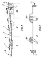
- the wave soldering machine shown diagrammatically in FIG. 1 comprises three zones: a zone I for fluxing the parts 1 by a fluxing system 3 (for example of the foam type), a zone II for preheating the fluxed parts, by means 4 for example made up of infrared lamps, and a zone III of actual soldering where the parts 1 meet, in the embodiment shown, a single wave of solder 8 obtained by pumping (7) the solder bath 9 through '' a welding nozzle 6.
- the cards 1 are conveyed along the different zones of the machine using a conveyor system 2, for example consisting of frames moving on two lateral bands located on each side of the machine, or else conveyor chains " with fingers ”.
- a conveyor system 2 for example consisting of frames moving on two lateral bands located on each side of the machine, or else conveyor chains " with fingers ”.
- Figure 2 provides a schematic sectional and partial view of a case where the weld pool 9 gives rise to the formation of a double wave structure, a first so-called turbulent wave 8a of relatively abrupt structure (obtained thanks to the structure nozzle 6a), and a second wave 8b of laminar structure, providing a planar upper surface of relatively large dimension, obtained by the nozzle structure 6b.
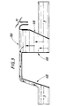
- FIGS. 3 and 4 illustrate the flow of the welding of the laminar wave 8b respectively in a waiting position for parts and in a situation of soldering a card 1.
- FIG. 3 therefore illustrates a waiting situation for a part with the solder flowing upstream of the machine.
- the embodiment shown here includes the use of a weir system 10, in the form of a guide trough, located just downstream of the nozzle, and making it possible, by adjusting its height, to adjust the discharge rate of the weld downstream (here in this case a zero or almost zero flow).
- the arrival of the part 1 on the laminar wave causes a partial reversal of the flow of the liquid weld downstream of the machine (ie towards the front), the discharge rate forwards being adjustable by the adjusting the height of the trough system 10.
- the use of such a trough (instead of a simple plate attached to the nozzle 6b also makes it possible to better guide and reduce the weld spill towards the bath 9.
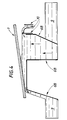
- FIG. 5 schematically and partially illustrates an embodiment of a wave soldering or tinning machine according to the invention, the representation being partial since it is centered on the laminar wave / injector / chute / skirt arrangement.
- the wave is shown here in the waiting position for parts with flow upstream.
- chute and the skirt of which it is integral by two different lines this to facilitate understanding of the figure.
- the chute and skirt may not, according to the invention, be two separate parts made integral, it is also possible from the outset to use a plunging chute.
- the groups of orifices 15 and 16 are respectively positioned so as to be able to direct a first jet of gas towards the flat surface of the laminar wave 8b, and a second jet of gas inside the plunging skirt 11.
- a first jet of gas towards the flat surface of the laminar wave 8b
- a second jet of gas inside the plunging skirt 11 is particularly effective in avoiding possible air entrainment effects on the flat surface of the laminar wave.
- FIG. 6 The structure shown diagrammatically in FIG. 6 is similar to that shown in the context of FIG. 5, except for the presence of a deflecting part 13 secured to an upper wall 19 of the injector 12.
- the presence of the deflecting part 13 has proved to be very effective in achieving, if necessary, very low residual oxygen contents at the level of the planar surface. the laminar wave.
- FIG. 6 illustrates an advantageous embodiment of the invention where the width of the deflecting part (if necessary in combination with the position of the injector relative to the wave) makes it possible to extend to at least cover the chute system.
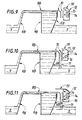
- FIG. 7 which is a detailed partial view of the injector 12 and of the deflector piece 13 in FIG. 6, makes it possible to better understand the respective position of the deflector piece 13 and of the injector 12, in particular the arrangement of this deflecting part 13 on the upper wall 19 of the injector. This figure also makes it possible to better visualize the configuration of orifices of the two groups of orifices 15 and 16.
- the groups of orifices 15 and 16 respectively consist of three and a row of slots 18, both located on the wall 17 of the injector 12, and extending over the entire length of this injector.
- FIG. 8 illustrates a particular embodiment of the invention where the chute and the injector have a common wall. It is in fact noted that the wall 17 of the injector here forms one of the walls of the chute, this wall extending by one of the sides of the skirt 11.
- the second jet of gas from the second group 16 of orifices passes directly from the interior of the injector 12 to the interior of the skirt 11.
- a first type of evaluation was carried out using these three configurations, on a double wave wave soldering machine: a measurement of the residual oxygen content on the surface of the laminar wave, in the presence and in l absence of soldering cards. An observation of the formation or not of slag on the flat surface of the laminar wave was also systematically carried out.
- the nitrogen flow rate implemented by the injector is 80 l / min
- the nitrogen used was nitrogen of cryogenic origin, the residual oxygen concentration of which is less than or equal to 10 ppm.
- a second type of evaluation was carried out in the case of the structure of FIG. 11: the evaluation of the presence or not of two types of soldering faults on electronic cards soldered in the machine: the lack of soldering and the short circuits (solder bridges).
- the evaluation was carried out both under nitrogen (flow rate mentioned above) and under air.
- the machine and the wave soldering method according to the invention allow, dramatically, to reach, for an extremely reasonable nitrogen consumption, contents very low residual oxygen at the surface of the laminar wave, consistent with a marked improvement in brazing performance obtained, and excellent results in the field of slag.
Landscapes
- Engineering & Computer Science (AREA)
- Mechanical Engineering (AREA)
- Molten Solder (AREA)
- Electric Connection Of Electric Components To Printed Circuits (AREA)
- Arc Welding In General (AREA)
- Auxiliary Devices For And Details Of Packaging Control (AREA)
- Coating With Molten Metal (AREA)
Applications Claiming Priority (2)
| Application Number | Priority Date | Filing Date | Title |
|---|---|---|---|
| FR9605724 | 1996-05-07 | ||
| FR9605724A FR2748410B1 (fr) | 1996-05-07 | 1996-05-07 | Procede et machine de brasage ou etamage a la vague |
Publications (2)
| Publication Number | Publication Date |
|---|---|
| EP0806262A1 true EP0806262A1 (de) | 1997-11-12 |
| EP0806262B1 EP0806262B1 (de) | 2002-02-13 |
Family
ID=9491930
Family Applications (1)
| Application Number | Title | Priority Date | Filing Date |
|---|---|---|---|
| EP97400803A Expired - Lifetime EP0806262B1 (de) | 1996-05-07 | 1997-04-08 | Verfahren und Vorrichtung zum Wellenlöten oder Wellenverzinnen |
Country Status (10)
| Country | Link |
|---|---|
| US (4) | US5725143A (de) |
| EP (1) | EP0806262B1 (de) |
| JP (1) | JPH10113765A (de) |
| CN (1) | CN1109484C (de) |
| DE (1) | DE69710383T2 (de) |
| DK (1) | DK0806262T3 (de) |
| ES (1) | ES2171851T3 (de) |
| FR (1) | FR2748410B1 (de) |
| PT (1) | PT806262E (de) |
| TW (1) | TW331535B (de) |
Cited By (1)
| Publication number | Priority date | Publication date | Assignee | Title |
|---|---|---|---|---|
| FR2835917A1 (fr) * | 2002-02-12 | 2003-08-15 | Air Liquide | Installation de mesure de mouillabilite |
Families Citing this family (25)
| Publication number | Priority date | Publication date | Assignee | Title |
|---|---|---|---|---|
| FR2748410B1 (fr) * | 1996-05-07 | 1998-06-05 | Air Liquide | Procede et machine de brasage ou etamage a la vague |
| DE69712719T2 (de) * | 1996-06-11 | 2002-11-21 | Kabushiki Kaisha Tamura Seisakusho, Tokio/Tokyo | Lötvorrichtung |
| JPH10125618A (ja) * | 1996-10-23 | 1998-05-15 | Fujitsu Ltd | 半導体装置の製造方法 |
| US6013535A (en) | 1997-08-05 | 2000-01-11 | Micron Technology, Inc. | Method for applying adhesives to a lead frame |
| US6336973B1 (en) | 1997-08-05 | 2002-01-08 | Micron Technology, Inc. | Apparatus and method for modifying the configuration of an exposed surface of a viscous fluid |
| US6040205A (en) * | 1997-08-05 | 2000-03-21 | Micron Technology, Inc. | Apparatus and method for controlling the depth of immersion of a semiconductor element in an exposed surface of a viscous fluid |
| DE19749185A1 (de) * | 1997-11-07 | 1999-05-12 | Messer Griesheim Gmbh | Mit einer Gasversorgung verbindbare Gasverteilung |
| US6257480B1 (en) * | 1998-07-07 | 2001-07-10 | Denso Corporation | Jet soldering method and apparatus |
| US6234380B1 (en) * | 1998-10-29 | 2001-05-22 | L'air Liquide, Societe Anonyme Pour L'etude Et L'exploitation Des Procedes Georges Claude | Apparatus and method for inerting a wave soldering installation |
| TWI247562B (en) * | 1999-06-02 | 2006-01-11 | Speedline Technologies Inc | Closed loop solder wave height control system |
| JP2002172459A (ja) * | 2000-09-26 | 2002-06-18 | Sony Corp | はんだ付け装置 |
| MY124946A (en) * | 2000-10-23 | 2006-07-31 | Senju Metal Industry Co | Automatic wave soldering apparatus and method |
| US7918383B2 (en) * | 2004-09-01 | 2011-04-05 | Micron Technology, Inc. | Methods for placing substrates in contact with molten solder |
| DE102004061572A1 (de) * | 2004-12-21 | 2006-07-06 | Linde Ag | Verfahren zum Wellenlöten |
| DE102007033865A1 (de) * | 2007-07-20 | 2009-01-22 | Seho Systemtechnik Gmbh | Schwalllötanlage zum Löten von elektrischen Bauteilen |
| FR2926233B1 (fr) * | 2008-01-10 | 2010-08-13 | Air Liquide | Dispositif d'alimentation en gaz d'une machine de brasage ou etamage a la vague. |
| CN101608292B (zh) * | 2009-07-13 | 2011-03-16 | 薛树津 | 电缆编织外导体的镀锡方法及其专用镀锡设备 |
| US20110139855A1 (en) * | 2009-12-16 | 2011-06-16 | Ristolainen Tero | Residual oxygen measurement and control in wave soldering process |
| KR20110129151A (ko) * | 2010-05-25 | 2011-12-01 | 삼성전자주식회사 | 부력 인가 수단을 가진 웨이브 솔더링 장치와 솔더링 방법 및 플립 칩용 솔더 범프 형성 방법 |
| CN102485395A (zh) * | 2010-12-02 | 2012-06-06 | 西安大昱光电科技有限公司 | 一种低容量波峰发生器 |
| US8579182B2 (en) * | 2011-06-17 | 2013-11-12 | Air Products And Chemicals, Inc. | Method for providing an inerting gas during soldering |
| ITMI20111131A1 (it) * | 2011-06-21 | 2012-12-22 | Danieli Off Mecc | Dispositivo di generazione di getto di gas per processi di rivestimento di nastri metallici |
| US20140027495A1 (en) * | 2012-04-18 | 2014-01-30 | Air Products And Chemicals Inc. | Apparatus And Method For Providing An Inerting Gas During Soldering |
| CN103212761B (zh) * | 2012-06-26 | 2015-05-06 | 深圳市堃琦鑫华股份有限公司 | 一种焊接方法 |
| CN104801809B (zh) * | 2014-01-29 | 2018-09-14 | 气体产品与化学公司 | 用于在焊接期间提供惰性气体的设备和方法 |
Citations (3)
| Publication number | Priority date | Publication date | Assignee | Title |
|---|---|---|---|---|
| EP0621101A1 (de) * | 1993-04-23 | 1994-10-26 | Kawakatsu, Ichiro | Verfahren und Vorrichtung zum Löten eines Werkstückes in nichtoxydierenden Atmosphäre |
| US5409159A (en) * | 1994-02-28 | 1995-04-25 | L'air Liquide, Societe Anonyme Pour L'etude Et L'exploitation Des Procedes Georges Claude | Apparatus and methods for inerting solder during wave soldering operations |
| EP0713742A1 (de) * | 1994-11-23 | 1996-05-29 | Electrovague | Einblasvorrichtung für Inertglas, insbesondere Stickstoff, für eine Wellenlötmaschine und mit solcher Vorrichtung ausgerüstete Wellenlötmaschine |
Family Cites Families (14)
| Publication number | Priority date | Publication date | Assignee | Title |
|---|---|---|---|---|
| US4610391A (en) * | 1984-12-18 | 1986-09-09 | Union Carbide Corporation | Process for wave soldering |
| US4679720A (en) * | 1986-10-23 | 1987-07-14 | Hollis Automation, Inc. | Mass soldering system providing a sweeping fluid blast |
| NL8701237A (nl) * | 1987-05-22 | 1988-12-16 | Soltec Bv | Inrichting voor het aanbrengen van geleidend hechtmiddel, zoals soldeer, op een kaart met bedrukte bedrading. |
| JPH01224870A (ja) * | 1988-03-04 | 1989-09-07 | Nec Corp | 情報処理装置における主記憶アクセス命令実行制御方式 |
| US5121874A (en) * | 1989-11-22 | 1992-06-16 | Electrovert Ltd. | Shield gas wave soldering |
| FR2670986B1 (fr) | 1990-12-20 | 1996-08-02 | Air Liquide | Dispositif d'inertage de bain de soudure d'une machine de soudage a la vague. |
| US5203489A (en) * | 1991-12-06 | 1993-04-20 | Electrovert Ltd. | Gas shrouded wave soldering |
| US5397049A (en) * | 1991-12-06 | 1995-03-14 | Electrovert Ltd. | Gas shrouded solder wave with reduced solder splatter |
| US5240169A (en) * | 1991-12-06 | 1993-08-31 | Electrovert Ltd. | Gas shrouded wave soldering with gas knife |
| JP3311547B2 (ja) * | 1995-08-02 | 2002-08-05 | 日本電熱計器株式会社 | はんだ付け装置 |
| FR2748410B1 (fr) * | 1996-05-07 | 1998-06-05 | Air Liquide | Procede et machine de brasage ou etamage a la vague |
| JPH10125618A (ja) * | 1996-10-23 | 1998-05-15 | Fujitsu Ltd | 半導体装置の製造方法 |
| US6257480B1 (en) * | 1998-07-07 | 2001-07-10 | Denso Corporation | Jet soldering method and apparatus |
| US6234380B1 (en) * | 1998-10-29 | 2001-05-22 | L'air Liquide, Societe Anonyme Pour L'etude Et L'exploitation Des Procedes Georges Claude | Apparatus and method for inerting a wave soldering installation |
-
1996
- 1996-05-07 FR FR9605724A patent/FR2748410B1/fr not_active Expired - Lifetime
- 1996-06-03 US US08/659,042 patent/US5725143A/en not_active Expired - Fee Related
-
1997
- 1997-04-03 TW TW086104381A patent/TW331535B/zh active
- 1997-04-08 DK DK97400803T patent/DK0806262T3/da active
- 1997-04-08 DE DE69710383T patent/DE69710383T2/de not_active Expired - Fee Related
- 1997-04-08 ES ES97400803T patent/ES2171851T3/es not_active Expired - Lifetime
- 1997-04-08 EP EP97400803A patent/EP0806262B1/de not_active Expired - Lifetime
- 1997-04-08 PT PT97400803T patent/PT806262E/pt unknown
- 1997-05-06 CN CN97109800A patent/CN1109484C/zh not_active Expired - Fee Related
- 1997-05-06 JP JP9115943A patent/JPH10113765A/ja not_active Withdrawn
- 1997-11-12 US US08/968,448 patent/US6082606A/en not_active Expired - Fee Related
-
2000
- 2000-02-28 US US09/514,950 patent/US6223969B1/en not_active Expired - Fee Related
-
2001
- 2001-02-20 US US09/791,035 patent/US6427902B2/en not_active Expired - Fee Related
Patent Citations (3)
| Publication number | Priority date | Publication date | Assignee | Title |
|---|---|---|---|---|
| EP0621101A1 (de) * | 1993-04-23 | 1994-10-26 | Kawakatsu, Ichiro | Verfahren und Vorrichtung zum Löten eines Werkstückes in nichtoxydierenden Atmosphäre |
| US5409159A (en) * | 1994-02-28 | 1995-04-25 | L'air Liquide, Societe Anonyme Pour L'etude Et L'exploitation Des Procedes Georges Claude | Apparatus and methods for inerting solder during wave soldering operations |
| EP0713742A1 (de) * | 1994-11-23 | 1996-05-29 | Electrovague | Einblasvorrichtung für Inertglas, insbesondere Stickstoff, für eine Wellenlötmaschine und mit solcher Vorrichtung ausgerüstete Wellenlötmaschine |
Cited By (1)
| Publication number | Priority date | Publication date | Assignee | Title |
|---|---|---|---|---|
| FR2835917A1 (fr) * | 2002-02-12 | 2003-08-15 | Air Liquide | Installation de mesure de mouillabilite |
Also Published As
| Publication number | Publication date |
|---|---|
| US20010054641A1 (en) | 2001-12-27 |
| PT806262E (pt) | 2002-06-28 |
| DE69710383T2 (de) | 2002-10-10 |
| DE69710383D1 (de) | 2002-03-21 |
| CN1109484C (zh) | 2003-05-21 |
| EP0806262B1 (de) | 2002-02-13 |
| US5725143A (en) | 1998-03-10 |
| US6427902B2 (en) | 2002-08-06 |
| TW331535B (en) | 1998-05-11 |
| CN1168079A (zh) | 1997-12-17 |
| US6082606A (en) | 2000-07-04 |
| ES2171851T3 (es) | 2002-09-16 |
| US6223969B1 (en) | 2001-05-01 |
| FR2748410A1 (fr) | 1997-11-14 |
| FR2748410B1 (fr) | 1998-06-05 |
| JPH10113765A (ja) | 1998-05-06 |
| DK0806262T3 (da) | 2002-04-22 |
Similar Documents
| Publication | Publication Date | Title |
|---|---|---|
| EP0806262B1 (de) | Verfahren und Vorrichtung zum Wellenlöten oder Wellenverzinnen | |
| CA2894210C (fr) | Tete et procede de soudage laser | |
| BE1006536A3 (fr) | Dispositif d'inertage de bain de soudure d'une machine de soudage a la vague. | |
| EP2240291B1 (de) | Vorrichtung zur gaszufuhr für eine wellenlöt- oder verzinnungsmaschine | |
| FR2777810A1 (fr) | Procede et dispositif de traitement de la surface interne d'une bouteille de gaz | |
| EP0659515B1 (de) | Begasungsvorrichtung und -verfahren zur Erzeugung einer kontrollierten Atmosphäre in einem geschlossenen Raum | |
| FR2598587A1 (fr) | Appareil pour souder des cartes de circuit imprime | |
| FR2524358A1 (fr) | Dispositif pour le brasage de pieces | |
| FR2672518A1 (fr) | Buse a alimentation dissymetrique pour la formation d'une couche de revetement sur un ruban de verre, par pyrolyse d'un melange gazeux. | |
| FR2508364A1 (fr) | Systeme d'alimentation en liquide d'usinage pour une machine d'electroerosion a fil mobile | |
| WO2020120912A1 (fr) | Chambre de fabrication pour une machine de fabrication additive | |
| EP0214208B1 (de) | Vorrichtung zum linearen spritzen | |
| CA2428485C (fr) | Procede et installation de revetement au trempe d'une bande metallique, notamment d'une bande d'acier | |
| EP0686844A1 (de) | Verfahren und Vorrichtung zur Beneztbarkeitsmessung unter kontrollierter Atmosphäre | |
| FR2504036A1 (fr) | Procede et dispositif pour empecher l'oxydation de brames de cuivre a la sortie d'une machine de coulee continue | |
| EP0059675A1 (de) | Vorrichtung zum schnellen Abkühlen von metallischen Rohren | |
| FR2561139A1 (fr) | Dispositif pour deposer une couche de silicium sur un ruban de carbone | |
| FR2810634A1 (fr) | Dispositif de dosage pour produits liquides ou pateux | |
| WO2010139882A2 (fr) | Procede et installation de traitement de l'alliage de tout ou partie de la zone "morte" du bain de soudure d'une machine de brassage ou etamage a la vague, visant a eliminer tout ou partie des scories d'oxyde formees dans le bain de la machine | |
| FR2639267A1 (fr) | Procede et ensemble d'alimentation en metal fondu de la lingotiere d'une installation de coulee continue d'ebauches minces | |
| FR2572969A1 (fr) | Dispositif reglable de generation d'une vague de soudure pour machine de soudage a la vague | |
| FR2732039A1 (fr) | Dispositif d'essorage pneumatique d'une bande galvanisee au trempe | |
| FR2476388A1 (fr) | Procede et installation pour l'usinage par un faisceau porteur de charges | |
| FR2485569A1 (fr) | Appareil de metallisation par immersion a chaud d'une face d'une bande | |
| EP0056917A1 (de) | Einrichtung am Eingang und Ausgang einer Blechkühlmaschine |
Legal Events
| Date | Code | Title | Description |
|---|---|---|---|
| PUAI | Public reference made under article 153(3) epc to a published international application that has entered the european phase |
Free format text: ORIGINAL CODE: 0009012 |
|
| AK | Designated contracting states |
Kind code of ref document: A1 Designated state(s): BE DE DK ES GB IE IT NL PT SE |
|
| 17P | Request for examination filed |
Effective date: 19980512 |
|
| 17Q | First examination report despatched |
Effective date: 19990507 |
|
| GRAG | Despatch of communication of intention to grant |
Free format text: ORIGINAL CODE: EPIDOS AGRA |
|
| GRAG | Despatch of communication of intention to grant |
Free format text: ORIGINAL CODE: EPIDOS AGRA |
|
| GRAH | Despatch of communication of intention to grant a patent |
Free format text: ORIGINAL CODE: EPIDOS IGRA |
|
| GRAH | Despatch of communication of intention to grant a patent |
Free format text: ORIGINAL CODE: EPIDOS IGRA |
|
| GRAA | (expected) grant |
Free format text: ORIGINAL CODE: 0009210 |
|
| REG | Reference to a national code |
Ref country code: GB Ref legal event code: IF02 |
|
| AK | Designated contracting states |
Kind code of ref document: B1 Designated state(s): BE DE DK ES GB IE IT NL PT SE |
|
| REF | Corresponds to: |
Ref document number: 69710383 Country of ref document: DE Date of ref document: 20020321 |
|
| REG | Reference to a national code |
Ref country code: DK Ref legal event code: T3 |
|
| RAP2 | Party data changed (patent owner data changed or rights of a patent transferred) |
Owner name: L'AIR LIQUIDE, S.A. A DIRECTOIRE ET CONSEIL DE SUR |
|
| GBT | Gb: translation of ep patent filed (gb section 77(6)(a)/1977) |
Effective date: 20020412 |
|
| REG | Reference to a national code |
Ref country code: PT Ref legal event code: SC4A Free format text: AVAILABILITY OF NATIONAL TRANSLATION Effective date: 20020328 |
|
| NLT2 | Nl: modifications (of names), taken from the european patent patent bulletin |
Owner name: L'AIR LIQUIDE, S.A. A DIRECTOIRE ET CONSEIL DE SUR |
|
| REG | Reference to a national code |
Ref country code: ES Ref legal event code: FG2A Ref document number: 2171851 Country of ref document: ES Kind code of ref document: T3 |
|
| PLBE | No opposition filed within time limit |
Free format text: ORIGINAL CODE: 0009261 |
|
| STAA | Information on the status of an ep patent application or granted ep patent |
Free format text: STATUS: NO OPPOSITION FILED WITHIN TIME LIMIT |
|
| 26N | No opposition filed |
Effective date: 20021114 |
|
| PGFP | Annual fee paid to national office [announced via postgrant information from national office to epo] |
Ref country code: DK Payment date: 20050311 Year of fee payment: 9 |
|
| PGFP | Annual fee paid to national office [announced via postgrant information from national office to epo] |
Ref country code: GB Payment date: 20050314 Year of fee payment: 9 |
|
| PGFP | Annual fee paid to national office [announced via postgrant information from national office to epo] |
Ref country code: NL Payment date: 20050316 Year of fee payment: 9 Ref country code: DE Payment date: 20050316 Year of fee payment: 9 |
|
| PGFP | Annual fee paid to national office [announced via postgrant information from national office to epo] |
Ref country code: PT Payment date: 20050317 Year of fee payment: 9 |
|
| PGFP | Annual fee paid to national office [announced via postgrant information from national office to epo] |
Ref country code: SE Payment date: 20050321 Year of fee payment: 9 |
|
| PGFP | Annual fee paid to national office [announced via postgrant information from national office to epo] |
Ref country code: IE Payment date: 20050323 Year of fee payment: 9 |
|
| PGFP | Annual fee paid to national office [announced via postgrant information from national office to epo] |
Ref country code: ES Payment date: 20050406 Year of fee payment: 9 |
|
| PGFP | Annual fee paid to national office [announced via postgrant information from national office to epo] |
Ref country code: BE Payment date: 20050504 Year of fee payment: 9 |
|
| PG25 | Lapsed in a contracting state [announced via postgrant information from national office to epo] |
Ref country code: GB Free format text: LAPSE BECAUSE OF NON-PAYMENT OF DUE FEES Effective date: 20060408 |
|
| PG25 | Lapsed in a contracting state [announced via postgrant information from national office to epo] |
Ref country code: SE Free format text: LAPSE BECAUSE OF NON-PAYMENT OF DUE FEES Effective date: 20060409 |
|
| PG25 | Lapsed in a contracting state [announced via postgrant information from national office to epo] |
Ref country code: IE Free format text: LAPSE BECAUSE OF NON-PAYMENT OF DUE FEES Effective date: 20060410 Ref country code: ES Free format text: LAPSE BECAUSE OF NON-PAYMENT OF DUE FEES Effective date: 20060410 |
|
| PG25 | Lapsed in a contracting state [announced via postgrant information from national office to epo] |
Ref country code: BE Free format text: LAPSE BECAUSE OF NON-PAYMENT OF DUE FEES Effective date: 20060430 |
|
| PGFP | Annual fee paid to national office [announced via postgrant information from national office to epo] |
Ref country code: IT Payment date: 20060430 Year of fee payment: 10 |
|
| PG25 | Lapsed in a contracting state [announced via postgrant information from national office to epo] |
Ref country code: DK Free format text: LAPSE BECAUSE OF NON-PAYMENT OF DUE FEES Effective date: 20060501 |
|
| PG25 | Lapsed in a contracting state [announced via postgrant information from national office to epo] |
Ref country code: PT Free format text: LAPSE BECAUSE OF NON-PAYMENT OF DUE FEES Effective date: 20061009 |
|
| PG25 | Lapsed in a contracting state [announced via postgrant information from national office to epo] |
Ref country code: NL Free format text: LAPSE BECAUSE OF NON-PAYMENT OF DUE FEES Effective date: 20061101 Ref country code: DE Free format text: LAPSE BECAUSE OF NON-PAYMENT OF DUE FEES Effective date: 20061101 |
|
| REG | Reference to a national code |
Ref country code: PT Ref legal event code: MM4A Free format text: LAPSE DUE TO NON-PAYMENT OF FEES Effective date: 20061009 |
|
| REG | Reference to a national code |
Ref country code: DK Ref legal event code: EBP |
|
| EUG | Se: european patent has lapsed | ||
| GBPC | Gb: european patent ceased through non-payment of renewal fee |
Effective date: 20060408 |
|
| NLV4 | Nl: lapsed or anulled due to non-payment of the annual fee |
Effective date: 20061101 |
|
| REG | Reference to a national code |
Ref country code: IE Ref legal event code: MM4A |
|
| REG | Reference to a national code |
Ref country code: ES Ref legal event code: FD2A Effective date: 20060410 |
|
| BERE | Be: lapsed |
Owner name: S.A. L'*AIR LIQUIDE POUR L'ETUDE ET L'EXPLOITATION Effective date: 20060430 |
|
| PG25 | Lapsed in a contracting state [announced via postgrant information from national office to epo] |
Ref country code: IT Free format text: LAPSE BECAUSE OF NON-PAYMENT OF DUE FEES Effective date: 20070408 |