EP0806188B1 - Harzinjektor mit Muffel - Google Patents
Harzinjektor mit Muffel Download PDFInfo
- Publication number
- EP0806188B1 EP0806188B1 EP97500083A EP97500083A EP0806188B1 EP 0806188 B1 EP0806188 B1 EP 0806188B1 EP 97500083 A EP97500083 A EP 97500083A EP 97500083 A EP97500083 A EP 97500083A EP 0806188 B1 EP0806188 B1 EP 0806188B1
- Authority
- EP
- European Patent Office
- Prior art keywords
- muffle
- casing
- resin
- hollow cylindrical
- accordance
- Prior art date
- Legal status (The legal status is an assumption and is not a legal conclusion. Google has not performed a legal analysis and makes no representation as to the accuracy of the status listed.)
- Expired - Lifetime
Links
- 239000011347 resin Substances 0.000 title claims description 46
- 229920005989 resin Polymers 0.000 title claims description 46
- 238000002347 injection Methods 0.000 claims description 3
- 239000007924 injection Substances 0.000 claims description 3
- 239000000463 material Substances 0.000 description 3
- 239000000243 solution Substances 0.000 description 3
- 230000000694 effects Effects 0.000 description 2
- 238000003780 insertion Methods 0.000 description 2
- 230000037431 insertion Effects 0.000 description 2
- 230000000295 complement effect Effects 0.000 description 1
- 238000005516 engineering process Methods 0.000 description 1
- 238000000034 method Methods 0.000 description 1
- 239000011505 plaster Substances 0.000 description 1
- 210000003949 semicircular duct Anatomy 0.000 description 1
- 239000007787 solid Substances 0.000 description 1
Images

Classifications
-
- A—HUMAN NECESSITIES
- A61—MEDICAL OR VETERINARY SCIENCE; HYGIENE
- A61C—DENTISTRY; APPARATUS OR METHODS FOR ORAL OR DENTAL HYGIENE
- A61C13/00—Dental prostheses; Making same
- A61C13/20—Methods or devices for soldering, casting, moulding or melting
-
- A—HUMAN NECESSITIES
- A61—MEDICAL OR VETERINARY SCIENCE; HYGIENE
- A61C—DENTISTRY; APPARATUS OR METHODS FOR ORAL OR DENTAL HYGIENE
- A61C13/00—Dental prostheses; Making same
- A61C13/01—Palates or other bases or supports for the artificial teeth; Making same
- A61C13/04—Palates or other bases or supports for the artificial teeth; Making same made by casting
Definitions
- the invention relates to a resin injector with a muffle, used in dental technology and intended for filling the interior of the muffles, in which the teeth and the mould are contained, with the said resin.
- muffles of several varied shapes is known on the market, such as, for example, some composed of two half units connected to each other by bolts that pass through lugs -ad hoc- in each of the said halves.
- the muffles are provide with an upper hole, in which a special injector machine is situated, which, in combination with a press, inserts the resin into the interior of the mould, occupying the corresponding free spaces.
- This traditional method of filling the moulds has a disadvantage in that it requires the use of a conventional injector, which is usually a costly part.
- a device is known, through EP-A- 0 370 496, to supply plastic material to artificial teeth or dentures, in which an intake of the said plastic material is provided into the interior of the hollow or cavity produced between two moulds of solid plaster, by means of a special feeder cylinder, in which special attention is given to the said cylinder, with a particular shape which is certainly complicated.
- One object of the present invention is to provide a specially designed injector which is simple, easy to use and also has a low cost in comparison to traditional injecting machines.
- Another object of the invention is to provide an injector which does not require the use of a flange to keep the muffle in position after injection, nor the use of a conventional injecting machine.
- Another object of the invention is a muffle of the type which are composed of two hollow casings or bodies provided with devices to allow bolts to pass through, in which the hole in the upper casing is established with suitable dimensions for the insertion of one portion of the injector.
- the invention uses a conventional muffle composed of two halves, one of which has an open mouth to allow the resin to be inserted.
- this inlet mouth is carried out in a generally circular shape with spacious dimensions as regards its diameter, of the order of between 40 and 150 millituras, so as to allow the injector to be inserted.
- the latter is composed basically of two complementary casings or bodies.
- One of these casings is of a hollow cylindrical shape with a straight generatrix (generating line), whose internal diameter is usually of some 80 millimetres, although it is claimed for exact operation in a range of between 40 and 150 millimetres.
- the lower end of this cylindrical casing has a circular recess, in which the other casing of the injector, to be called base casing, is housed.
- the base casing is a circular-shaped plate, not very high, provided with perimetral devices that correspond with the one in the assembly of the two half muffles, so that it is possible for the bolts that secure the base casing to the said half muffles to pass through.
- This base casing also has a projecting circular edge on its upper face or surface, on which the lower part of the cylindrical casing is housed by the insertion of this circular edge into the lower recess in the said cylindrical casing.
- the lower face of the base casing is provided with a cylindrical projection by way of a neck, which becomes housed in the central hole in the upper half muffle.
- the base casing is also provided with a through central hole of an inverted trunco-conical shape, as well as one or more injection holes.
- the interiors of the two half muffles contain the moulds that include the teeth, as well as a resin inlet duct, which ensures that the gap or cavity between the said mould becomes occupied by the said resin.
- two radially positioned facing ducts are provided in the front contact faces of the two half muffles. These ducts have a semi-circular cross-section and extend from the exterior to the inner end of the resin inlet duct.
- the two semicircular ducts form the housing for a central rod that has access from the exterior to the resin inlet duct.
- the inner end of this rod is provided with a cut-out in the shape of a quarter of a sphere, simulating the end of a nib, cut just in the area of the rod that corresponds with the resin inlet duct, so that on turning the rod from the exterior in one direction, the entire part at its end closes the resin inlet duct, while on turning it in the opposite direction, the cut-out becomes aligned with the duct, allowing the resin to pass through into the interior of the muffles.
- the hollow cylindrical casing of the injector forms an upwardly open chamber when it has been fitted to the upper edge of the base casing, so that the resin becomes housed in this chamber.
- a cylindrically-shaped part is provided by way of a piston, which is operated by the pin at the end of the screw-spindle of a conventional press.
- the piston On carrying out the movement of the screw-spindle of the press, the piston moves, exerting pressure on the resin in such a way that it is pushed through the trunco-conical central hole and through the off-centre hole, or at least through one of them if there are more than one.
- the resin material that passes through the off-centre hole in the base casing enters into the resin inlet duct, allowing the internal space between the two half muffles to be filled until they are completely occupied.
- the previously mentioned rod is to be found in such a position that the end cut-out in its interior is aligned with the resin inlet duct, allowing the resin to flow through freely.
- the rod is turned in such a way that its end cut-out changes position and the resin passage duct in the mould is closed.
- the injector designed in accordance with the invention is easy and economic to build and also simple to use in application, with the lack of the use of any injecting machine nor flange whatsoever, given that the injector itself carries out these functions.
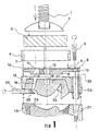
- the injector is made up of the hollow upper cylindrical part (4) and the base part (10), which are situated above the two half muffles (15, 16), both provided with screw-threaded devices (20, 21) in their interior (22) in order to facilitate the passage of the bolts (6).
- these two half muffles (15, 16) contain the moulds (17) which include the teeth (23), as well as the resin inlet duct (18) and the rod (24), by way of a nib at its inner end, that passes through slots (25) in both half muffles, cut in their contact areas.
- the upper half muffle (15) has an upper hole or mouth (14), which will be between 40 and 150 millimetres in size, as been mentioned previously.
- the two half slots (25) illustrated in this Figure 1 can be composed of one single duct cut in the upper half muffle (15), a variant that is also considered to be covered by the invention, as well as any other practical solution intended for this purpose.
- the base casing (10) is provided with the lower projection (8) so that it can be housed in the vacity or recess (14) in the upper half muffle (15).
- the trunco-conical central hole (12) is shown and the hole or holes (11) for the resins to pass through towards the duct (18) of the mould (17).
- this base casing (10) In the upper face of this base casing (10) appears the circular ledge (9) that determines the groove, from the base of which the holes (11) and (12) begin.
- the circular recess (7) of the cylindrical casing (4) becomes seated on this ledge (9).
- the base casing Replacement (10) is provided with the devices (5) provided with drill holes (13) to allow bolts (6) to pass through, which secure the said casing to the half muffles.
- the invention also covers the fact that the hollow cylindrical casing (4) can also be provided with similar devices drilled in harmony with those mentioned (5, 13), and even the fact that these devices with drill holes can be carried out only in the casing (4).
- Figure 2 allows us to appreciate the top view of the injector, with the hollow cylindrical casing (4) and the base casing (10), and with the devices (5) drill holed at (13) for the bolts to pass through.
- Figure 3 represents particularly the rod (24) with its end cut-out (26) in a concave shape in order to facilitate the passage or flow of the resin in the way described in relation to Figure 1.
- the operation of the injector is extremely simple, and beings with the arranging of the two half muffles (15, 16) containing the prosthesis (17), with the rod (24) being arranged in the slots (25) in the said half muffles, precisely in the position illustrated in Figure 1.
- the base part (10) is situated over the half muffle (15) and secured to it by means of the bolts (6).
- the hollow cylindrical casing (4) is fitted onto the base casing, and the cavity in the casing (4) is filled with resin, with resin, with the piston (3) being arranged over the resin, after which the pusher plate (2) of the press is applied, being operated by means of the screw-spindle (1).
Landscapes
- Health & Medical Sciences (AREA)
- Oral & Maxillofacial Surgery (AREA)
- Dentistry (AREA)
- Epidemiology (AREA)
- Life Sciences & Earth Sciences (AREA)
- Animal Behavior & Ethology (AREA)
- General Health & Medical Sciences (AREA)
- Public Health (AREA)
- Veterinary Medicine (AREA)
- Injection Moulding Of Plastics Or The Like (AREA)
- Prostheses (AREA)
- Processing And Handling Of Plastics And Other Materials For Molding In General (AREA)
- Dental Tools And Instruments Or Auxiliary Dental Instruments (AREA)
Claims (6)
- Ein System einer Harzdüse, bestehend aus einer Muffel (15, 16), einer Presse (1, 2, 3, 4), bestehend aus einem Kolben (3), einer Schraubenspindel (1), einer Druckplatte (2) am Ende der Spindel (1) und einem hohlzylindrischen Gehäuse (4), wobei besagte Muffel aus zwei Gehäusehälften (15, 16) besteht, von denen jede mit Schraubgewinde-Öffnungen (20, 21) versehen ist, die einander für die Aufnahme von Verbindungsschrauben (6) zur Befestigung besagter Gehäusehälften entsprechen, von denen die oberen Hälften (15) jeweils eine Pressform (17) mit einem kreisförmigen Mundloch (14) enthalten, das durch Folgendes gekennzeichnet ist:das kreisförmige Mundloch (14) der oberen Hälfte (15) der Muffel hat einen Durchmesser von 40 bis 150 mm und ist dafür angeordnet, um einen vorstehenden unteren Hals (8) eines Basisgehäuses (10) aufzunehmen, der sich zwischen der Muffel und dem hohlzylindrischen Gehäuse (4) der Presse befindet, wobei besagtes Gehäuse mindestens eine exzentrische Durchgangsbohrung (11) enthält, die der Position eines Harz-Durchlasskanals (18) entspricht, der in die Pressform (17) der Muffel eingeschnitten ist, mit einem zentrierten kreisförmigen Absatz (9) auf seiner Oberseite,besagtes hohlzylindrisches Gehäuse (4) besitzt eine ringförmige Vertiefung (7) zur Aufnahme von besagtem zentrierten kreisförmigen Absatz (9) des Gehäuses (10), sowie Schraubgewinde-Öffnungen (13), die den Öffnungen (20, 21) der Muffel entsprechen,besagtes hohlzylindrischen Gehäuse (4) besitzt eine ringförmige Vertiefung (7) zur Aufnahme von besagtem zentrierten kreisförmigen Absatz (9) des Gehäuses (10) und bildet daher eine Kammer zur Aufnahme des Harzes,die zwei Gehäusehälften (15, 16) der Muffel besitzen auf ihrer Kontaktoberfläche jeweils mindestens ein Paar radialer Kerben (25) mit halbkreisförmigen Querschnitten, wobei besagte Kerben mit besagtem Harz-Durchlasskanal (18) verbunden sind und so angeordnet sind, dass sie mindestens einen Stab (24) von der Außenseite aufnehmen, und ein inneres Ende des besagten Stabs eine Aussparung (26) aufweist, wobei besagter Stab (24) so angeordnet ist, dass er den Harz-Durchlasskanal (18) der Pressform (17) öffnet und schließt.
- Harzdüse mit Muffel, in Übereinstimmung mit Anspruch 1, die dadurch gekennzeichnet ist, dass das hohlzylindrische Gehäuse (4) auch mit perforierten Schraubgewindevorrichtungen versehen ist, die mit jenen in dem Basisgehäuse-Ersatzteil (10) und mit jenen in den zwei halben Muffeln übereinstimmen.
- Harzdüse mit Muffel, in Übereinstimmung mit Anspruch 1, die dadurch gekennzeichnet ist, dass das Basisgehäuse nicht mit perforierten Schraubgewindevorrichtungen (5, 13) versehen ist, wobei diese lediglich in das hohlzylindrische Gehäuse (4) eingeschnitten sind.
- Harzdüse mit Muffel, in Übereinstimmung mit Anspruch 1, die dadurch gekennzeichnet ist, dass das Innere des hohlzylindrischen Gehäuses (4) eine variable Höhe von 10 bis 80 Millimetern und zudem einen variablen Durchmesser von 40 bis 150 Millimetern aufweist.
- Harzdüse mit Muffel, in Übereinstimmung mit Anspruch 1, die dadurch gekennzeichnet ist, dass es zwei Injektionslöcher (11) in dem Basisgehäuse-Ersatzteil (10) gibt, die nahe beieinander angeordnet sind.
- Harzdüse mit Muffel, in Übereinstimmung mit der Muffel, in Übereinstimmung mit Anspruch 1, die dadurch gekennzeichnet ist, dass der transversale Querschnitt des unteren Halses (8) der Basisgehäuse-Ersatzteile (10) und die Form des Mundlochs (14) der entsprechenden oberen halben Muffel (15) nicht kreisförmig sind.
Applications Claiming Priority (2)
| Application Number | Priority Date | Filing Date | Title |
|---|---|---|---|
| ES9601060 | 1996-05-10 | ||
| ES009601060A ES2132007B1 (es) | 1996-05-10 | 1996-05-10 | Inyector de resina con mufla |
Publications (3)
| Publication Number | Publication Date |
|---|---|
| EP0806188A2 EP0806188A2 (de) | 1997-11-12 |
| EP0806188A3 EP0806188A3 (de) | 1998-04-15 |
| EP0806188B1 true EP0806188B1 (de) | 2003-11-05 |
Family
ID=8294788
Family Applications (1)
| Application Number | Title | Priority Date | Filing Date |
|---|---|---|---|
| EP97500083A Expired - Lifetime EP0806188B1 (de) | 1996-05-10 | 1997-05-08 | Harzinjektor mit Muffel |
Country Status (4)
| Country | Link |
|---|---|
| US (1) | US5858417A (de) |
| EP (1) | EP0806188B1 (de) |
| DE (1) | DE69725919T2 (de) |
| ES (1) | ES2132007B1 (de) |
Families Citing this family (5)
| Publication number | Priority date | Publication date | Assignee | Title |
|---|---|---|---|---|
| ITPS20010026A1 (it) * | 2001-11-09 | 2003-05-09 | Pressing Dental Srl | Procedimento per convertire all' impiego di resine acetaliche e simili un dispositivo per produzione di protesi |
| DE202005003014U1 (de) * | 2005-02-24 | 2005-04-28 | Dekema Dental-Keramiköfen GmbH | Vorrichtung zur Herstellung von Muffeln für die Herstellung von Zahnersatzteilen |
| DE102008017784B4 (de) * | 2008-04-08 | 2014-04-17 | Ivoclar Vivadent Ag | Vorrichtung zum Anfertigen einer Muffel |
| DE102010061609A1 (de) * | 2010-12-29 | 2012-07-05 | Bredent Gmbh & Co. Kg | Verfahren zur Herstellung von zahnprothetischen Formkörpern und Muffelsystem dafür |
| WO2017177049A1 (en) * | 2016-04-06 | 2017-10-12 | Glas-Weld Systems, Inc. | Windshield and laminated glass repair tool |
Family Cites Families (9)
| Publication number | Priority date | Publication date | Assignee | Title |
|---|---|---|---|---|
| US2474105A (en) * | 1947-04-19 | 1949-06-21 | Hordes Irving | Apparatus for casting dental restorations |
| US2576224A (en) * | 1948-12-08 | 1951-11-27 | Hordes Irving | Apparatus for casting dental restorations |
| US2806253A (en) * | 1953-10-19 | 1957-09-17 | Harold M Vernon | Method and apparatus for the production of prostheses such as dentures |
| US2790998A (en) * | 1953-11-20 | 1957-05-07 | Toledo Dental Products Company | Molding method |
| JPH0771564B2 (ja) * | 1988-11-02 | 1995-08-02 | 博 木村 | レジン義歯床の製造方法 |
| US5175008A (en) * | 1988-11-24 | 1992-12-29 | Chugoku Shiken Kabushiki Kaisha | Device for supplying plastic material for denture base and flask with the same |
| EP0370496B1 (de) * | 1988-11-24 | 1994-04-20 | Chugoku Shiken Kabushiki Kaisha | Kunststoffzuführvorrichtung für Zahnstützvorrichtung und damit versehener Formkosten |
| US5302104A (en) * | 1992-06-18 | 1994-04-12 | High Dental Service Co., Ltd. | Resin denture base molding apparatus |
| ES1027833Y (es) * | 1994-05-04 | 1995-03-01 | Beltran Gregorio Atienza | Mufla perfeccionada |
-
1996
- 1996-05-10 ES ES009601060A patent/ES2132007B1/es not_active Expired - Lifetime
-
1997
- 1997-05-08 DE DE69725919T patent/DE69725919T2/de not_active Expired - Fee Related
- 1997-05-08 EP EP97500083A patent/EP0806188B1/de not_active Expired - Lifetime
- 1997-05-12 US US08/854,539 patent/US5858417A/en not_active Expired - Fee Related
Also Published As
| Publication number | Publication date |
|---|---|
| DE69725919D1 (de) | 2003-12-11 |
| ES2132007A1 (es) | 1999-08-01 |
| US5858417A (en) | 1999-01-12 |
| ES2132007B1 (es) | 2000-04-16 |
| DE69725919T2 (de) | 2004-05-13 |
| EP0806188A3 (de) | 1998-04-15 |
| EP0806188A2 (de) | 1997-11-12 |
Similar Documents
| Publication | Publication Date | Title |
|---|---|---|
| CA1042164A (en) | Interchangeable mold assembly | |
| CA1106565A (en) | Method and apparatus for venting entrapped air in mold cavities | |
| KR20000071063A (ko) | 두 성분으로 구성된 물품을 제조하기 위한 사출 성형 방법 및 장치 | |
| CZ20011265A3 (cs) | Způsob rotačního odlévání a zařízení k provádění tohoto způsobu | |
| US4382785A (en) | Multiple inlet dental impression tray | |
| CA2307479A1 (en) | Mold and molding machine for making ophthalmic devices | |
| BR0315398A (pt) | Sistema de inserto de molde para um aparelho de moldar por injeção | |
| AU2347200A (en) | Method for side-fill lens casting | |
| EP0806188A2 (de) | Harzinjektor mit Muffel | |
| WO2002093103A1 (fr) | Douille de cartouche en plastique et dispositif servant a sa fabrication | |
| US5893405A (en) | Triangular spoke sprue | |
| CA2190569A1 (en) | Injection molding nozzle with edge gate inserts and sealing ring | |
| EP0426096A2 (de) | Rotationsmaschine zum Spritz-Streck-Blasformen | |
| US4948359A (en) | Mold holding and positioning means for use with wax injector | |
| US5066213A (en) | Wax-casting components | |
| AU6073190A (en) | Procedure and machinery for the production of an assembled object | |
| GB2331724A (en) | Injection molding form and process for producing hollow parts | |
| US4025269A (en) | Mold structure and cavity forming insert arrangement therefor | |
| JP4005553B2 (ja) | マッフルシステム | |
| CA2122484A1 (en) | Multi-mold centrifugal casting apparatus | |
| US5281122A (en) | Vessel for duplicating dental models | |
| CA2120880A1 (en) | Injection molding method and apparatus for preparing dental prosthesis and medical devices | |
| JP3090157B2 (ja) | バルブゲート式金型装置 | |
| US3302257A (en) | Method for casting rings by the lost wax process | |
| US1595338A (en) | Dental casting device |
Legal Events
| Date | Code | Title | Description |
|---|---|---|---|
| PUAI | Public reference made under article 153(3) epc to a published international application that has entered the european phase |
Free format text: ORIGINAL CODE: 0009012 |
|
| AK | Designated contracting states |
Kind code of ref document: A2 Designated state(s): DE FR IT |
|
| PUAL | Search report despatched |
Free format text: ORIGINAL CODE: 0009013 |
|
| AK | Designated contracting states |
Kind code of ref document: A3 Designated state(s): DE FR IT |
|
| 17P | Request for examination filed |
Effective date: 19980930 |
|
| 17Q | First examination report despatched |
Effective date: 20010911 |
|
| GRAG | Despatch of communication of intention to grant |
Free format text: ORIGINAL CODE: EPIDOS AGRA |
|
| GRAG | Despatch of communication of intention to grant |
Free format text: ORIGINAL CODE: EPIDOS AGRA |
|
| GRAH | Despatch of communication of intention to grant a patent |
Free format text: ORIGINAL CODE: EPIDOS IGRA |
|
| GRAS | Grant fee paid |
Free format text: ORIGINAL CODE: EPIDOSNIGR3 |
|
| GRAA | (expected) grant |
Free format text: ORIGINAL CODE: 0009210 |
|
| AK | Designated contracting states |
Kind code of ref document: B1 Designated state(s): DE FR IT |
|
| REF | Corresponds to: |
Ref document number: 69725919 Country of ref document: DE Date of ref document: 20031211 Kind code of ref document: P |
|
| ET | Fr: translation filed | ||
| PLBE | No opposition filed within time limit |
Free format text: ORIGINAL CODE: 0009261 |
|
| STAA | Information on the status of an ep patent application or granted ep patent |
Free format text: STATUS: NO OPPOSITION FILED WITHIN TIME LIMIT |
|
| 26N | No opposition filed |
Effective date: 20040806 |
|
| PGFP | Annual fee paid to national office [announced via postgrant information from national office to epo] |
Ref country code: IT Payment date: 20080515 Year of fee payment: 12 |
|
| PGFP | Annual fee paid to national office [announced via postgrant information from national office to epo] |
Ref country code: DE Payment date: 20080630 Year of fee payment: 12 |
|
| PGFP | Annual fee paid to national office [announced via postgrant information from national office to epo] |
Ref country code: FR Payment date: 20080523 Year of fee payment: 12 |
|
| REG | Reference to a national code |
Ref country code: FR Ref legal event code: ST Effective date: 20100129 |
|
| PG25 | Lapsed in a contracting state [announced via postgrant information from national office to epo] |
Ref country code: FR Free format text: LAPSE BECAUSE OF NON-PAYMENT OF DUE FEES Effective date: 20090602 |
|
| PG25 | Lapsed in a contracting state [announced via postgrant information from national office to epo] |
Ref country code: DE Free format text: LAPSE BECAUSE OF NON-PAYMENT OF DUE FEES Effective date: 20091201 |
|
| PG25 | Lapsed in a contracting state [announced via postgrant information from national office to epo] |
Ref country code: IT Free format text: LAPSE BECAUSE OF NON-PAYMENT OF DUE FEES Effective date: 20090508 |