EP0806155B1 - Dispositif de pliage des bords d'une empeigne sur une forme d'une machine pour la fabrication de chaussures - Google Patents
Dispositif de pliage des bords d'une empeigne sur une forme d'une machine pour la fabrication de chaussures Download PDFInfo
- Publication number
- EP0806155B1 EP0806155B1 EP19960830263 EP96830263A EP0806155B1 EP 0806155 B1 EP0806155 B1 EP 0806155B1 EP 19960830263 EP19960830263 EP 19960830263 EP 96830263 A EP96830263 A EP 96830263A EP 0806155 B1 EP0806155 B1 EP 0806155B1
- Authority
- EP
- European Patent Office
- Prior art keywords
- folding
- last
- insole
- rig according
- onto
- Prior art date
- Legal status (The legal status is an assumption and is not a legal conclusion. Google has not performed a legal analysis and makes no representation as to the accuracy of the status listed.)
- Expired - Lifetime
Links
- 238000004519 manufacturing process Methods 0.000 title claims description 4
- 238000004873 anchoring Methods 0.000 claims description 8
- 239000004568 cement Substances 0.000 description 4
- 230000002045 lasting effect Effects 0.000 description 3
- 230000007246 mechanism Effects 0.000 description 2
- 230000006978 adaptation Effects 0.000 description 1
- 230000002411 adverse Effects 0.000 description 1
- 230000001419 dependent effect Effects 0.000 description 1
- 239000012530 fluid Substances 0.000 description 1
- 230000003100 immobilizing effect Effects 0.000 description 1
Images


Classifications
-
- A—HUMAN NECESSITIES
- A43—FOOTWEAR
- A43D—MACHINES, TOOLS, EQUIPMENT OR METHODS FOR MANUFACTURING OR REPAIRING FOOTWEAR
- A43D21/00—Lasting machines
- A43D21/003—Lasting machines with lasting strings, stretching straps or the like, for forming the shank portions of shoes
Definitions
- the present invention relates to a rig for folding the edge of the upper onto a last in a footwear manufacturing machine.
- machines which provide for the cementing of the edge of the upper to the insole in the area of the forepart of the shoe.
- Such machines comprise a support on which is positioned a shoemaker's last, to which the insole is applied and onto which the upper is tautened, a series of clasps which grip and stretch the upper, members which secure the last on the support, devices which deposit cement on the insole in the area of the forepart of the shoe, and two articulated plates which provide in said fore-region for the folding of the upper, released by the clasps, onto the insole of the shoe for cementing.
- the articulated plates have inner edges which interfere with the upper on the last in order to perform the folding.
- To assist the plates there are provided two opposing lateral pads which are brought against the upper laterally in the middle part of the shoe and which hold the upper pressed against the last in order to aid the folding of the upper by the plates in proximity to this middle region.
- the reason for this is that the folding of the upper in proximity to this middle region is very critical for the profile which the shoe has in this region and that, especially in certain types of footwear, the rear part is fairly rigid and adversely affects the folding.
- Document GB-A-1154871 discloses a footwear manufacturing machine comprising a rig for folding the edge of the upper over a last.
- the folding rig comprises a pair of forepart wipers which are advanced and closed to wipe the upper inwardly over the edge of the forepart of the insole.
- For lasting the shank portion of the shoe the machine is provided with a pair of lasting units carried on the ends of piston rod extending from fluid operated cylinders.
- Each lasting unit comprises a resilient band (56) which extends over and between two legs, the band being secured by a clamp.
- the object of the present invention is to overcome the aforesaid drawbacks.
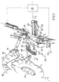
- the folding rig illustrated operates in a machine for making footwear of the type indicated in the introduction, that is, one comprising a support on which is positioned a shoe last to which the insole is applied and over which the upper is tautened, a series of clasps which grip and stretch the upper, members which secure the last on the support, and devices which deposit cement on the insole in the area of the forepart of the shoe.
- the folding rig comprises two plates 10 which articulate around a common centre of rotation and which are actuated by suitable mechanisms, partially visible in the figures, in such a way as to move and rotate, and thus to operate on the forepart of the shoe.
- each plate 10 has a wedge 11.
- the folding rig moreover comprises two auxiliary devices 20 arranged on opposite sides with respect to the support on which the last A is positioned.
- Each device 20 is mounted on a bed 21 of the machine, visible in Fig. 1 only, on which is mounted a pneumatic actuator 22 fitted with an actuating rod 23 operating along a direction X substantially perpendicular to the axis Y of the last A positioned on the support, and in the vicinity of a middle part of the shoe.
- the rod 23 is integral with a substantially "C"-shaped support 24 mounted perpendicularly to the rod.
- the bottom arm of the support 24 is fixed to the rod 23, while the top arm of the support 24 carries, elastically, a further arm 25 which extends parallel to the rod 23 towards the last A; in particular, the arm 25 is hinged at 36 in a block 37 at the end of the top arm of the support 24, and a spring 38 mounted on a screw 39 screwed into the block 37 keeps the arm 25 elastically in position.
- the rod 23 and the arm 25 carry two respective anchoring heads 26 and 27 integrally at their free ends.
- the ends of a flexible tape 28 are fixed to the heads 26 and 27 in such a way that the tape is tensioned between the said heads.
- the forward or backward movement of the rod 23 clearly involves an identical movement of the tape 28.
- a bar 29 parallel to the rod 23 and fitted, in proximity to its other end, with a tooth 30, is fixed to the bottom arm of the "C"-shaped support 24, at one end.
- an arresting contrivance 31 comprising a pawl 32 intended to interfere with the tooth 30 of the bar 29, actuated by a pneumatic actuator 33 and restored to the rest position by a spring 34.
- An electronic facility 35 shown diagrammatically in Fig. 1 only, is also envisaged and provides for coordinating the movements of the plates 10, of the auxiliary devices 20 controlling the actuating of the actuators 22 and 33, and of the other members, not illustrated, of the machine.
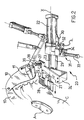
- the two tapes 28 are firstly moved forward by the actuators 22, followed by the plates 10, so as to reach, starting from the initial position illustrated in Figs. 1 and 4, an intermediate position illustrated in Figs. 2 and 5.
- the tapes 28 reach this intermediate position by virtue of the immobilizing of the teeth 30 against the pawls 32. After these operations cement is placed on the insole B.
- the devices 20 are obviously simple and hence highly reliable.
- tapes 28 can adapt to lasts of various shape, given their flexibility.
- the elastic connection of the arms 25 to the "C"-shaped supports 24 makes it possible to compensate for excessive tensions in the tapes 28 during folding.
- the screws 39 enable the elastic loading of the springs 38 on the arms 25 to be adjusted.
- the position of the devices 20 on the bed 21 in a direction parallel to the axis Y can be adjusted, by for example connecting the devices to the bed via suitable guides and securing the devices in the preselected position by means of suitable securing members. This adjustment allows adaptation, in addition to that seen earlier, of the devices to lasts of different shapes.
- the arresting devices 31 turn out to be particularly advantageous for synchronizing the movements of the devices 20 with the movements of the plates 10.
- the tapes can be replaced with flexible elements which fulfil equivalent functions, supported and propelled in any manner.
- the tapes can be supported by structures of a layout other than those shown.
- the structures illustrated turn out however to be particularly simple and effective.
- actuators may be used, for example hydraulic, electric or other actuators.
- the tapes can also be elastic and in this case the elastic connection of the arms to the "C"-shaped supports can be dispensed with.
- the arresting devices can also be omitted in the case in which the electronic facility has suitable sensors to enable it to regulate the movement of the tapes with the movement of the plates.
- Such securing devices turn out however to be particularly simple and effective.
Landscapes
- Footwear And Its Accessory, Manufacturing Method And Apparatuses (AREA)
Claims (11)
- Dispositif de pliage du bord de l'empeigne sur une forme, dans une machine de fabrication de chaussures qui prévoit de supporter la forme (A), sur laquelle la semelle intérieure (B) est appliquée, et sur laquelle l'empeigne (C) est tendue, de serrer et étirer l'empeigne (C) et de garder la forme (A) fixée, comprenant :caractérisé en ce que lesdits moyens (10, 11) pour plier l'empeigne (C) sur la semelle intérieure (B) sont mobiles entre une position dans laquelle ils sont éloignés de l'empeigne (C) et une position dans laquelle ils agissent sur l'empeigne et sur les éléments flexibles (28) lorsque lesdits éléments flexibles (28) sont dans la position avancée.des moyens (10, 11) pour plier l'empeigne (C) sur la semelle intérieure (B) dans la zone de l'avant-pied de la chaussure afin de fixer l'empeigne à la semelle intérieure, etdes éléments flexibles (28) agencés sur les côtés opposés de la forme (A) au voisinage d'une partie centrale de la chaussure qui sont mobiles entre une position rétractée dans laquelle ils sont éloignés de la forme (A) et une position avancée dans laquelle ils enserrent les flancs de la forme (A), de manière à plier l'empeigne (C) sur la semelle intérieure (B),
- Dispositif de pliage selon la revendication 1, dans lequel chaque élément flexible comprend une bande (28) supportée et tendue à ses extrémités par deux têtes d'ancrage (26, 27) reliées à une tige (23) d'un organe d'actionnement (22) et lesdits moyens (10, 11) pour plier l'empeigne (C) sur la semelle intérieure (B) se déplacent pour s'insérer entre lesdites deux têtes d'ancrage (26, 27) afin d'agir sur la bande (28) durant l'opération de pliage de l'empeigne (C) sur la semelle intérieure (B).
- Dispositif de pliage selon la revendication 2, dans lequel une première tête d'ancrage (27) desdites deux têtes d'ancrage (26, 27) est fixée à l'extrémité libre de la tige (23) et se déplace vers et depuis la forme (A) le long d'une direction (X) qui est perpendiculaire à l'axe (Y) de la forme (A) et se situe dans le plan de la semelle intérieure (B) appliquée sur la forme (A), de manière que dans la position avancée la première tête d'ancrage (27) presse l'élément flexible contre l'empeigne (C) et donc l'empeigne (C) contre la semelle intérieure (B).
- Dispositif de pliage selon la revendication 2, comprenant un support sensiblement en forme de "C" (24) qui se situe dans un plan transversal à la tige (23) et comporte un premier bras fixé à la tige (23), tandis que la deuxième tête d'ancrage (26) est reliée à l'autre bras de l'élément en forme de "C" (24).
- Dispositif de pliage selon la revendication 4, dans lequel la connexion entre la deuxième tête d'ancrage (26) et l'élément en forme de "C" (24) est élastique.
- Dispositif de pliage selon la revendication 2, dans lequel la bande (28) est élastique.
- Dispositif de pliage selon la revendication 2, dans lequel les moyens (10, 11) de pliage sont immobilisés dans une position intermédiaire avant d'être amenés dans la position de pliage, et dans lequel est prévu, pour chaque bande, un dispositif d'arrêt (29 à 34) qui immobilise la bande (28) dans une position intermédiaire, la libérant avant le mouvement final des moyens de pliage (10, 11) dans la position de pliage.
- Dispositif de pliage selon la revendication 7, dans lequel le dispositif d'arrêt comprend une barre (29) avec une dent (30), laquelle barre est parallèle à, et d'un seul tenant avec, la tige (23), et un cliquet (32) adapté à s'engager avec la dent (30) de la barre (29), actionné entre une position d'engagement avec la dent (30) et une position de désengagement.
- Dispositif de pliage selon la revendication 1, dans lequel est prévu un dispositif électronique (35) qui synchronise les mouvements des moyens de pliage (10, 11) et des éléments flexibles (28).
- Dispositif de pliage selon la revendication 7, dans lequel est prévu un dispositif électronique (35) qui synchronise les mouvements des moyens de pliage (10, 11), des éléments flexibles (28) et des dispositifs d'arrêt (29 à 34).
- Dispositif de pliage selon la revendication 1, dans lequel la position des éléments flexibles (28) dans une direction parallèle à l'axe (Y) de la forme (A) est réglable.
Priority Applications (4)
| Application Number | Priority Date | Filing Date | Title |
|---|---|---|---|
| PT96830263T PT806155E (pt) | 1996-05-07 | 1996-05-07 | Aparelho para dobrar o bordo da gaspea sobre uma forma de metal numa maquina de fabrico de calcado |
| ES96830263T ES2180723T3 (es) | 1996-05-07 | 1996-05-07 | Dispositivo para doblar el borde de la parte superior del zapato sobre una horma de una maquina para la fabricacion de calzado. |
| EP19960830263 EP0806155B1 (fr) | 1996-05-07 | 1996-05-07 | Dispositif de pliage des bords d'une empeigne sur une forme d'une machine pour la fabrication de chaussures |
| DE69623442T DE69623442T2 (de) | 1996-05-07 | 1996-05-07 | Vorrichtung zum Falten einer Kante des Oberleders auf einer Leiste von einer Schuhherstellungsmaschine |
Applications Claiming Priority (1)
| Application Number | Priority Date | Filing Date | Title |
|---|---|---|---|
| EP19960830263 EP0806155B1 (fr) | 1996-05-07 | 1996-05-07 | Dispositif de pliage des bords d'une empeigne sur une forme d'une machine pour la fabrication de chaussures |
Publications (2)
| Publication Number | Publication Date |
|---|---|
| EP0806155A1 EP0806155A1 (fr) | 1997-11-12 |
| EP0806155B1 true EP0806155B1 (fr) | 2002-09-04 |
Family
ID=8225903
Family Applications (1)
| Application Number | Title | Priority Date | Filing Date |
|---|---|---|---|
| EP19960830263 Expired - Lifetime EP0806155B1 (fr) | 1996-05-07 | 1996-05-07 | Dispositif de pliage des bords d'une empeigne sur une forme d'une machine pour la fabrication de chaussures |
Country Status (4)
| Country | Link |
|---|---|
| EP (1) | EP0806155B1 (fr) |
| DE (1) | DE69623442T2 (fr) |
| ES (1) | ES2180723T3 (fr) |
| PT (1) | PT806155E (fr) |
Family Cites Families (6)
| Publication number | Priority date | Publication date | Assignee | Title |
|---|---|---|---|---|
| US1517297A (en) * | 1921-05-31 | 1924-12-02 | United Shoe Machinery Corp | Lasting machine |
| US3264666A (en) * | 1965-09-03 | 1966-08-09 | United Shoe Machinery Corp | Shoe lasting machines |
| US3940816A (en) * | 1974-08-08 | 1976-03-02 | Leonhardt Horst M | Side lasting apparatus |
| DE2459101C3 (de) * | 1974-12-13 | 1978-05-24 | Deutsche Vereinigte Schuhmaschinen Gmbh, 6000 Frankfurt | Verfahren zum Zwicken von aufgeleistetem Schuhwerk im seitlichen Bereich des Schuhs sowie Vorrichtung zur Durchführung des Verfahrens |
| DE3314906A1 (de) * | 1983-04-25 | 1984-10-25 | Deutsche Vereinigte Schuhmaschinen Gmbh, 6000 Frankfurt | Verfahren und vorrichtung zum seitenzwicken von aufgeleisteten schuhen mit einer seiten-tacks-einschlagvorrichtung |
| GB8805135D0 (en) * | 1988-03-03 | 1988-03-30 | British United Shoe Machinery | Machine for lasting side portions of shoes |
-
1996
- 1996-05-07 DE DE69623442T patent/DE69623442T2/de not_active Expired - Fee Related
- 1996-05-07 ES ES96830263T patent/ES2180723T3/es not_active Expired - Lifetime
- 1996-05-07 PT PT96830263T patent/PT806155E/pt unknown
- 1996-05-07 EP EP19960830263 patent/EP0806155B1/fr not_active Expired - Lifetime
Also Published As
| Publication number | Publication date |
|---|---|
| DE69623442T2 (de) | 2003-04-30 |
| PT806155E (pt) | 2003-01-31 |
| EP0806155A1 (fr) | 1997-11-12 |
| DE69623442D1 (de) | 2002-10-10 |
| ES2180723T3 (es) | 2003-02-16 |
Similar Documents
| Publication | Publication Date | Title |
|---|---|---|
| US5722103A (en) | Toe and side and heel lasting machine and method of lasting | |
| EP0806155B1 (fr) | Dispositif de pliage des bords d'une empeigne sur une forme d'une machine pour la fabrication de chaussures | |
| US4095302A (en) | Manufacture of shoes | |
| US3995340A (en) | Shoe lasting machines | |
| US3818526A (en) | Pulling and lasting machines | |
| EP1374709A1 (fr) | Procédé pour appliquer un adhésif sur une première de montage | |
| US2754529A (en) | Breast line lasting machines | |
| EP1036516B1 (fr) | Machine pour la fabrication des chaussures. | |
| EP0162696A2 (fr) | Machine de montage des côtés et des talons de chaussures | |
| EP0338722A2 (fr) | Assemblage de rabatteurs pour machine de montage de chaussures | |
| US3775797A (en) | Method and machine for lasting | |
| GB2047072A (en) | Shank lasting wipers | |
| US4905336A (en) | Machine for lasting side portions of shoes | |
| EP0124229B1 (fr) | Machine de montage d'une empeigne de chaussure | |
| EP0247831B1 (fr) | Machine à Monter les Flancs et les Emboitages | |
| US3596302A (en) | Machine for shaping and wiping uppers over a last | |
| IE32945B1 (en) | Improvements in or relating to shoe upper conforming machines | |
| US3660857A (en) | Automatically lasting machines | |
| EP0553734A1 (fr) | Assemblage de pinces | |
| US5678269A (en) | Toe and side and heel lasting machine and method of lasting | |
| GB2210247A (en) | Method of and apparatus for pulling over and lasting footwear | |
| US3238544A (en) | Apparatus for covering shoe parts | |
| US4395790A (en) | Shoe machine | |
| WO1989008412A1 (fr) | Machine a mettre sur forme et a monter pour chaussures | |
| US2226754A (en) | Machine for operating upon stitchdown shoes |
Legal Events
| Date | Code | Title | Description |
|---|---|---|---|
| PUAI | Public reference made under article 153(3) epc to a published international application that has entered the european phase |
Free format text: ORIGINAL CODE: 0009012 |
|
| AK | Designated contracting states |
Kind code of ref document: A1 Designated state(s): BE CH DE ES FR GB IT LI NL PT |
|
| AX | Request for extension of the european patent |
Free format text: AL;LT;LV;SI |
|
| RBV | Designated contracting states (corrected) |
Designated state(s): BE CH DE ES FR GB IT LI NL PT |
|
| 17P | Request for examination filed |
Effective date: 19980212 |
|
| 17Q | First examination report despatched |
Effective date: 19990702 |
|
| RTI1 | Title (correction) |
Free format text: RIG FOR FOLDING THE EDGE OF THE UPPER ONTO A LAST IN A FOOTWEAR MANUFACTURING MACHINE |
|
| GRAG | Despatch of communication of intention to grant |
Free format text: ORIGINAL CODE: EPIDOS AGRA |
|
| RTI1 | Title (correction) |
Free format text: RIG FOR FOLDING THE EDGE OF THE UPPER ONTO A LAST IN A FOOTWEAR MANUFACTURING MACHINE |
|
| GRAG | Despatch of communication of intention to grant |
Free format text: ORIGINAL CODE: EPIDOS AGRA |
|
| GRAH | Despatch of communication of intention to grant a patent |
Free format text: ORIGINAL CODE: EPIDOS IGRA |
|
| GRAH | Despatch of communication of intention to grant a patent |
Free format text: ORIGINAL CODE: EPIDOS IGRA |
|
| RAP1 | Party data changed (applicant data changed or rights of an application transferred) |
Owner name: OFFICINE MECCANICHE MOLINA & BIANCHI S.P.A. |
|
| GRAA | (expected) grant |
Free format text: ORIGINAL CODE: 0009210 |
|
| AK | Designated contracting states |
Kind code of ref document: B1 Designated state(s): BE CH DE ES FR GB IT LI NL PT |
|
| REG | Reference to a national code |
Ref country code: GB Ref legal event code: FG4D |
|
| REG | Reference to a national code |
Ref country code: CH Ref legal event code: EP |
|
| REF | Corresponds to: |
Ref document number: 69623442 Country of ref document: DE Date of ref document: 20021010 |
|
| REG | Reference to a national code |
Ref country code: CH Ref legal event code: NV Representative=s name: R. A. EGLI & CO. PATENTANWAELTE |
|
| ET | Fr: translation filed | ||
| REG | Reference to a national code |
Ref country code: PT Ref legal event code: SC4A Free format text: AVAILABILITY OF NATIONAL TRANSLATION Effective date: 20021129 |
|
| REG | Reference to a national code |
Ref country code: ES Ref legal event code: FG2A Ref document number: 2180723 Country of ref document: ES Kind code of ref document: T3 |
|
| PGFP | Annual fee paid to national office [announced via postgrant information from national office to epo] |
Ref country code: GB Payment date: 20030417 Year of fee payment: 8 |
|
| PG25 | Lapsed in a contracting state [announced via postgrant information from national office to epo] |
Ref country code: LI Free format text: LAPSE BECAUSE OF NON-PAYMENT OF DUE FEES Effective date: 20030531 Ref country code: CH Free format text: LAPSE BECAUSE OF NON-PAYMENT OF DUE FEES Effective date: 20030531 Ref country code: BE Free format text: LAPSE BECAUSE OF NON-PAYMENT OF DUE FEES Effective date: 20030531 |
|
| PLBE | No opposition filed within time limit |
Free format text: ORIGINAL CODE: 0009261 |
|
| STAA | Information on the status of an ep patent application or granted ep patent |
Free format text: STATUS: NO OPPOSITION FILED WITHIN TIME LIMIT |
|
| 26N | No opposition filed |
Effective date: 20030605 |
|
| BERE | Be: lapsed |
Owner name: OFFICINE MECCANICHE *MOLINA & BIANCHI S.P.A. Effective date: 20030531 |
|
| PG25 | Lapsed in a contracting state [announced via postgrant information from national office to epo] |
Ref country code: NL Free format text: LAPSE BECAUSE OF NON-PAYMENT OF DUE FEES Effective date: 20031201 |
|
| REG | Reference to a national code |
Ref country code: CH Ref legal event code: PL |
|
| NLV4 | Nl: lapsed or anulled due to non-payment of the annual fee |
Effective date: 20031201 |
|
| PG25 | Lapsed in a contracting state [announced via postgrant information from national office to epo] |
Ref country code: GB Free format text: LAPSE BECAUSE OF NON-PAYMENT OF DUE FEES Effective date: 20040507 |
|
| PGFP | Annual fee paid to national office [announced via postgrant information from national office to epo] |
Ref country code: DE Payment date: 20040520 Year of fee payment: 9 |
|
| GBPC | Gb: european patent ceased through non-payment of renewal fee |
Effective date: 20040507 |
|
| PGFP | Annual fee paid to national office [announced via postgrant information from national office to epo] |
Ref country code: FR Payment date: 20050512 Year of fee payment: 10 |
|
| PG25 | Lapsed in a contracting state [announced via postgrant information from national office to epo] |
Ref country code: DE Free format text: LAPSE BECAUSE OF NON-PAYMENT OF DUE FEES Effective date: 20051201 |
|
| REG | Reference to a national code |
Ref country code: FR Ref legal event code: ST Effective date: 20070131 |
|
| PG25 | Lapsed in a contracting state [announced via postgrant information from national office to epo] |
Ref country code: FR Free format text: LAPSE BECAUSE OF NON-PAYMENT OF DUE FEES Effective date: 20060531 |
|
| PGFP | Annual fee paid to national office [announced via postgrant information from national office to epo] |
Ref country code: ES Payment date: 20080605 Year of fee payment: 13 |
|
| PGFP | Annual fee paid to national office [announced via postgrant information from national office to epo] |
Ref country code: PT Payment date: 20080519 Year of fee payment: 13 |
|
| REG | Reference to a national code |
Ref country code: PT Ref legal event code: MM4A Free format text: LAPSE DUE TO NON-PAYMENT OF FEES Effective date: 20091109 |
|
| PG25 | Lapsed in a contracting state [announced via postgrant information from national office to epo] |
Ref country code: PT Free format text: LAPSE BECAUSE OF NON-PAYMENT OF DUE FEES Effective date: 20091109 |
|
| REG | Reference to a national code |
Ref country code: ES Ref legal event code: FD2A Effective date: 20090508 |
|
| PG25 | Lapsed in a contracting state [announced via postgrant information from national office to epo] |
Ref country code: ES Free format text: LAPSE BECAUSE OF NON-PAYMENT OF DUE FEES Effective date: 20090508 |
|
| PGFP | Annual fee paid to national office [announced via postgrant information from national office to epo] |
Ref country code: IT Payment date: 20110525 Year of fee payment: 16 |
|
| PG25 | Lapsed in a contracting state [announced via postgrant information from national office to epo] |
Ref country code: IT Free format text: LAPSE BECAUSE OF NON-PAYMENT OF DUE FEES Effective date: 20120507 |