EP0806103B1 - Unterbrechung einer kommunikationsverbindung zwischen zwei endgeräten - Google Patents
Unterbrechung einer kommunikationsverbindung zwischen zwei endgeräten Download PDFInfo
- Publication number
- EP0806103B1 EP0806103B1 EP96901844A EP96901844A EP0806103B1 EP 0806103 B1 EP0806103 B1 EP 0806103B1 EP 96901844 A EP96901844 A EP 96901844A EP 96901844 A EP96901844 A EP 96901844A EP 0806103 B1 EP0806103 B1 EP 0806103B1
- Authority
- EP
- European Patent Office
- Prior art keywords
- terminal
- signal
- terminals
- predetermined
- equipment
- Prior art date
- Legal status (The legal status is an assumption and is not a legal conclusion. Google has not performed a legal analysis and makes no representation as to the accuracy of the status listed.)
- Expired - Lifetime
Links
Images

Classifications
-
- H—ELECTRICITY
- H04—ELECTRIC COMMUNICATION TECHNIQUE
- H04M—TELEPHONIC COMMUNICATION
- H04M3/00—Automatic or semi-automatic exchanges
- H04M3/42—Systems providing special services or facilities to subscribers
- H04M3/428—Arrangements for placing incoming calls on hold
-
- H—ELECTRICITY
- H04—ELECTRIC COMMUNICATION TECHNIQUE
- H04M—TELEPHONIC COMMUNICATION
- H04M1/00—Substation equipment, e.g. for use by subscribers
- H04M1/57—Arrangements for indicating or recording the number of the calling subscriber at the called subscriber's set
-
- H—ELECTRICITY
- H04—ELECTRIC COMMUNICATION TECHNIQUE
- H04M—TELEPHONIC COMMUNICATION
- H04M3/00—Automatic or semi-automatic exchanges
- H04M3/20—Automatic or semi-automatic exchanges with means for interrupting existing connections; with means for breaking-in on conversations
-
- H—ELECTRICITY
- H04—ELECTRIC COMMUNICATION TECHNIQUE
- H04M—TELEPHONIC COMMUNICATION
- H04M11/00—Telephonic communication systems specially adapted for combination with other electrical systems
- H04M11/08—Telephonic communication systems specially adapted for combination with other electrical systems specially adapted for optional reception of entertainment or informative matter
- H04M11/085—Telephonic communication systems specially adapted for combination with other electrical systems specially adapted for optional reception of entertainment or informative matter using a television receiver, e.g. viewdata system
Definitions
- the present invention relates to interruption temporary communication between first and second terminals in order to transmit by through equipment such as a switching crossed by the communication between the first and second terminals, data to the first terminal before re-establishing communication.
- the data to be transmitted include for example characters identifying a third calling terminal the first terminal receiving the data.
- the present invention relates more particularly a temporary interruption of a communication via a telephone network analog.
- the switching center which directly serves the first terminal temporarily interrupt communication between first and second telephone terminals when the switching center receives a call signal from third terminal. Then the switching center transmits a user alert signal to the first telephone terminal in the form of a signal audible by the user of the first terminal.
- the consequences of the disturbance are including definitive communication breakdowns telematics or mixed, non-detections and false detections of temporary interruption.
- the switching center does not distinguish the type of communication to be interrupted, and must ability to interrupt any type of communication depending one process.
- the present invention aims to provide a method temporary interruption of a communication, which is compatible with telematic communications and mixed, while remaining compatible with telephone communications.
- the first and second signals of silence correct any false signal detection terminal alert since this one is completely separate from any other signal, and so make it easier to detect the terminal compared to the prior art.
- the search for the reason is conditioned by the prior receipt of user alert signal and followed by detection of the signal modulating the carrier frequency predetermined.
- the method interrupt management includes the step of trigger a disconnect delay prior to the steps to search for the signal user alert and search for the reason.
- the disconnect delay is maximum duration loss of signal modulating the carrier frequency predetermined beyond which the first terminal breaks established communication.
- the first terminal reestablishes communication with the second terminal if the signal modulating the carrier frequency predetermined is found and if no signal user alert or no reason is detected.
- Disconnection time limit duration communication interruption to a value less than a duration causing the interruption final communication.
- the interrupt management method includes the step of transmitting an acknowledgment signal reception by the first terminal when said pattern was detected in the step of searching for the pattern.
- the step of looking for frequency loss carrier makes it possible to verify that the reception of data is complete and it is then possible to re-establish the communication in progress.
- the user alert signal is a sinusoidal signal having a frequency of 440 Hz
- the terminal alert signal is made up of two sinusoidal signals of respective frequency of 2130 Hz and 2750 Hz. These signals are easily recognizable by a large number of terminals, including telephone terminal. The frequencies of terminal alert signal can be noticeably included in the signal frequency band exchanged between the first and second terminals without to do this disturb the interruption process.
- the communication between the first and second terminal is not interrupted during a duration greater than a limit causing the permanent interruption of communication.
- the succession of silence and warning signals of terminal and silence forms the pattern to recognize by the terminal.
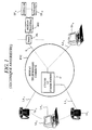
- a public or private PSTN network connects a plurality of terminals, of which four TA 1 , ... TA i , TA j , ... TA k are represented, by respective analog lines LA 1 ,. ... LA i , LA j , ... LA k .
- the PSTN network is for example the public switched analogue telephone network and comprises equipment suitable for allowing communications between subscriber terminals.
- This equipment includes switching centers and transmission circuits.
- FIG. 1 only a switching center C on which the terminals TA i and TA j depend has been shown.
- the invention is also applied to a private network comprising a private branch exchange, functionally equivalent to the switching center C in the context of the invention, subscriber terminals also being connected to the private branch exchange.
- the invention is applied to terminals connected by dedicated lines with two or four wires on which an item of equipment is placed in series and is traversed by the communication.
- the subscriber terminals TA 1 and TA j are telephone terminals.
- the subscriber terminals TA i and TA k are data terminals incorporating a modem.
- the terminals TA i and TA k can be videotex terminals such as Minitel (registered trademark) terminals and / or fax machines.
- the PSTN telephone network is also connected to VIDEOTEX Access Points (PAVI), by telephone lines.
- a videotex access point PA and a telephone line L are shown in FIG. 1.
- the access point PA adapts the signals exchanged between the PSTN telephone network and a RTI data processing network such as the packet switching network TRANSPAC (brand Mark).
- the RTI network is linked to data processing servers ST 1 to ST N.
- Communications pass through the network PSTN telephone, and more specifically by at least one switching center such as the center of switching C.
- the method involves interworking between the switching center C and the telephone terminal TA j .
- the switching center C proceeds to an interruption INT of the analog link between the telephone terminals TA 1 and TA j , while maintaining the physical link so as not to break the communication.
- the telephone terminal TA 1 is not directly involved in the process.
- the telephone terminal TA 1 is isolated from the other terminals for the duration of data transmission by the telephone switching center C and does not perceive anything during the course of the data transmission.
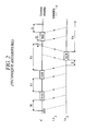
- the switching center C After the interruption INT of the analog link between the telephone terminals TA 1 and TA j , the switching center C triggers a time delay W having a duration of approximately 55 ms.
- the time delay W is a duration of silence at the end of which the switching center C transmits an audible user alert signal SAU to the telephone terminal TA j .
- the user alert signal is equivalent to a call signal, also called call waiting indicator.
- the user alert signal SAU is a sinusoidal signal with a frequency of approximately 440 Hz and has a duration of between 250 and 1000 ms. The user of the telephone terminal TA j perceives the alert signal SAU.
- switching center C After transmission of the alert signal user SAU, switching center C transmits a SAT terminal alert signal consisting of two sinusoidal signals whose frequencies are in the upper part of the telephone strip, i.e. approximately 2130 Hz and 2750 Hz.
- SAT terminal has a duration between 80 and 85 ms.
- the user alert signal SAU and the alert signal of terminal SAT are separated by a time delay X1 whose duration is between 0 and 50 ms.
- the switching center C After having transmitted the terminal alert signal SAT, the switching center C triggers a time delay T1, the duration of which is approximately 160 ms. During the time delay T1, the switching center C waits for an acknowledgment message ACK transmitted by the telephone terminal TA j .
- the telephone terminal TA j includes a detection circuit for detecting the terminal alert signal SAT. After detecting the terminal alert signal SAT, the detection circuit isolates the telephone handset from the telephone terminal TA j , that is to say isolates the microphone and the earpiece from the handset from the telephone line LA j , to the user of the telephone terminal does not hear tones corresponding to data transmission by ear and inhibits any dialing from the keyboard of the terminal TA j .
- the telephone terminal TA j transmits to the switching center C the acknowledgment message ACK which is composed of a DTMF code formed by two sinusoidal signals of frequencies equal to 941 Hz and 1,633 Hz.
- the acknowledgment message of ACK reception has a duration of approximately 60 ms and is transmitted after a time delay E between 0 and 100 ms triggered by the detection circuit in response to the terminal alert signal SAT.
- the switching center C After having received the acknowledgment message ACK during the time delay T1, the switching center C transmits a data message MD to the telephone terminal TA j after a waiting time delay Q comprised between 0 and 500 ms. An additional delay S between 0 and 120 ms is triggered at the end of the transmission of the data message MD. At the end of the time delay S, the switching center C re-establishes the analog link between the telephone terminals TA 1 and TA j so that the temporarily interrupted conversation resumes.
- the duration of the interruption between the INT interruption and the expiration of the timer S is a maximum of 1.2 seconds, to which are added the duration of the user alert signal SAU and the duration of the data message MD transmitted by switching center C.
- the telephone terminal TA j After receiving the MD data message or after a delay TA waiting for the MD data message of approximately 500 ms triggered after the transmission of the acknowledgment message ACK, the telephone terminal TA j switches the telephone line to the combined, authorizes dialing from the keyboard and uses the MD data message received, for example by displaying a message to the user on a screen.
- the message displayed declares the identity of the calling telephone terminal, for example in the form of a name or a telephone number.
- the switching center C triggers a time delay T1. If the switching center C does not receive an acknowledgment message ACK during the time delay T1, the switching center re-establishes the analog link between the telephone terminals TA 1 and TA j .
- the subscriber terminals during a call are not telephone terminals, but for example the data terminals TA i and TA k (FIG. 1), the method according to the prior art cannot be implemented without disturbing the data communication in progress.
- the data terminal TA i is connected to the subscriber telephone line LA i via a duplexer DX.
- the DX duplexer is connected to an MDM modem.
- a data processing circuit TRD is associated with a keyboard CL and a display circuit VS for processing data to be transmitted and received via the subscriber telephone line LA i via the modem MDM.
- the terminals likely to communicate between them have similar structures.
- their modems are able to communicate according to predetermined protocols and speed defined by one of the CCITT recommendations.
- terminals TA i and TA k are terminals of the Minitel type and communicate with each other by means of modems operating according to the recommendation V23 of the CCITT. Communication passes through switching center C.
- the terminal TA k transmits to the terminal TA i an indication in the form of a sequence of characters to indicate that the terminal TA k accepts the loss of the signal transmitted by the terminal TA i during a duration greater than the maximum duration necessary for a temporary interruption.
- This sequence is for example analogous to the sequence called in videotex "IAN Transpac" and composed of five bytes coded in hexadecimal in the form 1Bh, 20h, 2Xh, 2Yh, 30h where X and Y are parameters.
- the switching center C temporarily interrupts the communication in progress between the terminals TA i and TA k to transmit data to the terminal TA i when the latter is a called terminal.
- the interruption is for example caused by the call of a third data terminal which seeks to enter into communication with the terminal TA i .
- the terminal TA i is not designed to receive data during the interruption of a main data communication.
- the switching center C interrupts the communication between the terminals TA i and TA k , the modem of the terminal TA i , respectively TA k , no longer detects the energy in a predetermined frequency band of the signal modulating a carrier frequency, transmitted from the terminal modem TA k , respectively TA i .
- the switching center C transmits to the terminal TA i successively the user alert signal SAU and the terminal alert signal SAT as explained with reference to FIG. 2.
- the terminal called TA i does not recognize the signal SAU and SAT alert, and does not respond with the ACK acknowledgment message.
- the switching center C re-establishes the analog link between the terminals TA i and TA k .
- the terminals TA i and TA k seek to re-establish communication between them.
- the duration of non-detection of the transmitted signal from the start of the INT interruption until the expiration of the timer T1 is greater than a maximum admissible disconnection duration TD, fixed at 430 ms after which the non-detection of the transmitted signal causes the definitive rupture of the connection. Communication between the terminals TA i and TA k is therefore not restored.
- the terminal called TA i is designed to detect the terminal alert signal SAT and receive a data message MD during the interruption of a main data communication, that is to say during the interruption of a data signal transmitted from the terminal TA k to the terminal TA i .
- the terminal TA i can continue to transmit a data signal, intended for the terminal TA k , which will be interrupted by the data center. switching C.
- the terminal alert signal SAT is difficult to detect in the data terminal TA i with a satisfactory success rate.
- the subscriber terminal TA i when the subscriber terminal TA i is designed to transmit and receive data according to one of the recommendations V23, V27ter and V29 of the CCITT, the data signal transmitted during the main communication has a high power at the signal frequencies SAT terminal alert. Due to the inevitable coupling between transmission and reception channels VE and VR in the duplexer DX of the terminal TA i , part of the data signal transmitted in the transmission channel VE is fed back into the reception channel VR and disturbs the SAT terminal alert signal transmitted by the switching center C which may wrongly cause a failure to detect the SAT signal.
- the terminal TA i monitors the reception of a terminal alert signal SAT without knowing when such a signal will be transmitted to it.
- the frequencies of the terminal alert signal SAT are in the frequency band of the data signal transmitted by the terminal TA k which may wrongly cause detection of the terminal alert signal SAT during the main data communication.
- the terminal TA i is designed to receive a data message during a temporary interruption
- the terminal TA k does not accept the loss of the signal transmitted by the terminal TA i during the duration of the temporary interruption.
- the communication between the terminals TA i and TA k is permanently interrupted.
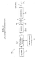
- the switching center C interrupts the analog link between the terminals TA i and TA k .
- This first temporary interruption INT1 is only intended to transmit the user alert signal SAU.
- the switching center C starts the time delay W, transmits the user alert signal SAU to the terminal called TA i then starts the time delay X1.
- the switching center C After the time delay X1, the switching center C re-establishes the analog link between the terminals TA i and TA k during a time delay TC1 having a duration of between approximately 250 and 500 ms.
- the interruption has a duration of less than 430 ms, and corresponds to the sum of the timers W and X1 and the duration of the user alert signal SAU.
- the time delay W is between approximately 0 and 50 ms
- the signal SAU is composed of a sinusoidal signal at the frequency of 440 Hz and has a duration of approximately 300 ms
- the time delay X1 is between approximately 0 and 50 ms.
- the main data communication between the terminals TA i and TA k is thus re-established during the time delay TC1 since the duration of loss of carrier frequency is less than the limit TD fixed at 430 ms beyond which the terminal TA i considers as definitively lost.
- the carrier frequency received and releases the line LA i .
- the switching center C After the time delay TC1, the switching center C again interrupts the analog link between the terminals TA i and TA k .
- the switching center C triggers a time delay TC2 of a duration equal to approximately 110 ms, then transmits the terminal alert signal SAT to the terminal TA i .
- the terminal alert signal SAT is composed of two sinusoidal signals of frequencies equal to approximately 2130 Hz and 2750 Hz.
- At least one of these carrier frequencies can be located in the frequency band of the signals transmitted between the terminals TA i and TA k when the latter are in communication, thanks to the time delay TC2 succeeding the reestablishment of the link during the time delay TC1 and the time delay T1 following the terminal alert signal SAT .
- the duration TC3 of the SAT terminal alert signal is between approximately 80 and 85 ms.
- the switching center C After the transmission of the terminal alert signal SAT, the switching center C triggers the time delay T1 of duration equal to approximately 160 ms during which the switching center C waits for the acknowledgment message ACK from the terminal TA i .
- the switching center C After having received the acknowledgment message ACK, the switching center C starts the time delay Q of duration between 0 and 100 ms, transmits the data message MD to the terminal TA i via a modem then stops the transmission of the modem carrier frequency and causes silence on the line LA i during a time delay TC7 between approximately 50 and 100 ms. After the time delay TC7 the switching center C re-establishes the link between the terminals TA i and TA k .
- the switching center C If the switching center C does not receive the acknowledgment message ACK during the time delay T1, the switching center immediately re-establishes the analog link between the terminals TA i and TA k .
- Timers TC2, T1 and TC7 are silence times during which the signal level in the line LA i has a power lower than the weakest level of the signals exchanged between the terminals TA i and TA k in communication in a frequency band Audible preferably between 1000 and 3000 Hz. Silence during the time delay TC2 is necessary for the terminal TA i to detect the terminal alert signal SAT whatever the recommendation of the CCITT applied for the communication in progress.
- the silence during the time delay T1 allows the terminal TA i to detect the terminal alert signal SAT with increased reliability and to remove the ambiguity between an interruption INT2 and another event such as a noise on the subscriber line or a request to reverse the direction of transmission between the terminals TA i and TA k, in particular during a call established in accordance with CCITT Recommendation V23.
- Silence during the time delay TC7 allows the communication between the terminals TA i and TA k to be re-established in the event of incorrect reception of the data message MD.
- the method according to the invention is also usable when the communication to be interrupted temporarily is a phone call.
- the switching center C does not know the nature of communication in progress, whether the latter is telephone, tele-computing or even mixed, that is to say successively comprising speech and data.
- the process thus applies to all types of subscriber terminals, provided that the subscriber terminal concerned is designed to detect the SAT terminal alert signal and for y respond with the ACK acknowledgment message.
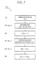
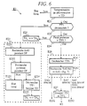
- an algorithm for responding to the terminal TA i to a temporary interruption originating from the switching center C comprises six main steps E1 to E6.
- the terminal TA i is initially in communication with the terminal TA k .
- the terminal TA i When the disappearance of the signal modulating the carrier frequency occurs, the terminal TA i does not know the event which caused it and seeks to identify this event.
- step E2 the terminal called TA i identifies the event which caused the disappearance of the signal modulating the carrier frequency and searches for the terminal alert signal SAT and the user alert signal SAU.
- the terminal TA k has previously transmitted to the terminal TA i the indication signifying that the terminal TA k accepts the loss of the signal transmitted by the terminal TA i for a duration greater than the maximum duration necessary for a temporary interruption. If this prerequisite is not fulfilled, the process is interrupted, the terminal TA i does not search for the terminal alert signal SAT nor the user alert signal SAU and the communication is re-established between the terminals TA i and TA k .
- the main step E2 comprises seven steps E21 to E27 detailed with reference to FIG. 6.
- the terminal TA i then goes to step E3 in which it transmits the acknowledgment message ACX to the switching center C.
- the terminal TA i configures the MDM modem to receive data according to predetermined bit rates and format, corresponding to those used by the switching center C to transmit the data message, then searches for the carrier frequency of the center switch C.
- the main step E5 is the reception of the data message MD.
- the main steps E4 and E5 respectively comprise three steps E41 to E43 and four steps E51 to E54, which are detailed with reference to FIG. 9.
- the main step E6 is the reestablishment of the initial data communication between the terminal TA i and the TA k terminal.
- the communication between the terminals TA i and TA k is established according to recommendation V23 of the CCITT.
- the terminal TA i transmits data at a speed of 75 bit / s and receives data at a speed of 1200 bit / s.
- the terminal TA i triggers in step E21 a disconnection time delay TD equal to 430 ms.
- the time delay TD is the maximum duration during which the data communication is interrupted without causing the definitive break of the data communication between the terminals TA i and TA k . If at the end of the TD disconnection timeout, the terminal TA i has not found the signal modulating the carrier frequency of the modem of the terminal TA k , the terminal TA i switches to the local state, that is to say say a state permanently disconnected from the network.
- the terminal TA i checks in the next step E22 if an intermediate time delay TT1, worth approximately 1000 ms, has been previously started and is running out.
- the intermediate delay TT1 is a maximum duration between two successive interruptions of a communication between the terminals TA i and TA k .
- the two interruptions are the interruptions INT1 and INT2 corresponding respectively to the transmission of a user alert signal SAU and of a terminal alert signal SAT (FIG. 4).
- the intermediate delay TT1 depends on the duration of the delay TC1.
- Step E23 comprises five sub-steps E231 to E235.
- Sub-step E231 is the conventional search for the user alert signal SAU proper, during a time delay DP1.
- the terminal TA i When the terminal TA i has detected the user alert signal SAU, this corresponds to the identification of the interruption INT1.
- the terminal TA i searches in sub-step E232 for the presence of the signal modulating the carrier frequency of the terminal TA k , signaling the end of the interruption INT1. If the terminal TA i does not detect the signal modulating the carrier frequency of the terminal TA k for a predetermined duration DP2 equal to approximately 20 ms, it proceeds to sub-step E233 at which the modem of the terminal TA i enters the state local.
- Sub-step E233 corresponds to the break in the communication caused by the terminal TA i , that is to say the release of the line LA i by the terminal TA i .
- the terminal TA i When the terminal TA i has detected the signal modulating the carrier frequency of the terminal TA k in sub-step E232, it proceeds to sub-step E234 at which the disconnection time delay TD is stopped and if the terminal TA i has detected the user alert signal SAU in sub-step E231, the time delay TT1, equal to 1000 ms, is triggered. The algorithm then proceeds to the sub-step E235 for resuming communication with the terminal TA k .
- step E22 if the time delay TT1 has been previously started (sub-step E234) and is running out, this means that the terminal TA i has received a user alert signal SAU previously during a communication interruption INT1, and that the communication interruption corresponding to the disappearance of the signal modulating the carrier frequency which has just been noted in step E1 is likely to correspond to an INT2 interruption caused to transmit a data message MD ( Figure 4).
- the algorithm then goes to step E24 to check whether the absence of a signal modulating the carrier frequency lasts for at least a minimum verification time TT2 of around 60 ms.
- Step E25 is analogous to substep E235.
- step E24 If in step E24 the loss of signal modulating carrier frequency of the terminal TA k lasts more than the time delay TT2 equal to 60 ms, the terminal alert signal SAT is sought in step E26 to identify the interruption INT2 .
- Step E26 comprises two sub-steps E261 and E262.
- the search for the INT2 interrupt is conditioned by the prior reception of the user alert signal SAU. In addition, the prior reception of the user alert signal SAU must have taken place within the delay TT1 to condition the passage to step E26.
- Step E26 includes simultaneous searches SAT terminal alert signal and a possible another SAU user alert signal. Indeed, the switching center C is likely to transmit multiple user alert signals SAU successively before signal transmission SAT terminal alert.
- sub-step E261 the algorithm triggers a TT6 timer having a duration of approximately 260 ms.
- the TT6 timer is a wait delay for the SAT terminal alert signal. If at the end of the time delay TT6, the terminal TA i has not detected the terminal alert signal SAT nor the user alert signal SAU, the algorithm proceeds to sub-step E232 to restore communication with the terminal TA k .
- Sub-step E262 is the search for the signal SAT terminal alert and alert signal to use SAU simultaneously.
- the terminal TA i searches for a pattern M1 represented in FIG. 7 and comprising first, second and third successive signals.
- the first signal is a silence having a duration predetermined TT3, for example at least 20 ms.
- TT3 duration silence is caused by the silence TC2 (figure 4).
- the silence of duration TT3 of pattern M1 can be confused with TT2 duration silence (step E24) which conditions the search for the SAT terminal alert signal.
- the second signal is the SAT terminal for a TT4 period depending on the TC3 transmission time of the SAT signal by the center switch C ( Figure 4).
- the third signal is a TT5 duration silence caused by the start of the T1 duration silence transmitted through the switching center C.
- the TT5 duration is equal to minimum about 20 ms.
- Each of the rests of duration TT3 and TT5 corresponds to a received signal level having a power lower than the lowest level of the signals exchanged between the terminals TA i and TA k when they are in communication, in the frequency band between 300 Hz and 3400 Hz, i.e. a power lower than the power of any normal data signal transmitted in the line LA i .
- step E26 If no SAT terminal alert signal and no SAU user alert signal have been detected at the end of the time delay TT6 in step E26, then the algorithm proceeds to sub-step E232 in the purpose of re-establishing communication with the terminal TA k .
- step E26 If a user alert signal SAU has been detected in step E26, then the algorithm proceeds to step E232 to detect the signal modulating the carrier frequency of the terminal TA k , then to step E234 to restart timer TT1.
- step E26 If a SAT terminal alert signal has been detected in step E26, then the algorithm goes to step E27 to stop the timing of TD disconnection and TT1 timer, then goes to step E3 previously described (FIG. 5).
- the terminals TA i and TA k are in communication according to the recommendation V23 of the CCITT, the terminal TA i being in reception at the speed of 75 bit / s and in transmission at the speed of 1200 bit / s, the algorithm is amended.
- SAT terminal alert signal detection (step E26) is not conditioned by detection prior to a user alert signal SAU and the associated triggering of timer TT1 (steps E22 and E23).
- step E1 the MDM modem of the terminal TA i interrupts the transmission of the data signal to the terminal TA k as soon as the MDM modem has detected the loss of the signal modulating the carrier frequency of the terminal TA k to avoid disturbing the reception of the SAT terminal alert signal in the event of an INT2 interruption.
- the terminal alert signal SAT is detected by the pattern M1 as previously exposed.
- the algorithm is modified.
- the terminal TA i comprises a circuit for detecting the user alert signal SAU which permanently searches for the signal SAU as soon as the communication between the terminals TA i and TA k is established.
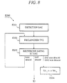
- the algorithm does not include the step E1 of terminal carrier frequency loss TA k and the main step E2 is replaced by the main step E200 described with reference to FIG. 8.
- the main step E200 includes four steps E201 to E204.
- Step E201 is the detection of the user alert signal SAU, after which the algorithm goes to step E202 to trigger a timer TV2, equal to approximately 1000 ms, during which a terminal alert signal SAT and a possible user alert signal SAU are sought simultaneously (step E203).
- the MDM modem of terminal TA i interrupts the transmission of the data signal to terminal TA k as soon as the detection circuit has detected the user alert signal to avoid disturbing the reception of the alert signal of terminal SAT in the case of the INT2 interrupt.
- the terminal alert signal SAT is detected by the pattern M1 as previously exposed.
- TV2 timer depends on the duration of timer TC1.
- step E203 If a user alert signal SAU is detected at step E203 then the algorithm returns to step E202 to restart the TV2 timer.
- step E203 If a SAT terminal alert signal is detected in step E203 then the algorithm goes to step E3 previously described.
- step E203 If no SAT terminal alert signal and no SAU user alert signal are detected in step E203 during the time delay TV2, the algorithm proceeds to step E204 to reestablish communication between the terminals TA i and TA k .
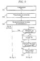
- the steps main E4 and E5 comprise three respectively substeps E41 to E43 and four substeps E51 to E54.
- Step E41 is the configuration of the terminal TA i to receive the data message MD from the switching center C according to a predetermined rate and format.
- the bit rate is 1200 bit / s and the format is 8 bits with no parity bit and with a stop bit.
- step E42 the algorithm triggers a TR search delay, approximately 380 ms, following the transmission of the message ACK acknowledgment.
- the TR delay limits the duration of step E43 of frequency search carrier typically at 1300 Hz and corresponding to "1" binary, transmitted by the switching center C. If at the end of the TR delay, the frequency carrier of switching center C was not detected, the algorithm goes to step E6.
- step E43 If in step E43 the carrier frequency of the center switch C is detected for an equal time at around 30 ms, then the algorithm goes to step E51 at which he waits to receive the first character of the MD data message.
- Step E51 avoids a blocking situation in case the switching center C interrupts the transmission of the data message MD unexpectedly. If the terminal TA i does not receive the first character of the data message MD during the time delay TR, then the algorithm proceeds to step E6.
- step E52 When the terminal TA i receives the first character of the message MD, the algorithm goes to step E52 to interrupt the time delay TR and then to step E53 to receive the data message MD.
- step E54 At the end of the reception of the data message MD, the algorithm searches in step E54 for a loss of the carrier frequency of the switching center C for a duration TT9 equal to approximately 40 ms. The algorithm then goes to step E6.
- the duration TT9 makes it possible to confirm the end of the transmission of data message MD before resuming the communication between the terminals TA i and TA k .
- the switching center transmits the data message MD to the terminal TA i in the form of a series of DTMF codes.
- the terminal TA i then comprises a receiver of DTMF codes for receiving the data message.
- the DTMF code receiver is permanently connected to the line or is connected after the transmission of the acknowledgment AC k .
- the terminal TA i detects the end of the data message MD by receiving a silence of duration greater than a predetermined duration corresponding to the maximum duration of silence between two successive DTMF codes. After the detection of silence, the terminal TA i re-establishes communication with the terminal TA k .
- the data message is an audio message received by a voice recognition circuit included in the terminal TA i .
- the terminals TA i and TA k use an error correction device.
- data exchanged between the terminals TA i and TA k which would be lost during the interruption of the communication, whatever the cause of this interruption, will be "repeated" after the resumption of the communication between the terminals TA i and TA k .
Landscapes
- Engineering & Computer Science (AREA)
- Signal Processing (AREA)
- Telephonic Communication Services (AREA)
Claims (11)
- Verfahren zur Unterbrechungssteuerung einer Verbindung, die über eine Analogverbindung zwischen ersten und zweiten Endgeräten (TAi, TAk) durch insbesondere ein von der Verbindung durchlaufenes Gerät, das die Unterbrechung (INT2) herbeiführt, wobei das Verfahren im ersten Endgerät (TAi) ausgeführt wird, dadurch gekennzeichnet, daß es den Schritt umfaßt, während einer vorbestimmten Suchzeitdauer (TT6, TV2) ein von dem Gerät (C) übertragenes Muster (M1) zu suchen (E26, E203) umfassend die Folge:wobei jedes der ersten und zweiten Ruhesignale eine Leistung kleiner als der geringste Leistungspegel der zwischen den ersten und zweiten Endgeräten ausgetauschten Signale im Frequenzband der ausgetauschten Signale aufweist.eines ersten Ruhesignals während einer ersten vorbestimmten Ruhezeitdauer (TT3),eines Endgerätalarmsignals (SAT), das durch das Gerät (C) übertragen wird,eines zweiten Ruhesignals während einer zweiten vorbestimmten Ruhezeitdauer (TT5),
- Verfahren zur Steuerung einer Unterbrechung nach Anspruch 1, gemäß dem das Gerät (C) die hergestellte Verbindung unterbricht, um ein Benutzeralarmsignal (SAU) vorhergehend zum Endgerätalarmsignal (SAT) zu übertragen,
dadurch gekennzeichnet, daß es die Schritte umfaßt:wobei der Schritt des Mustersuchens (E26) erst durchgeführt wird, nachdem der Verlust des die vorbestimmte Trägerfrequenz modulierenden Signals während der ausgelösten Zwischenverzögerungszeit (TT1) festgestellt worden ist.Feststellen (E1) der Unterbrechung der hergestellten Verbindung,Prüfen (E22) einer Auslösung einer Zwischenverzögerungszeit (TT1) folgend auf den vorhergehenden Feststellungsschritt,Suchen (E231) des durch das Gerät (C) übertragenen Benutzeralarmsignals (SAU) während einer vorbestimmten Zeitdauer (DP1), wenn die Zwischenverzögerungszeit (TT1) nicht ausgelöst ist,Suchen (E232) eines durch das zweite Endgerät während einer vorbestimmten Zeitdauer (DP2) übertragenen Signals, das eine vorbestimmte Trägerfrequenz moduliert, nachdem das gesuchte Benutzeralarmsignal (SAU) erfaßt worden ist,Auslösen (E234) der Zwischenverzögerungszeit (TT1), wenn das die vorbestimmte Trägerfrequenz modulierende Signal erfaßt worden ist, und Trennen (E233) der hergestellten Verbindung, wenn das gesuchte, die Trägerfrequenz modulierende Signal nicht erfaßt ist, - Verfahren zur Steuerung einer Unterbrechung nach Anspruch 1, dadurch gekennzeichnet, daß es vorhergehend zum Schritt (E203) des Mustersuchens die Schritte umfaßt:Empfangen (E201) eines Benutzeralarmsignals (SAU) undAuslösen (E202) einer Verzögerungszeit (TV2) entsprechend der vorbestimmten Suchzeitdauer.
- Verfahrung zur Steuerung einer Unterbrechung nach Anspruch 2, dadurch gekennzeichnet, daß es den Schritt (E21) umfaßt, daß vorhergehend zu den Schritten (E231, E26) des Suchens des Benutzeralarmsignals (SAU) und des Mustersuchens (M1) eine Abschältverzögerungszeit ausgelöst wird, wobei die Abschaltverzögerungszeit (TD) eine maximale Verlustzeitdauer des die vorbestimmte Trägerfrequenz modulierenden Signals ist, über die hinaus das erste Endgerät (TAi) die hergestellte Verbindung trennt, und daß am Ende der Abschaltverzögerungszeit das erste Endgerät (TAi) die Verbindung mit dem zweiten Endgerät (TAk) wiederherstellt, wenn das die vorbestimmte Trägerfrequenz modulierende Signal wiedergefunden wird und wenn weder ein Benutzeralarmsignal (SAU), noch irgendein Muster (M1) erfaßt worden ist (E264, E232, E235).
- Verfahren zur Unterbrechungssteuerung nach einem beliebigen der Ansprüche 1 bis 4, dadurch gekennzeichnet, daß es den Schritt (E3) umfaßt, daß ein Empfangsbestätigungssignal (ACK) durch das erste Endgerät (TAi) übertragen wird, wenn das Muster (M1) beim Schritt (E26) des Suchens des Musters (M1) erfaßt worden ist.
- Verfahren zur Unterbrechungssteuerung nach Anspruch 5, dadurch gekennzeichnet, daß es folgend auf den Schritt (E3) des Übertragens des Empfangsbestätigungssignals (ACK) die Schritte umfaßt:Suchen (E43) einer durch das Gerät (C) übertragenen vorbestimmten Trägerfrequenz,Empfangen (E53) einer durch das Gerät (C) übertragenen Datennachricht (MD), wenn die vorbestimmte Trägerfrequenz während einer vorbestimmten Zeitdauer (TR) gefunden wird,Suchen (E54) eines Verlusts der vorbestimmten Trägerfrequenz während einer vorbestimmten Zeitdauer (TT9), nachdem die Nachricht (MD) empfangen worden ist,Herstellen (E6) der unterbrochenen Verbindung zwischen den ersten und zweiten Endgeräten (TAi, TAk), sowie der Verlust der vorbestimmten Trägerfrequenz während der vorbestimmten Zeitdauer (TT9) beim vorgehenden Schritt erfaßt wird.
- Unterbrechungssteuerungsverfahren nach Anspruch 5, dadurch gekennzeichnet, daß es folgend auf den Schritt (E3) der Übertragung des Empfangsbestätigungssignals (ACK) die Schritte umfaßt:Empfangen einer Datennachricht in Form einer MFV-Codefolge,Erfassen einer Ruhezeitdauer größer als eine vorbestimmte Zeitdauer entsprechend der Zeitdauer zwischen zwei aufeinanderfolgenden MFV-Codes, undWiederherstellen der unterbrochenen Verbindung zwischen den ersten und zweiten Endgeräten, sobald die Ruhe beim vorgehenden Schritt erfaßt worden ist.
- Unterbrechungssteuerungsverfahren nach einem beliebigen der Ansprüche 1 bis 7, dadurch gekennzeichnet, daß das Endgerätalarmsignal (SAT) ein Sinussignal umfaßt, das eine Frequenz aufweist, die etwa im Frequenzband der zwischen den ersten und zweiten Endgeräten (TAi, TAK) ausgetauschten Signale enthalten ist.
- Verfahren, das in einem Gerät (C) ausgeführt wird, um vorübergehend eine zwischen ersten und zweiten Endgeräten (TAi, TAk) hergestellte und das Gerät durchlaufende Verbindung zu unterbrechen, wobei das erste Endgerät (TAi) das Verfahren zur Steuerung der Unterbrechung einer Verbindung nach einem beliebigen der Ansprüche 1 bis 8 ausführt,
wobei das Verfahren im Gerät die aufeinanderfolgenden Schritte umfaßt:dadurch gekennzeichnet, daß es den Schritt umfaßt:Unterbrechen (INT1) der zwischen den ersten und zweiten Endgeräten hergestellten Verbindung,Übertragen eines Benutzeralarmsignals (SAU) vom Gerät zum ersten Endgerät (TAi),Übertragen eines Endgerätalarmsignals (SAT) vom Gerät zum ersten Endgerät,Auslösen einer Warteverzögerungszeit (T1) eines Empfangsbestätigungssignals (ACK), das vom ersten Endgerät aus zum Gerät übertragen wird,Wiederherstellen der Verbindung zwischen den ersten und zweiten Endgeräten (TAi, TAk) nach der Warteverzögerungszeit (T1), wenn das Gerät (C) das Empfangsbestätigungssignal (ACK) nicht empfängt, oder nach dem Empfang des Empfangsbestätigungssignals (ACK) und der Übertragung einer Datennachricht (MD) vom Gerät zum ersten Endgerät,Wiederherstellen der Verbindung zwischen den ersten und zweiten Endgeräten (TAi, TAk) während einer vorbestimmten Zeitdauer (TC1) zwischen dem Schritt der Übertragung des Benutzeralarmsignals (SAU) und dem Schritt des Übertragens des Endgerätalarmsignals (SAT). - Verfahren nach Anspruch 9, dadurch gekennzeichnet, daß es den Schritt umfaßt:Übertragen eines Ruhesignals mit einer Leistung kleiner als eine vorbestimmte Leistung während erster und zweiter vorbestimmter Ruhezeitdauern (TC2, T1), jeweils vorhergehend und folgend auf den Schritt der Übertragung des Endgerätalarmsignals (SAT).
- Verfahren nach Anspruch 9 oder 10, dadurch gekennzeichnet, daß es den Schritt umfaßt:Übertragen eines Ruhesignals mit einer Leistung kleiner als eine vorbestimmte Leistung während einer dritten vorbestimmten Zeitdauer (TC7) folgend auf die Übertragung der Datennachricht (MD).
Applications Claiming Priority (4)
| Application Number | Priority Date | Filing Date | Title |
|---|---|---|---|
| FR9500980 | 1995-01-27 | ||
| FR9500980A FR2730114B1 (fr) | 1995-01-27 | 1995-01-27 | Interruption d'une communication entre deux terminaux par un appel d'un autre terminal |
| PCT/FR1996/000117 WO1996023382A1 (fr) | 1995-01-27 | 1996-01-24 | Interruption d'une communication entre deux terminaux par un appel d'un autre terminal |
| US08/898,321 US5930347A (en) | 1995-01-27 | 1997-07-22 | Interruption of a call between two terminals by a call from another terminal |
Publications (2)
| Publication Number | Publication Date |
|---|---|
| EP0806103A1 EP0806103A1 (de) | 1997-11-12 |
| EP0806103B1 true EP0806103B1 (de) | 2002-04-17 |
Family
ID=26231717
Family Applications (1)
| Application Number | Title | Priority Date | Filing Date |
|---|---|---|---|
| EP96901844A Expired - Lifetime EP0806103B1 (de) | 1995-01-27 | 1996-01-24 | Unterbrechung einer kommunikationsverbindung zwischen zwei endgeräten |
Country Status (5)
| Country | Link |
|---|---|
| US (1) | US5930347A (de) |
| EP (1) | EP0806103B1 (de) |
| CA (1) | CA2210709C (de) |
| FR (1) | FR2730114B1 (de) |
| WO (1) | WO1996023382A1 (de) |
Families Citing this family (7)
| Publication number | Priority date | Publication date | Assignee | Title |
|---|---|---|---|---|
| DE69634000T2 (de) * | 1995-08-31 | 2005-12-15 | Koninklijke Philips Electronics N.V. | Telekommunikationssystem und verfahren, um einem besetzten teilnehmer eine nachricht zu übermitteln |
| DE19736648C2 (de) * | 1997-08-22 | 1999-07-22 | Siemens Ag | Modem |
| US6067353A (en) * | 1998-12-03 | 2000-05-23 | Human Electronics, Inc. | Method and apparatus for detecting a call waiting signal on a telephone line connected to a modem |
| FR2791500B1 (fr) * | 1999-03-22 | 2001-07-06 | Cit Alcatel | Lien telephonique dynamique multivoie et procede de fonctionnement de ce lien |
| EP1454472B1 (de) * | 2001-12-13 | 2006-05-03 | Matsushita Electric Industrial Co., Ltd. | Kommunikationsgerät, empfangprozessausführungs- verfahren und -program, und rechnerlesbares medium auf dem dieses program gespeichert ist |
| WO2003096577A1 (en) * | 2002-05-10 | 2003-11-20 | Mitsubishi Denki Kabushiki Kaisha | Communication system, base station, and mobile station |
| CN101102304B (zh) * | 2006-08-18 | 2010-05-12 | 中兴通讯股份有限公司 | 一种控制音元间隔和脉冲间隔恢复通话的方法 |
Family Cites Families (10)
| Publication number | Priority date | Publication date | Assignee | Title |
|---|---|---|---|---|
| DE3315884A1 (de) * | 1983-05-02 | 1984-11-08 | Telefonbau Und Normalzeit Gmbh, 6000 Frankfurt | Verfahren und schaltungsanordnung zum betreiben einer zentralgesteuerten fernmelde-,insbesondere fernsprechvermittlungsanlage |
| US4852151A (en) * | 1988-02-24 | 1989-07-25 | Hayes Microcomputer Products, Inc. | Modem with call waiting |
| US5263084A (en) * | 1991-07-22 | 1993-11-16 | Northern Telecom Limited | Spontaneous caller identification with call-waiting |
| US5539812A (en) * | 1992-07-29 | 1996-07-23 | Kitchin; Dwight W. | Method and apparatus for detecting an attempted three-way conference call on a remote telephone |
| US5319702A (en) * | 1992-07-29 | 1994-06-07 | Tele-Matic Corporation | Method and apparatus for detecting and responding to hook flash events occurring on a remote telephone |
| US5450485A (en) * | 1993-03-08 | 1995-09-12 | Dialogic Corporation | Detecting whether a telephone line has been disconnected |
| US5287401A (en) * | 1993-03-15 | 1994-02-15 | Intel Corporation | Apparatus and method for a modem for detecting a call waiting signal |
| US5406621A (en) * | 1994-04-22 | 1995-04-11 | Binal; Mehmet E. | Telephone tone analysis system |
| US5651060A (en) * | 1994-11-15 | 1997-07-22 | Catapult Entertainment, Inc. | Method and apparatus for detecting and recovering from call waiting interruptions to modem communications |
| US5644634A (en) * | 1995-11-29 | 1997-07-01 | Advanced Micro Devices | System and method for dual tone multifrequency detection using variable frame widths |
-
1995
- 1995-01-27 FR FR9500980A patent/FR2730114B1/fr not_active Expired - Fee Related
-
1996
- 1996-01-24 CA CA002210709A patent/CA2210709C/en not_active Expired - Fee Related
- 1996-01-24 EP EP96901844A patent/EP0806103B1/de not_active Expired - Lifetime
- 1996-01-24 WO PCT/FR1996/000117 patent/WO1996023382A1/fr not_active Ceased
-
1997
- 1997-07-22 US US08/898,321 patent/US5930347A/en not_active Expired - Lifetime
Also Published As
| Publication number | Publication date |
|---|---|
| WO1996023382A1 (fr) | 1996-08-01 |
| CA2210709C (en) | 2000-07-18 |
| EP0806103A1 (de) | 1997-11-12 |
| FR2730114B1 (fr) | 1997-04-11 |
| FR2730114A1 (fr) | 1996-08-02 |
| US5930347A (en) | 1999-07-27 |
| CA2210709A1 (en) | 1996-08-01 |
Similar Documents
| Publication | Publication Date | Title |
|---|---|---|
| US6339639B1 (en) | Enhanced call-waiting with caller identification method and apparatus | |
| US6418198B2 (en) | Apparatus and method for verification of the presence of a remote user | |
| JPH10513632A (ja) | インターネットに接続された電話回線のための呼通知機能 | |
| WO1998028855A2 (en) | Multiple line modem and method for providing voice on demand | |
| EP0806103B1 (de) | Unterbrechung einer kommunikationsverbindung zwischen zwei endgeräten | |
| US6018577A (en) | Data messaging method | |
| JP3136311B2 (ja) | 電話ループ中で電話交換機が送信した顧客警告トーンを確認する方法 | |
| EP0608170A1 (de) | Bildfernsprech-Verfahren und -Endstation für das Abfangen und gegebenenfalls Anrufen von einem Fernsprechgerät | |
| US5835574A (en) | Dual-tone multi-frequency signal transfer protocol | |
| US6760368B1 (en) | Fast retraining method, apparatus, and storage medium in an xDSL transceiver | |
| EP0551950B1 (de) | Videotext- und Faksimilegerät | |
| FR2781968A1 (fr) | Procede d'etablissement d'une communication entre deux terminaux de transmission d'informations et terminal pour la mise en oeuvre du procede | |
| US6668059B1 (en) | Telephone tuning and signaling system | |
| US6640318B1 (en) | Continuity testing in communication networks | |
| US6697482B1 (en) | Method and system for transmitting messages to subscribers during the set-up stage of incoming telephone calls | |
| JP3505499B2 (ja) | 通報システム及びターミナルアダプタ | |
| JP3291413B2 (ja) | 電話端末用受信回路 | |
| FR2859861A1 (fr) | Procede, terminal et serveur de telephonie fixe permettant l'envoi et la reception de messages sms | |
| DE69620743T2 (de) | Unterbrechung einer kommunikationsverbindung zwischen zwei endgeräten | |
| JP2939678B2 (ja) | ファクシミリ信号監視装置 | |
| FR2500246A1 (fr) | Dispositif de selection d'appareil terminal raccordable au reseau commute | |
| FR2876237A1 (fr) | Procede et systeme de filtrage tarifaire pour appels telephoniques entrants | |
| EP1047254A1 (de) | Verbindungssystem zwischen einem analogen Endgerät und einer analogen Fernsprechanlage | |
| JPH0634494B2 (ja) | 着信転送方式 | |
| KR20010059638A (ko) | 전전자교환기에서 발신자 정보 제공방법 |
Legal Events
| Date | Code | Title | Description |
|---|---|---|---|
| PUAI | Public reference made under article 153(3) epc to a published international application that has entered the european phase |
Free format text: ORIGINAL CODE: 0009012 |
|
| 17P | Request for examination filed |
Effective date: 19970707 |
|
| AK | Designated contracting states |
Kind code of ref document: A1 Designated state(s): DE GB |
|
| GRAG | Despatch of communication of intention to grant |
Free format text: ORIGINAL CODE: EPIDOS AGRA |
|
| GRAG | Despatch of communication of intention to grant |
Free format text: ORIGINAL CODE: EPIDOS AGRA |
|
| GRAH | Despatch of communication of intention to grant a patent |
Free format text: ORIGINAL CODE: EPIDOS IGRA |
|
| 17Q | First examination report despatched |
Effective date: 20010719 |
|
| GRAH | Despatch of communication of intention to grant a patent |
Free format text: ORIGINAL CODE: EPIDOS IGRA |
|
| REG | Reference to a national code |
Ref country code: GB Ref legal event code: IF02 |
|
| GRAA | (expected) grant |
Free format text: ORIGINAL CODE: 0009210 |
|
| AK | Designated contracting states |
Kind code of ref document: B1 Designated state(s): DE GB |
|
| REF | Corresponds to: |
Ref document number: 69620743 Country of ref document: DE Date of ref document: 20020523 |
|
| GBT | Gb: translation of ep patent filed (gb section 77(6)(a)/1977) |
Effective date: 20020710 |
|
| PLBE | No opposition filed within time limit |
Free format text: ORIGINAL CODE: 0009261 |
|
| STAA | Information on the status of an ep patent application or granted ep patent |
Free format text: STATUS: NO OPPOSITION FILED WITHIN TIME LIMIT |
|
| 26N | No opposition filed |
Effective date: 20030120 |
|
| PGFP | Annual fee paid to national office [announced via postgrant information from national office to epo] |
Ref country code: DE Payment date: 20061227 Year of fee payment: 12 |
|
| PGFP | Annual fee paid to national office [announced via postgrant information from national office to epo] |
Ref country code: GB Payment date: 20061228 Year of fee payment: 12 |
|
| GBPC | Gb: european patent ceased through non-payment of renewal fee |
Effective date: 20080124 |
|
| PG25 | Lapsed in a contracting state [announced via postgrant information from national office to epo] |
Ref country code: DE Free format text: LAPSE BECAUSE OF NON-PAYMENT OF DUE FEES Effective date: 20080801 |
|
| PG25 | Lapsed in a contracting state [announced via postgrant information from national office to epo] |
Ref country code: GB Free format text: LAPSE BECAUSE OF NON-PAYMENT OF DUE FEES Effective date: 20080124 |