EP0806091B1 - Übertragungssystem für ein nichtlineares übertragungsmedium - Google Patents
Übertragungssystem für ein nichtlineares übertragungsmedium Download PDFInfo
- Publication number
- EP0806091B1 EP0806091B1 EP96935291A EP96935291A EP0806091B1 EP 0806091 B1 EP0806091 B1 EP 0806091B1 EP 96935291 A EP96935291 A EP 96935291A EP 96935291 A EP96935291 A EP 96935291A EP 0806091 B1 EP0806091 B1 EP 0806091B1
- Authority
- EP
- European Patent Office
- Prior art keywords
- deriving
- coded
- amplitude
- digital symbols
- signal
- Prior art date
- Legal status (The legal status is an assumption and is not a legal conclusion. Google has not performed a legal analysis and makes no representation as to the accuracy of the status listed.)
- Expired - Lifetime
Links
- 230000005540 biological transmission Effects 0.000 title claims abstract description 64
- 230000003287 optical effect Effects 0.000 claims description 13
- 230000007423 decrease Effects 0.000 description 7
- 239000000969 carrier Substances 0.000 description 4
- 239000000835 fiber Substances 0.000 description 4
- 230000003247 decreasing effect Effects 0.000 description 3
- 238000013139 quantization Methods 0.000 description 3
- 230000006870 function Effects 0.000 description 2
- 239000013307 optical fiber Substances 0.000 description 2
- 230000004044 response Effects 0.000 description 2
- 238000004364 calculation method Methods 0.000 description 1
- 238000000034 method Methods 0.000 description 1
- 230000005693 optoelectronics Effects 0.000 description 1
Images
Classifications
-
- H—ELECTRICITY
- H04—ELECTRIC COMMUNICATION TECHNIQUE
- H04L—TRANSMISSION OF DIGITAL INFORMATION, e.g. TELEGRAPHIC COMMUNICATION
- H04L27/00—Modulated-carrier systems
- H04L27/32—Carrier systems characterised by combinations of two or more of the types covered by groups H04L27/02, H04L27/10, H04L27/18 or H04L27/26
- H04L27/34—Amplitude- and phase-modulated carrier systems, e.g. quadrature-amplitude modulated carrier systems
- H04L27/36—Modulator circuits; Transmitter circuits
-
- H—ELECTRICITY
- H04—ELECTRIC COMMUNICATION TECHNIQUE
- H04L—TRANSMISSION OF DIGITAL INFORMATION, e.g. TELEGRAPHIC COMMUNICATION
- H04L25/00—Baseband systems
- H04L25/38—Synchronous or start-stop systems, e.g. for Baudot code
- H04L25/40—Transmitting circuits; Receiving circuits
- H04L25/49—Transmitting circuits; Receiving circuits using code conversion at the transmitter; using predistortion; using insertion of idle bits for obtaining a desired frequency spectrum; using three or more amplitude levels ; Baseband coding techniques specific to data transmission systems
- H04L25/4902—Pulse width modulation; Pulse position modulation
-
- H—ELECTRICITY
- H04—ELECTRIC COMMUNICATION TECHNIQUE
- H04L—TRANSMISSION OF DIGITAL INFORMATION, e.g. TELEGRAPHIC COMMUNICATION
- H04L25/00—Baseband systems
- H04L25/38—Synchronous or start-stop systems, e.g. for Baudot code
- H04L25/40—Transmitting circuits; Receiving circuits
- H04L25/49—Transmitting circuits; Receiving circuits using code conversion at the transmitter; using predistortion; using insertion of idle bits for obtaining a desired frequency spectrum; using three or more amplitude levels ; Baseband coding techniques specific to data transmission systems
- H04L25/4906—Transmitting circuits; Receiving circuits using code conversion at the transmitter; using predistortion; using insertion of idle bits for obtaining a desired frequency spectrum; using three or more amplitude levels ; Baseband coding techniques specific to data transmission systems using binary codes
- H04L25/4908—Transmitting circuits; Receiving circuits using code conversion at the transmitter; using predistortion; using insertion of idle bits for obtaining a desired frequency spectrum; using three or more amplitude levels ; Baseband coding techniques specific to data transmission systems using binary codes using mBnB codes
-
- H—ELECTRICITY
- H04—ELECTRIC COMMUNICATION TECHNIQUE
- H04L—TRANSMISSION OF DIGITAL INFORMATION, e.g. TELEGRAPHIC COMMUNICATION
- H04L27/00—Modulated-carrier systems
- H04L27/02—Amplitude-modulated carrier systems, e.g. using on-off keying; Single sideband or vestigial sideband modulation
- H04L27/04—Modulator circuits; Transmitter circuits
-
- H—ELECTRICITY
- H04—ELECTRIC COMMUNICATION TECHNIQUE
- H04L—TRANSMISSION OF DIGITAL INFORMATION, e.g. TELEGRAPHIC COMMUNICATION
- H04L5/00—Arrangements affording multiple use of the transmission path
- H04L5/02—Channels characterised by the type of signal
- H04L5/06—Channels characterised by the type of signal the signals being represented by different frequencies
Definitions
- the present invention is related to a transmission system with a transmitter comprising coding means for deriving from a plurality of sequences of digital symbols a plurality of sequences of coded digital symbols and modulation means for deriving from said plurality of sequences of coded digital symbols a plurality of digitally modulated carrier signals, the transmitter further comprises combining means for deriving a combined signal from said plurality of digitally modulated carrier signals, the transmitter further being arranged for transmitting said combined signal over a non-linear transmission medium to a receiver, the receiver comprises demodulation means for deriving at least one sequence of coded symbols from the received signal and decoding means for deriving a sequence of digital symbols from said sequence of digital symbols.
- the present invention is also related to a transmitter, a coder/modulator, a receiver and a carrier signal for use in such a system.
- a combination of coding means and modulation means is known from US 5,062,152, that discloses a method for processing a pulse code modulated signal having a non-uniform probability density.
- the signal is quantized and the quantized signal is then coded using a non-sequential coding scheme in which binary codewords for the quantization levels are chosen in accordance with the probability of the quantization levels and number of ON bits in the codeword. Quantization levels of higher probability are assigned codewords with fewer ON bits to achieve minimum power codeword assignment.
- Such transmission systems according to the preamble can find their application in all kinds of transmission networks having a non-linear transmission medium.
- a first example of such a transmission system is an optical transmission system.
- the transmission system is here regarded to comprise an electro-optical convener, e.g. a laser, an optical transmission path such as an optical fiber or free space and an opto electrical converter such as a photo diode.
- an electro-optical convener e.g. a laser
- an optical transmission path such as an optical fiber or free space
- an opto electrical converter such as a photo diode.
- the non-linearity of the transmission system is mainly caused by the electro-optical converter, but is it also possible that substantial non-linearity is caused by optical amplifiers present in the transmission path.
- a second example of such a transmission system is a cable transmission network such as a CATV network.
- the non-linearity is mainly caused by the non-linearity of the amplifiers used at several places in the network.
- each of said sequences of digital symbols represents e.g. a separate (HD)TV program or a data service.
- each of said sequence is coded to obtain a sequence of coded digital symbols. Consequently the sequence of coded digital symbols is modulated on a proper carrier to obtain a modulated carrier signal.
- the different carrier signals are combined to a combined signal which is transmitted via the transmission medium.
- at least one of the modulated carrier signals is selected, demodulated and decoded to obtain the desired sequence of digital symbols.
- the combined signal will undergo some non-linear distortion, resulting in the generation of harmonics and intermodulation products.
- the presence of such distortion products will cause some interference to the desired signals leading to an increased error probability.
- the sequences of digital symbols are coded using a (255,239) BCH error correcting code to reduce the error probability of the received digital symbols. Due to the use of such error correcting code more distortion can be tolerated, and consequently larger signal amplitudes of the combined signal can be tolerated. This leads to an increased capacity of the transmission system. However the desire to increase the capacity of the transmission system even more still exists.
- the object of the present invention is to provide a transmission system according to the preamble having an increased capacity.
- the transmission system is characterized in that the coding means are arranged for deriving the plurality of sequences of coded digital symbols such that the larger the probability of a coded symbol is, the lower is the amplitude of the modulated signals corresponding to said coded symbol, a value of a modulation index of the combined signal leading to a maximum value of an amplitude to noise ratio of the combined signal.
- the present invention is based on the recognition that transmission of symbols corresponding to a modulated carrier signal with a large amplitude causes most of the non-linear distortion. By reducing the probability of said symbols, the average distortion introduced by all the carriers will decrease, and consequently the error probability will decrease too. This allows the use of still larger amplitudes. Thereby should a value of a modulation index of the combined signal lead to a maximum value of an amplitude to noise ratio of the combined signal, which leads to a maximum value of the channel capacity. By using a channel code in which the probability of symbols decreases with an increasing amplitude of the modulated carrier signal associated with it, the average signal amplitude is decreased.
- a first embodiment of the invention is characterized in that the non-linear transmission medium comprises a cascade connection of an electrical optical converter, an optical transmission channel and an opto-electrical converter.
- the non-linearity is mainly caused by clipping of the negative signal excursions of the combined signal due to a limited bias current of the laser diode.
- the non-linear distortion is therefore often called "clipping noise”.
- clipping noise it is also possible that some saturation occurs at the positive excursionsof the combined signal.
- a second embodiment of the invention is characterised in that the non-linear transmission medium comprises a plurality of channel sections being interconnected via at least one amplifier.
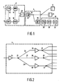
- a plurality of sequences of digital symbols are applied to inputs of the coding means being here coders 12 ⁇ 16.
- An output of each of the coders 12 ⁇ 16 is connected to an input of the modulation means, being here modulators 14 ⁇ 18.
- the outputs of the modulators 14 ⁇ 18 are connected to an input of the combining means 20.
- An output of the combining means 20 is connected to the input of the transmission medium.
- the input of the transmission medium is constituted by an input of an electro-optical converter 22.
- the output of the electro-optical converter 22 is connected to an input of a fibre network 24.
- a plurality of outputs of the fibre network 24 are connected to an input of opto-electric converters.
- One of these converters is explicitly drawn with reference no. 26.
- the outputs of the transmission medium 4 are constituted by the outputs of the opto-electrical converters.
- the input is connected to a selector 28.
- the output of the selector 28 is connected to an input of a demodulator 30.
- the output of the demodulator 30 is connected to an input of the decoder 32.
- the decoder 32 At the output of the decoder 32 the reconstructed sequence of digital symbols is available.
- N sequences of digital symbols are converted into N sequences of coded digital symbols by the coders 12 ⁇ 16.
- Each of the sequences of digital symbols can represent an audio, video or data signal.
- a digitally modulated carrier signal is obtained by modulating a carrier signal at least in amplitude.
- Suitable modulation schemes are e.g. ASK (Amplitude Shift Keying) and QAM (Quadrature Amplitude Modulation).
- the modulated carrier signals are combined in an adder 20.
- the output of the adder 20, carrying the combined signal is connected to the non-linear transmission medium.
- the non-linearity is caused by the laser 22 mainly due to the negative excursions of the combined signal. If the bias current of the laser 22 is equal to I b , the amplitude I c of the current representing the combined signal should be smaller than I b for distortion free transmission.
- the modulation index m I c /I b should be consequently smaller than 1. If the combined signal comprises N modulated carriers the modulation index m i of each modulated carrier signal is limited to 1/N (if m i is equal for all carriers) for distortion free transmission.
- a i,j is the normalised amplitude of the modulated i th carrier corresponding to the j th symbol.
- the output signal of the laser 22 is distributed via the fibre network 24 to a plurality of sub-stations 6, ..., 8 and 10.
- the output signal of the transmission medium 4 is available at the output of the opto-electrical converter 26.
- the selector 28 selects one of the modulated carrier signals for demodulation.
- the selector 28 can comprise a tunable bandfilter, but it is also possible that the selection is made by converting the input signal to a lower IF frequency by mixing it with a local oscillator signal with adjustable frequency.
- the opto-electrical converter 26 generates an electric signal which essentially proportional to the power of the received optical signal.
- the non linear distortion of the transmission network generates harmonic components and intermodulation products.
- the noise like signal caused by the non linear transmission medium three other noise components are present at the input of the receiver.
- a first one is the so called Relative Intensity Noise (RIN) which is generated in the electro-optical converter, and which has a constant level at the output of the electro-optical converter.
- RIN Relative Intensity Noise
- a second and a third noise component is the noise of the electrical-optical converter and the noise caused by the electronic circuitry.
- the noise of the opto-electronic converter is proportional to the received optical signal, and the noise of the electronic circuitry is under normal circumstances constant.
- ANR A N RIN + N SHOT + N REC + N CLIP
- A is the amplitude of the modulated carrier signal
- N RIN is the relative intensity noise
- N SHOT is the shot noise of the opto-electrical converter
- N REC is the receiver noise
- N CLIP is the clipping noise due to the non-linear transmission medium.
- N RIN , N SHOT and N REC are independent of the modulation index m i .
- A increases proportional with m i and N CLIP increases more than proportional with m i . In this situation there is a value of m i leading to a maximum value of ANR, and consequently to a maximum value of the channel capacity.
- the modulated carrier signal available at the output of the selector 28 is demodulated by the demodulator 30.
- the signal at the output of the demodulator 30 is the demodulated sequence of coded digital symbols. This sequence is decoded by the decoder 32. At the output of the decoder 32 the sequence of digital symbols is available.
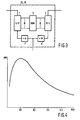
- the input is connected to an input of a amplifier 34.
- the output of the amplifier 34 is connected to an input of a power splitter 35.
- a first output of the power splitter 35 is connected to an input of an amplifier 36 via a cable section 25.
- a second output of the power splitter 35 is connected to an input of an amplifier 38 via a cable section 27.
- a third output of the power splitter 35 is connected to an input of an amplifier 40 via a cable section 29.
- the output of the amplifier 36 is connected to an input of a power splitter 37. Three outputs of the power splitter 37 are connected to drop sections for the secondary stations.
- the output of the amplifier 38 is connected to an input of a power splitter 39. Two outputs of the power splitter 39 are connected to drop section for the secondary stations.
- the output of the amplifier 40 is connected to the input of a power splitter 41. Three outputs of the power splitter 41 are connected to drop sections for the subscribers.
- a non linear transmission medium according to Fig. 2 can e.g. be found in CATV systems.
- the non linearity is caused by the amplifiers 34, 36, 38 and 40.
- the gain of the amplifier 34 has been chosen to compensate the attenuation due to the splitting by the power splitter 35 and the loss in the cable sections 25, 27 and 29.
- the gain of the amplifiers 36, 38 and 40 has been chosen to compensate the attenuation due to the splitting by the power splitters 37, 39 and 41 respectively and the loss in the corresponding drop section.
- the input of the coder 12 ⁇ 16 according to Fig. 3 is connected to an input of a series to parallel converter 1.
- M outputs of the series to parallel converter 1 are connected to M inputs of a read only memory 3.
- N outputs of the read only memory 3 are connected to a parallel to series converter 5.
- the output of the parallel to series converter 5 constitutes the output of the coder 12 ... 16.
- a clock input of the coder 12 ... 16 is connected to an input of a frequency divider 7 with a division factor N, and to an input of frequency divider 9 with a division factor M.
- the output of the frequency divider 7 is connected to a clock input of the series to parallel converter 1.
- the output of the frequency divider 9 is connected to a clock input of the parallel to series converter 5.
- the coder 12 ... 16 In case binary amplitude shift keying is used, the coder 12 ... 16 generates in response to a sequence of binary symbols having P(1) and P(0) equal to 0.5 a sequence of binary symbols having P(1) ⁇ 0.5 and having P(0) > 0.5.
- R source is the symbol rate of the source
- H CC is the entropy of the channel code.
- H CC - P 1 ⁇ logP 1 2 - P 0 ⁇ logP 0 2
- the ratio between the channel rate R CH and the source rate R source is equal to N/M.
- the output signal of the frequency divider 7 has a frequency f r /N and the output signal of the frequency divider 9 has a frequency of f r /M.
- M source symbols are clocked into the series parallel converted during a period of M ⁇ N/f r . These symbols are subsequently applied to the ROM 3.
- the ROM 3 provides N coded symbols in response to the M input symbols. These coded symbols are transferred to the parallel-series converter 5. The coded symbols are converted in a serial stream with symbol rate f r /M by clocking the series-parallel converter 4 with the clock signal with frequency f r /M provided by the frequency divider 9. Consequently in the period N ⁇ M/f r N symbols are serially transmitted by the coder.
- a first useful code which converts 3 input bits a i into 8 output bits b j : a 2 a 1 a 0 b 7 b 6 b 5 b 4 b 3 b 2 b 1 b 0 0 0 0 1 0 0 0 0 0 0 0 0 0 1 0 1 0 0 0 0 0 0 0 1 0 0 0 0 0 0 0 1 1 0 0 0 0 0 0 0 0 1 1 0 0 0 0 1 0 0 0 0 1 0 0 0 0 0 1 0 0 0 0 0 0 1 0 1 0 0 0 0 0 0 1 0 1 0 0 0 0 0 0 1 0 1 0 0 0 0 0 0 1 0 1 0 0 0 0 0 0 1 0 1 0 0 0 0
- the probability of symbol value 1 is equal to 1/8. If the logical value of "1" corresponds to the amplitude value of the modulated carrier signal being higher than the amplitude value corresponding to logical value "0", this results in a decrease of the average power of the modulated carrier signal.
- a further code which can be used with the present invention is given in the table below: a 2 a 1 a 0 b 3 b 2 b 1 b 0 0 0 0 0 0 0 0 0 0 1 0 0 0 1 0 1 0 0 0 0 1 0 1 0 0 0 1 0 0 0 1 0 0 0 1 0 0 0 1 0 1 0 1 0 1 0 0 1 0 1 0 1 0 0 1 0 1 1 0 0 1 1 3 bits a i are converted into 4 bits b j .
- the rate of the coded symbols is 4/3 times the rate of the uncoded symbols.
- the probability of symbol value 1 is equal to 5/16.
- Fig. 4 shows the amplitude to noise ratio as a function of the probability of logical value "1". It is assumed that ASK modulation of the carrier is used. Further it is assumed that these are 64 carriers modulated with 2 Mbit/sec streams. It is further assumed that the output power of the electro-optical converter is 0 dBm and the attenuation (including splitting loss) of the fiber network is 34.4 dB. It is also assumed that the RIN can be neglected, m i is equal to 0.4 and that the value of the noise current I n 2 at the output of the opto-electrical converter is equal to 4 pA 2 /Hz.
- the receiver noise dominates.
- the amplitude to noise ratio decreases with P(1) due to the increased bandwidth required.
- the ANR decreases due to the rapidly increasing value of the noise like signal caused by distortion by the non-linear transmission medium
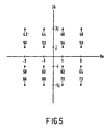
- Fig. 5 shows the constellation of a QAM signal to be used with the invention, In this case a kind of coded modulation is used. 4 subsequent bits are mapped on two subsequent symbols according to the constellation of Fig. 4.
- a 3 A 2 A 1 A 0 C 1 C 2 0 0 0 0 42 44 0 0 0 1 50 52 0 0 1 0 58 66 0 0 1 1 60 68 0 1 0 0 62 64 0 1 0 1 70 72 0 1 1 0 46 54 0 1 1 1 48 56 1 0 0 0 0 52 54 1 0 0 1 52 62 1 0 1 0 52 60 1 0 1 1 54 62 1 1 0 0 54 60 1 1 0 1 62 60 1 1 1 1 0 54 56 1 1 1 1 58 60 The rate of the code according to the above mentioned table is 0.5.
- the symbols C j can have the amplitude values a ⁇ 2, a ⁇ 10 and 3a ⁇ 2, a being a constant.
- the probability of an amplitude value of 3a ⁇ 2 1/8.
Landscapes
- Engineering & Computer Science (AREA)
- Signal Processing (AREA)
- Computer Networks & Wireless Communication (AREA)
- Physics & Mathematics (AREA)
- Spectroscopy & Molecular Physics (AREA)
- Optical Communication System (AREA)
- Digital Transmission Methods That Use Modulated Carrier Waves (AREA)
- Reduction Or Emphasis Of Bandwidth Of Signals (AREA)
Claims (7)
- Übertragungssystem mit einem Sender (2) mit Codierungsmitteln (12, 16) zum Herleiten einer Anzahl Sequenzen codierter digitaler Symbole aus einer Anzahl Sequenzen digitaler Symbole, und mit Modulationsmitteln (14, 18) zum herleiten einer Anzahl digital modulierter Trägersignale aus der genannten Anzahl Sequenzen codierter digitaler Symbole, wobei der Sender (2) weiterhin Kombinationsmittel (20) aufweist zum Herleiten eines kombinierten Signals aus der genannten Anzahl digital modulierter Trägersignale, wobei der Sender (2) weiterhin dazu vorgesehen ist, das genannte kombinierte Signal über ein nicht lineares Übertragungsmittel (4) zu einem Empfänger (10) zu übertragen, wobei der Empfänger (10) Demodulationsmittel (30) aufweist zum Herleiten wenigstens einer Sequenz codierter Symbole aus dem empfangenen Signal und Decodierungsmittel (32) zum herleiten einer Sequenz digitaler Symbole aus der genannten Sequenz digitaler Symbole, dadurch gekennzeichnet, dass die Codierungsmittel (12, 16) vorgesehen sind zum Herleiten von Sequenzen codierter digitaler Symbole, so dass je größer die Wahrscheinlichkeit eines codierten Symbols ist, umso kleiner ist die Amplitude der modulierten Signale, die dem genannten codierten Symbol entsprechen und dadurch, dass ein Wert eines Modulationsindexes des kombinierten Signals derart gewählt wird, das dies zu einem maximalen Wert eines Amplitude-Rausch-Verhältnisses des kombinierten Signals führt.
- Übertragungssystem nach Anspruch 1, dadurch gekennzeichnet, dass das nicht lineare Übertragungsmedium (4) eine Kaskadenschaltung eines elektrisch-optischen Wandlers (22), eines optischen Übertragungskanals (24) und eines optisch-elektrischen Wandlers (26) aufweist.
- Übertragungssystem nach Anspruch 1, dadurch gekennzeichnet, dass das nicht lineare Übertragungsmedium eine Anzahl Kanalabschnitte (25, 27, 29) aufweist, die über wenigstens einen Verstärker (34) miteinander verbunden sind.
- Sender (2) mit Codierungsmitteln (12, 16) zum Herleiten einer Anzahl Sequenzen codierter digitaler Symbole aus einer Anzahl Sequenzen digitaler Symbole, und mit Modulationsmitteln (14, 18) zum Herleiten einer Anzahl digital modulierter Trägersignale aus der genannten Anzahl Sequenzen codierter digitaler Symbole, wobei der Sender (2) weiterhin Kombiniermittel (20) aufweist zum Herleiten eines kombinierten Signals aus der genannten Anzahl digital modulierter Trägersignale, dadurch gekennzeichnet, dass die Codierungsmittel (12, 16) vorgesehen sind zum Herleiten von Sequenzen codierter digitaler Symbole, so dass je größer die Wahrscheinlichkeit eines codierten Symbols ist, umso niedriger ist die Amplitude der modulierten Signale entsprechend dem genannten codierten Symbol, und dadurch, dass ein Wert eines Modulationsindexes des kombinierten Signals derart gewählt wird, dass dies zu einem maximalen Wert eines Amplitude-Rauschverhältnisses des kombinierten Signals führt.
- Codierer/Modulator mit Codierungsmitteln (12, 16) zum Herleiten einer Sequenz codierter digitaler Symbole aus einer Sequenz digitaler Symbole und mit Modulationsmitteln (14, 18) zum herleiten eines digital modulierten Trägersignals aus der genannten Sequenz codierter digitaler Symbole, dadurch gekennzeichnet, dass die Codierungsmittel (12, 16) vorgesehen sind zum Herleiten von Sequenzen codierter digitaler Symbole, so dass je größer die Wahrscheinlichkeit eines codierten Signals ist, umso niedriger die Amplitude der modulierten Signal ist, entsprechend dem codierten Symbol, und dadurch, dass ein Wert eines Modulationsindexes eines kombinierten Signals, hergeleitet von einer Anzahl digital modulierter Trägersignale, derart gewählt wird, dass dies zu einem maximalen Wert eines Amplitude-Rauschverhältnisses des kombinierten Signals führt.
- Empfänger (10) zum Empfangen wenigstens eines Signals mit einem digital modulierten Träger, wobei der genannte Empfänger (10) Demodulationsmittel (30) aufweist zum Herleiten wenigstens einer Sequenz codierter Symbole aus dem empfangenen Signal und mit decodiermittel (32) zum Herleiten einer Sequenz digitaler Symbole aus der genannten Sequenz codierter Symbole, dadurch gekennzeichnet, dass die Decodiermittel (32) vorgesehen sind zum Herleiten von Sequenzen digitaler Symbole, so dass je größer die Wahrscheinlichkeit eines codierten Symbols ist, umso niedriger die Amplitude der modulierten Signale ist, entsprechend dem genannten codierten Symbol, und dadurch, dass ein Wert eines Modulationsindexes eines kombinierten Signals, hergeleitet von einer Anzahl digital modulierter Trägersignale, derart gewählt wird, dass dies zu einem maximalen Wert eines Amplitude-Rauschverhältnisses des kombinierten Signals führt.
- Trägersignal, das wenigstens in der Amplitude moduliert ist mit einer Sequenz digitaler Symbole, dadurch gekennzeichnet, dass je größer die Wahrscheinlichkeit eines codierten Symbols ist, umso niedriger die Amplitude der modulierten Signale ist, entsprechend dem genannten codierten Symbol, und dadurch, dass ein Wert eines Modulationsindexes eines kombinierten Signals, hergeleitet von einer Anzahl digital modulierter Trägersignale, derart gewählt wird, dass dies zu einem maximalen Wert eines Amplitude-Rauschverhältnisses des kombinierten Signals führt.
Priority Applications (1)
| Application Number | Priority Date | Filing Date | Title |
|---|---|---|---|
| EP96935291A EP0806091B1 (de) | 1995-11-29 | 1996-11-20 | Übertragungssystem für ein nichtlineares übertragungsmedium |
Applications Claiming Priority (4)
| Application Number | Priority Date | Filing Date | Title |
|---|---|---|---|
| EP95203288 | 1995-11-29 | ||
| EP95203288 | 1995-11-29 | ||
| EP96935291A EP0806091B1 (de) | 1995-11-29 | 1996-11-20 | Übertragungssystem für ein nichtlineares übertragungsmedium |
| PCT/IB1996/001260 WO1997020399A1 (en) | 1995-11-29 | 1996-11-20 | Transmission system for a non linear transmission medium |
Publications (2)
| Publication Number | Publication Date |
|---|---|
| EP0806091A1 EP0806091A1 (de) | 1997-11-12 |
| EP0806091B1 true EP0806091B1 (de) | 2007-03-21 |
Family
ID=8220887
Family Applications (1)
| Application Number | Title | Priority Date | Filing Date |
|---|---|---|---|
| EP96935291A Expired - Lifetime EP0806091B1 (de) | 1995-11-29 | 1996-11-20 | Übertragungssystem für ein nichtlineares übertragungsmedium |
Country Status (6)
| Country | Link |
|---|---|
| US (1) | US5917858A (de) |
| EP (1) | EP0806091B1 (de) |
| JP (1) | JP3805372B2 (de) |
| CN (1) | CN1155163C (de) |
| DE (1) | DE69636981T2 (de) |
| WO (1) | WO1997020399A1 (de) |
Cited By (1)
| Publication number | Priority date | Publication date | Assignee | Title |
|---|---|---|---|---|
| WO2025221410A1 (en) * | 2024-04-19 | 2025-10-23 | Qualcomm Incorporated | Power control for non-uniform message transmissions |
Families Citing this family (5)
| Publication number | Priority date | Publication date | Assignee | Title |
|---|---|---|---|---|
| DE19713952C1 (de) * | 1997-04-04 | 1998-10-15 | Siemens Ag | Verfahren zur Übertragung von Zusatzdatensignalen und einem Nutzdatensignal über optische Verbindungen |
| US6030364A (en) * | 1997-10-03 | 2000-02-29 | Boston Scientific Corporation | Apparatus and method for percutaneous placement of gastro-intestinal tubes |
| JP4288777B2 (ja) * | 1999-08-11 | 2009-07-01 | ソニー株式会社 | マルチキャリア信号送信装置及びマルチキャリア信号受信装置 |
| US7068946B2 (en) | 2001-01-23 | 2006-06-27 | At&T Corp. | Modulation scheme for tedons |
| JP5940966B2 (ja) * | 2012-11-28 | 2016-06-29 | 日本電信電話株式会社 | 光伝送システム、光送信器、光受信器、光送信方法、光受信方法 |
Family Cites Families (9)
| Publication number | Priority date | Publication date | Assignee | Title |
|---|---|---|---|---|
| JPS61198935A (ja) * | 1985-02-28 | 1986-09-03 | Toshiba Corp | 光伝送方式 |
| GB8717124D0 (en) * | 1987-07-20 | 1987-08-26 | British Telecomm | P c m signal coding |
| US4942467A (en) * | 1988-12-05 | 1990-07-17 | General Electric Company | Predictor controlled encoder for digital transmission systems |
| DE3943880B4 (de) * | 1989-04-17 | 2008-07-17 | Fraunhofer-Gesellschaft zur Förderung der angewandten Forschung e.V. | Digitales Codierverfahren |
| IT1259012B (it) * | 1992-07-27 | 1996-03-11 | Alcatel Italia | Metodo e circuiti per la riduzione della potenza di picco del segnale filtrato trasmesso in un collegamento di tipo numerico |
| US5587830A (en) * | 1993-05-28 | 1996-12-24 | Lucent Technologies Inc. | High capacity optical fiber network |
| US5600473A (en) * | 1993-06-04 | 1997-02-04 | Ciena Corporation | Optical amplifier systems with add/drop multiplexing |
| US5541964A (en) * | 1993-08-30 | 1996-07-30 | At&T Corp. | Distortion compensation technique |
| IT1273695B (it) * | 1994-07-28 | 1997-07-09 | Alcatel Italia | Metodo e circuiti per la trasmissione e la ricezione di segnali numerici nel quale si riduce la potenza di picco del segnale filtrato trasmesso compatibili con tecniche di codifica note |
-
1996
- 1996-11-20 EP EP96935291A patent/EP0806091B1/de not_active Expired - Lifetime
- 1996-11-20 DE DE69636981T patent/DE69636981T2/de not_active Expired - Lifetime
- 1996-11-20 CN CNB961916397A patent/CN1155163C/zh not_active Expired - Fee Related
- 1996-11-20 WO PCT/IB1996/001260 patent/WO1997020399A1/en not_active Ceased
- 1996-11-20 JP JP52031997A patent/JP3805372B2/ja not_active Expired - Fee Related
- 1996-11-27 US US08/757,524 patent/US5917858A/en not_active Expired - Lifetime
Non-Patent Citations (1)
| Title |
|---|
| WU J.H. ET AL: "Coding to increase the number of channels in QAM-SCM-IM/DD lightwave systems", ELECTRONICS LETTER, vol. 28, no. 1, 2 January 1992 (1992-01-02), pages 65 - 67, XP000278943 * |
Cited By (1)
| Publication number | Priority date | Publication date | Assignee | Title |
|---|---|---|---|---|
| WO2025221410A1 (en) * | 2024-04-19 | 2025-10-23 | Qualcomm Incorporated | Power control for non-uniform message transmissions |
Also Published As
| Publication number | Publication date |
|---|---|
| DE69636981D1 (de) | 2007-05-03 |
| JP3805372B2 (ja) | 2006-08-02 |
| CN1155163C (zh) | 2004-06-23 |
| WO1997020399A1 (en) | 1997-06-05 |
| EP0806091A1 (de) | 1997-11-12 |
| US5917858A (en) | 1999-06-29 |
| JPH10513630A (ja) | 1998-12-22 |
| DE69636981T2 (de) | 2007-12-06 |
| CN1172562A (zh) | 1998-02-04 |
Similar Documents
| Publication | Publication Date | Title |
|---|---|---|
| US7773879B2 (en) | Digital optical transmitter | |
| US4567591A (en) | Digital audio satellite transmission system | |
| Takasaki et al. | Optical pulse formats for fiber optic digital communications | |
| US6546557B1 (en) | Method and system for enhancing digital video transmission to a set-top box | |
| US4677608A (en) | Method of transferring an additional information channel across a transmission medium | |
| US9967047B2 (en) | Method and device for optical transmission at adaptive effective rates | |
| WO2000051354A1 (en) | Digital optical transmitter for processing externally generated information in a catv reverse path | |
| US6643471B2 (en) | Increased transmission capacity for a fiber-optic link | |
| US11196594B2 (en) | Probabilistic signal shaping using multiple codebooks | |
| Buchali et al. | CMOS DAC supported 1.1 Tb/s/λ DWDM transmission at 9.8 bit/s/Hz over DCI distances | |
| Moon et al. | C-band PAM-4 signal transmission using soft-output MLSE and LDPC code | |
| Kim et al. | Transmission of 36-Gbaud PAM-8 signal in IM/DD system using pairwise-distributed probabilistic amplitude shaping | |
| WO2000060871A1 (en) | Digital optical transmitter with compression | |
| EP0806091B1 (de) | Übertragungssystem für ein nichtlineares übertragungsmedium | |
| US6567987B1 (en) | Digital optical transmitter with improved noise power ratio | |
| US6377377B1 (en) | Apparatus and method for reducing phase modulated gain fluctuations in optical communications systems and networks | |
| Ip et al. | 41.5-Tb/s transmission over 549 km of field deployed fiber using throughput optimized probabilistic-shaped 144QAM | |
| Sato et al. | Fiber optic analog-digital hybrid signal transmission employing frequency modulation | |
| US6462850B1 (en) | Apparatus and method to overcome dispersion limitations in high speed communications systems and networks | |
| JPH11196054A (ja) | 光通信網 | |
| US12143155B2 (en) | Super-symbol signaling in optical communication systems | |
| Kusunoki et al. | Coexisting transmission of SCM and 10GBB signals using new coding method that reduces power in low frequency band for CATV system | |
| Wilson et al. | Spectral predictions for pulse interval and width modulation | |
| Shi | Performance of M-ary QAM in hybrid AM/QAM multichannel lightwave transmission with and without coding | |
| Cotten et al. | Fiber-Optic Digital Video Systems for Commercial Cable TV Trunking Applications |
Legal Events
| Date | Code | Title | Description |
|---|---|---|---|
| PUAI | Public reference made under article 153(3) epc to a published international application that has entered the european phase |
Free format text: ORIGINAL CODE: 0009012 |
|
| AK | Designated contracting states |
Kind code of ref document: A1 Designated state(s): DE FR GB |
|
| 17P | Request for examination filed |
Effective date: 19971205 |
|
| 17Q | First examination report despatched |
Effective date: 20050329 |
|
| GRAP | Despatch of communication of intention to grant a patent |
Free format text: ORIGINAL CODE: EPIDOSNIGR1 |
|
| GRAS | Grant fee paid |
Free format text: ORIGINAL CODE: EPIDOSNIGR3 |
|
| GRAA | (expected) grant |
Free format text: ORIGINAL CODE: 0009210 |
|
| AK | Designated contracting states |
Kind code of ref document: B1 Designated state(s): DE FR GB |
|
| REG | Reference to a national code |
Ref country code: GB Ref legal event code: FG4D |
|
| REF | Corresponds to: |
Ref document number: 69636981 Country of ref document: DE Date of ref document: 20070503 Kind code of ref document: P |
|
| REG | Reference to a national code |
Ref country code: GB Ref legal event code: 746 Effective date: 20070423 |
|
| ET | Fr: translation filed | ||
| PLBE | No opposition filed within time limit |
Free format text: ORIGINAL CODE: 0009261 |
|
| STAA | Information on the status of an ep patent application or granted ep patent |
Free format text: STATUS: NO OPPOSITION FILED WITHIN TIME LIMIT |
|
| 26N | No opposition filed |
Effective date: 20071227 |
|
| REG | Reference to a national code |
Ref country code: GB Ref legal event code: 732E Free format text: REGISTERED BETWEEN 20090305 AND 20090311 |
|
| PGFP | Annual fee paid to national office [announced via postgrant information from national office to epo] |
Ref country code: FR Payment date: 20081118 Year of fee payment: 13 |
|
| REG | Reference to a national code |
Ref country code: FR Ref legal event code: ST Effective date: 20100730 |
|
| PG25 | Lapsed in a contracting state [announced via postgrant information from national office to epo] |
Ref country code: FR Free format text: LAPSE BECAUSE OF NON-PAYMENT OF DUE FEES Effective date: 20091130 |
|
| REG | Reference to a national code |
Ref country code: GB Ref legal event code: 732E Free format text: REGISTERED BETWEEN 20120524 AND 20120530 |
|
| REG | Reference to a national code |
Ref country code: DE Ref legal event code: R082 Ref document number: 69636981 Country of ref document: DE Representative=s name: PATENTANWAELTE BRESSEL UND PARTNER, DE |
|
| REG | Reference to a national code |
Ref country code: DE Ref legal event code: R082 Ref document number: 69636981 Country of ref document: DE Representative=s name: PATENTANWAELTE BRESSEL UND PARTNER MBB, DE Effective date: 20120626 Ref country code: DE Ref legal event code: R081 Ref document number: 69636981 Country of ref document: DE Owner name: FUNAI ELECTRIC CO., LTD., JP Free format text: FORMER OWNER: IPG ELECTRONICS 503 LTD., ST. PETER PORT, GUERNSEY, GB Effective date: 20120626 |
|
| PGFP | Annual fee paid to national office [announced via postgrant information from national office to epo] |
Ref country code: GB Payment date: 20141119 Year of fee payment: 19 Ref country code: DE Payment date: 20141111 Year of fee payment: 19 |
|
| REG | Reference to a national code |
Ref country code: DE Ref legal event code: R119 Ref document number: 69636981 Country of ref document: DE |
|
| GBPC | Gb: european patent ceased through non-payment of renewal fee |
Effective date: 20151120 |
|
| PG25 | Lapsed in a contracting state [announced via postgrant information from national office to epo] |
Ref country code: GB Free format text: LAPSE BECAUSE OF NON-PAYMENT OF DUE FEES Effective date: 20151120 Ref country code: DE Free format text: LAPSE BECAUSE OF NON-PAYMENT OF DUE FEES Effective date: 20160601 |