EP0806054B1 - Source lumineuse ou lampe electrique sans electrode a basse pression et a haute intensite et procede de mise en oeuvre d' une telle lampe - Google Patents
Source lumineuse ou lampe electrique sans electrode a basse pression et a haute intensite et procede de mise en oeuvre d' une telle lampe Download PDFInfo
- Publication number
- EP0806054B1 EP0806054B1 EP96927043A EP96927043A EP0806054B1 EP 0806054 B1 EP0806054 B1 EP 0806054B1 EP 96927043 A EP96927043 A EP 96927043A EP 96927043 A EP96927043 A EP 96927043A EP 0806054 B1 EP0806054 B1 EP 0806054B1
- Authority
- EP
- European Patent Office
- Prior art keywords
- lamp
- discharge
- electric lamp
- radio frequency
- envelope
- Prior art date
- Legal status (The legal status is an assumption and is not a legal conclusion. Google has not performed a legal analysis and makes no representation as to the accuracy of the status listed.)
- Expired - Lifetime
Links
- 238000000034 method Methods 0.000 title claims description 5
- QSHDDOUJBYECFT-UHFFFAOYSA-N mercury Chemical compound [Hg] QSHDDOUJBYECFT-UHFFFAOYSA-N 0.000 claims description 24
- 229910000859 α-Fe Inorganic materials 0.000 claims description 21
- 238000004804 winding Methods 0.000 claims description 16
- 239000000463 material Substances 0.000 claims description 11
- 230000005855 radiation Effects 0.000 claims description 10
- OAICVXFJPJFONN-UHFFFAOYSA-N Phosphorus Chemical compound [P] OAICVXFJPJFONN-UHFFFAOYSA-N 0.000 claims description 9
- 230000008878 coupling Effects 0.000 claims description 6
- 238000010168 coupling process Methods 0.000 claims description 6
- 238000005859 coupling reaction Methods 0.000 claims description 6
- 229910052743 krypton Inorganic materials 0.000 claims description 6
- DNNSSWSSYDEUBZ-UHFFFAOYSA-N krypton atom Chemical compound [Kr] DNNSSWSSYDEUBZ-UHFFFAOYSA-N 0.000 claims description 6
- 229910052756 noble gas Inorganic materials 0.000 claims description 4
- 230000004044 response Effects 0.000 claims description 2
- 239000011162 core material Substances 0.000 description 65
- 239000007789 gas Substances 0.000 description 31
- 230000007423 decrease Effects 0.000 description 7
- XKRFYHLGVUSROY-UHFFFAOYSA-N Argon Chemical compound [Ar] XKRFYHLGVUSROY-UHFFFAOYSA-N 0.000 description 4
- 239000011521 glass Substances 0.000 description 4
- 229910052753 mercury Inorganic materials 0.000 description 4
- 238000004458 analytical method Methods 0.000 description 3
- 239000011248 coating agent Substances 0.000 description 3
- 238000000576 coating method Methods 0.000 description 3
- 230000004907 flux Effects 0.000 description 3
- 230000005291 magnetic effect Effects 0.000 description 3
- 238000009877 rendering Methods 0.000 description 3
- 238000013459 approach Methods 0.000 description 2
- 229910052786 argon Inorganic materials 0.000 description 2
- 230000008901 benefit Effects 0.000 description 2
- 230000003247 decreasing effect Effects 0.000 description 2
- 238000010586 diagram Methods 0.000 description 2
- 230000005684 electric field Effects 0.000 description 2
- 238000005259 measurement Methods 0.000 description 2
- 229910001507 metal halide Inorganic materials 0.000 description 2
- 150000005309 metal halides Chemical class 0.000 description 2
- RZVAJINKPMORJF-UHFFFAOYSA-N Acetaminophen Chemical compound CC(=O)NC1=CC=C(O)C=C1 RZVAJINKPMORJF-UHFFFAOYSA-N 0.000 description 1
- 229910001289 Manganese-zinc ferrite Inorganic materials 0.000 description 1
- JIYIUPFAJUGHNL-UHFFFAOYSA-N [O--].[O--].[O--].[O--].[O--].[O--].[O--].[O--].[O--].[O--].[O--].[O--].[O--].[O--].[O--].[O--].[O--].[O--].[O--].[O--].[Mn++].[Mn++].[Mn++].[Fe+3].[Fe+3].[Fe+3].[Fe+3].[Fe+3].[Fe+3].[Fe+3].[Fe+3].[Fe+3].[Fe+3].[Zn++].[Zn++] Chemical compound [O--].[O--].[O--].[O--].[O--].[O--].[O--].[O--].[O--].[O--].[O--].[O--].[O--].[O--].[O--].[O--].[O--].[O--].[O--].[O--].[Mn++].[Mn++].[Mn++].[Fe+3].[Fe+3].[Fe+3].[Fe+3].[Fe+3].[Fe+3].[Fe+3].[Fe+3].[Fe+3].[Fe+3].[Zn++].[Zn++] JIYIUPFAJUGHNL-UHFFFAOYSA-N 0.000 description 1
- 230000004888 barrier function Effects 0.000 description 1
- 238000004891 communication Methods 0.000 description 1
- 238000010276 construction Methods 0.000 description 1
- 238000001816 cooling Methods 0.000 description 1
- 230000000694 effects Effects 0.000 description 1
- 238000005516 engineering process Methods 0.000 description 1
- 238000001704 evaporation Methods 0.000 description 1
- 230000008020 evaporation Effects 0.000 description 1
- 230000001939 inductive effect Effects 0.000 description 1
- 230000000977 initiatory effect Effects 0.000 description 1
- 238000009434 installation Methods 0.000 description 1
- 238000004519 manufacturing process Methods 0.000 description 1
- 238000012986 modification Methods 0.000 description 1
- 230000004048 modification Effects 0.000 description 1
- 229910052754 neon Inorganic materials 0.000 description 1
- GKAOGPIIYCISHV-UHFFFAOYSA-N neon atom Chemical compound [Ne] GKAOGPIIYCISHV-UHFFFAOYSA-N 0.000 description 1
- TWNQGVIAIRXVLR-UHFFFAOYSA-N oxo(oxoalumanyloxy)alumane Chemical compound O=[Al]O[Al]=O TWNQGVIAIRXVLR-UHFFFAOYSA-N 0.000 description 1
- 230000035699 permeability Effects 0.000 description 1
- 239000005297 pyrex Substances 0.000 description 1
- 239000010453 quartz Substances 0.000 description 1
- 230000009467 reduction Effects 0.000 description 1
- VYPSYNLAJGMNEJ-UHFFFAOYSA-N silicon dioxide Inorganic materials O=[Si]=O VYPSYNLAJGMNEJ-UHFFFAOYSA-N 0.000 description 1
- HUAUNKAZQWMVFY-UHFFFAOYSA-M sodium;oxocalcium;hydroxide Chemical compound [OH-].[Na+].[Ca]=O HUAUNKAZQWMVFY-UHFFFAOYSA-M 0.000 description 1
- 238000001228 spectrum Methods 0.000 description 1
Images


Classifications
-
- H—ELECTRICITY
- H01—ELECTRIC ELEMENTS
- H01J—ELECTRIC DISCHARGE TUBES OR DISCHARGE LAMPS
- H01J3/00—Details of electron-optical or ion-optical arrangements or of ion traps common to two or more basic types of discharge tubes or lamps
-
- H—ELECTRICITY
- H01—ELECTRIC ELEMENTS
- H01J—ELECTRIC DISCHARGE TUBES OR DISCHARGE LAMPS
- H01J65/00—Lamps without any electrode inside the vessel; Lamps with at least one main electrode outside the vessel
- H01J65/04—Lamps in which a gas filling is excited to luminesce by an external electromagnetic field or by external corpuscular radiation, e.g. for indicating plasma display panels
- H01J65/042—Lamps in which a gas filling is excited to luminesce by an external electromagnetic field or by external corpuscular radiation, e.g. for indicating plasma display panels by an external electromagnetic field
- H01J65/048—Lamps in which a gas filling is excited to luminesce by an external electromagnetic field or by external corpuscular radiation, e.g. for indicating plasma display panels by an external electromagnetic field the field being produced by using an excitation coil
-
- H—ELECTRICITY
- H01—ELECTRIC ELEMENTS
- H01J—ELECTRIC DISCHARGE TUBES OR DISCHARGE LAMPS
- H01J65/00—Lamps without any electrode inside the vessel; Lamps with at least one main electrode outside the vessel
- H01J65/04—Lamps in which a gas filling is excited to luminesce by an external electromagnetic field or by external corpuscular radiation, e.g. for indicating plasma display panels
Definitions
- This invention relates to electric lamps and, more particularly, to a low pressure, high intensity fluorescent light source that can produce considerably more light per unit length than conventional electroded fluorescent lamps.
- VHO fluorescent lamps and metal halide high intensity discharge (HID) arc lamps provide efficient, high lumen output and good color rendering.
- the VHO fluorescent lamp is based on conventional electroded fluorescent technology.
- the buffer gas pressure in these lamps is about 2,7 mbar (2 torr), and the discharge current is typically less than 1.5 amperes.
- VHO fluorescent lamps operate with a relatively light gas, such as neon, at buffer gas pressures of about 2,7 mbar (2 torr). The requirements for long life and efficacy limit the parameter space in which these lamps can operate, and ultimately this restricts the maximum axial light density that these lamps can produce efficiently.
- VHO fluorescent lamps are relatively long for the amount of light they produce, and their efficacy is moderate, typically no more than about 70 lumens per watt.
- VHO fluorescent lamps can be tailored to provide a uniform, stable and rich color spectrum, they are widely used in large stores where good, stable color rendering and instant turn on and turn off are required.
- the metal halide HID lamp is an arc lamp that is considerably more compact than the VHO fluorescent lamp.
- the overall length of the entire lamp (including shroud) may be about 20,3 or 25,4 cm (8 or 10 inches).
- the life of an HID lamp is typically 7,000 to 10,000 hours.
- HID lamp operation is quite different from that of low pressure fluorescent lamps in that the HID discharge typically operates at a gas pressure of a few atmospheres. Since it takes about 5-10 minutes to build up this gas pressure, the HID lamp does not emit substantial light immediately. Additionally, if power is interrupted, even for an instant, HID lamps may require 10 or more minutes to restart.
- the color rendering and overall lumen output of HID lamps is somewhat variable over life, and the lamps should be replaced at the end of life to avoid possible catastrophic failure of the hot lamp.
- the HID lamp is widely used in outdoor applications such as street lamps, tunnels and stadiums.
- An inductively coupled fluorescent lamp known as the QL lighting system includes a lamp envelope having the shape of a conventional incandescent lamp with a reentrant cavity, a power coupler positioned in the reentrant cavity and a high frequency generator.
- the QL lighting system is relatively complex in construction and requires cooling.
- the QL lighting system typically operates at a frequency of 2.65 MHz, a frequency at which care must be taken to prevent radio frequency interference.
- Electrodeless fluorescent lamps are disclosed in U.S. Patent No. 3,500,118 issued March 10,1970 to Anderson; U.S. Patent No. 3,987,334 issued October 19, 1976 to Anderson; US-A-4 180 763 issued 25-12-1979 to Anderson and Anderson, Illuminating Engineering , April 1969, pages 236-244.
- An electrodeless, inductively-coupled lamp includes a low pressure mercury/buffer gas discharge in a discharge tube which forms a continuous closed electrical path. The path of the discharge tube goes through the center of one or more toroidal ferrite cores such that the discharge tube becomes the secondary of a transformer. Power is coupled to the discharge by applying a sinusoidal voltage to a few turns of wire wound around the toroidal core that encircles the discharge tube.
- the current through the primary winding creates a time varying magnetic flux which induces along the discharge tube a voltage that maintains the discharge.
- the inner surface of the discharge tube is coated with a phosphor which emits visible light when irradiated by photons emitted by the excited mercury gas atoms.
- the electrodeless lamp described by Anderson has a discharge current between 0.25 and 1.0 ampere, and a buffer gas pressure between 0,67 and 6,7 mbar (0.5 and 5 torr). Argon was used as a buffer gas in the electrodeless lamp described by Anderson. In addition, about 2.5 kilograms of ferrite material were used to energize a 32 watt discharge in the electrodeless lamp described by Anderson. The lamp parameters described by Anderson produce a lamp which has high core loss and therefore is extremely inefficient. In addition, the Anderson lamp is impractically heavy because of the ferrite material used in the transformer core.
- an electric lamp assembly comprises an electrodeless lamp including a closed-loop, tubular lamp envelope enclosing mercury vapor and a buffer gas at a pressure less than 0,67 mbar (0.5 torr), a transformer core disposed around the lamp envelope, an input winding disposed on the transformer core and a radio frequency power source coupled to the input winding.
- the radio frequency source supplies sufficient radio frequency energy to the mercury vapor and the buffer gas to produce in the lamp envelope a discharge having a discharge current equal to or greater than 2 amperes.
- the electrodeless lamp includes a phosphor on an inside surface of the lamp envelope for emitting radiation in a predetermined wavelength range in response to ultraviolet radiation emitted by the discharge.
- the lamp envelope preferably has a cross sectional dimension in a range of 2,5 to 10,2 cm (1 to 4 inches).
- the lamp envelope has an oval shape.
- the lamp envelope comprises first and second parallel tubes joined at their ends to form a closed loop.
- the buffer gas is preferably a noble gas such as krypton.
- the radio frequency power source preferably has a frequency in a range of about 50 kHz to about 3 MHz and, more preferably, in a range of about 100 kHz to about 400 kHz.
- the transformer core preferably has a toroidal configuration that encircles the lamp envelope.
- the transformer core comprises a ferrite material.
- the core power loss is preferably less than or equal to 5% of the total power supplied by the radio frequency power source.
- an electric lamp assembly comprises an electrodeless lamp including a tubular lamp envelope enclosing mercury vapor and a buffer gas at a pressure less than 0,67 mbar (0.5 torr).
- the lamp envelope comprises first and second parallel tubes, which may be straight tubes, joined at or near one end by a first lateral tube and joined at or near the other end by a second lateral tube to form a closed loop.
- the electric lamp assembly further comprises a first transformer core disposed around the first lateral tube of the lamp envelope, a second transformer core disposed around the second lateral tube of the lamp envelope, first and second input windings disposed on the first and second transformer cores, respectively, and a radio frequency power source coupled to the first and second input windings.
- the radio frequency power source supplies sufficient radio frequency energy to the mercury vapor and the buffer gas to produce in the lamp envelope a discharge having a discharge current equal to or greater than 2 amperes.
- a method for operating an electric lamp comprising an electrodeless lamp including a closed-loop, tubular lamp envelope enclosing a buffer gas and mercury vapor.
- the method comprises the steps of establishing in the lamp envelope a pressure of the mercury vapor and the buffer gas less than 0,67 mbar (0.5 torr), and inductively coupling sufficient radio frequency energy to the mercury vapor and the buffer gas to produce in the lamp envelope a discharge having a discharge current equal to or greater than 2 amperes.
- an electric lamp assembly comprises an electrodeless lamp including a closed-loop, tubular lamp envelope enclosing mercury vapor and a buffer gas at a pressure less than 0,67 mbar (0.5 torr), and means for inductively coupling sufficient radio frequency energy to the mercury vapor and the buffer gas to produce in the lamp envelope a discharge having a discharge current equal to or greater than 2 amperes.
- a lamp 10 includes a lamp envelope 12 which has a tubular, closed-loop configuration and is electrodeless.
- the lamp envelope 12 encloses a discharge region 14 (FIG. 2) containing a buffer gas and mercury vapor.
- a phosphor coating 16 is typically formed on the inside surface of lamp envelope 12.
- Radio frequency (RF) energy from an RF source 20 is inductively coupled to the electrodeless lamp 10 by a first transformer core 22 and a second transformer core 24.
- Each of the transformer cores 22 and 24 preferably has a toroidal configuration that surrounds lamp envelope 12.
- the RF source 20 is connected to a winding 30 on first transformer core 22 and is connected to a winding 32 on second transformer core 24.
- a conductive strip 26, adhered to the outer surface of lamp envelope 12 and electrically connected to RF source 20, may be utilized to assist in starting a discharge in electrodeless lamp 10.
- RF energy is inductively coupled to a low pressure discharge within lamp envelope 12 by the transformer cores 22 and 24.
- the electrodeless lamp 10 acts as a secondary circuit for each transformer.
- the windings 30 and 32 are preferably driven in phase and may be connected in parallel as shown in FIG. 2.
- the transformers 22 and 24 are positioned on lamp envelope 12 such that the voltages induced in the discharge by the transformer cores 22 and 24 add.
- the RF current through the windings 30 and 32 creates a time-varying magnetic flux which induces along the lamp envelope 12 a voltage that maintains a discharge.
- the discharge within lamp envelope 12 emits ultraviolet radiation which stimulates emission of visible light by phosphor coating 16.
- the lamp envelope 12 is fabricated of a material, such as glass, that transmits visible light.
- the envelope may be constructed from a soft glass, such as soda-lime, with an internal surface coated with a barrier layer, such as aluminum oxide.
- the electrodeless lamp is used as a source of ultraviolet radiation.
- the phosphor coating 16 is omitted, and the lamp envelope 12 is fabricated of an ultraviolet-transmissive material, such as quartz.
- the lamp envelope preferably has a diameter in the range of about 1 inch to about 10,16 cm (4 inches) for high lumen output.
- the fill material comprises a buffer gas and a small amount of mercury which produces mercury vapor.
- the buffer gas is preferably a noble gas and is most preferably krypton. It has been found that krypton provides higher lumens per watt in the operation of the lamp at moderate power loading. At higher power loading, use of argon may be preferable.
- the lamp envelope 12 can have any shape which forms a closed loop, including an oval shape as shown in FIG. 1, a circular shape, an elliptical shape or a series of straight tubes joined to form a closed loop as described below.
- the transformer cores 22 and 24 are preferably fabricated of a high permeability, low loss ferrite material, such as a manganese zinc ferrite.
- the transformer cores 22 and 24 form a closed-loop around lamp envelope 12 and typically have a toroidal configuration with a diameter that is slightly larger than the outside diameter of lamp envelope 12.
- the cores 22 and 24 are cut in order to install them on lamp envelope 12.
- the cut ends are preferably polished in order to minimize any gap between the ends of each transformer core after installation on lamp envelope 12.
- ferrite material of the transformer cores is relatively expensive, it is desirable to limit the amount used.
- a small section of the lamp envelope is necked down to a smaller diameter and a transformer core of smaller diameter is positioned on the smaller diameter section of the lamp envelope.
- the length of the smaller diameter section of the lamp envelope should be kept to a minimum in order to minimize the discharge voltage.
- a single transformer core is used to couple RF energy to the discharge.
- the windings 30 and 32 may each comprise a few turns of wire of sufficient size to carry the primary current.
- Each transformer is configured to step down the primary voltage and to step up the primary current, typically by a factor of about 5 to 10.
- the primary windings 30 and 32 may each have about 8 to 12 turns.
- the RF source 20 is preferably in a range of about 50 kHz to 3 MHz and is most preferably in a range of about 100 kHz to about 400 kHz.
- a primary voltage in a range of about 100 to 200 volts and a primary current of about 1 ampere may produce a discharge voltage of 20 to 30 volts and a discharge current on the order of about 5 amperes.
- the electric lamp assembly of the present invention utilizes a combination of parameters which produce high lumen output, high lumens per watt, low core loss and long operating life. It has been determined that a buffer gas pressure less than about 0,67 mbar (0.5 torr) and a discharge current equal to or greater than about 2.0 amperes produces the desired performance. Preferably, the buffer gas pressure is equal to or less than about 0,27 mbar (0.2 torr), and the discharge current is equal to or greater than about 5.0 amperes. At large tube diameters, the performance of the lamp assembly of the present invention meets or exceeds the lumen output and lumens per watt performance of conventional very high output electroded fluorescent lamps.
- the lamp of the present invention requires only 0.4 kilograms of ferrite material to energize a 120 watt discharge.
- the core loss in this configuration is about 3%.
- the transformer core power loss is typically less than or equal to 5% of the total power supplied by the RF source in the lamp of the present invention.
- the ratio of transformer core volume to discharge power is typically less than 1 cubic centimeter per watt in the lamp of the present invention.
- discharge voltage V d is related to the discharge current I d such that discharge voltage V d is proportional to I d -k . Since voltage and current are approximately in phase, discharge power P d is proportional to I d 1-k .
- Ferrite core loss P c is proportional to the nth power of discharge voltage V d , which is equal to the primary voltage divided by the number of turns on the transformer core.
- P c is proportional to V d n , which in turn is proportional to I d -kn .
- the buffer gas pressure be less than about 0,67 mbar (0.5 torr).
- the discharge current I d should be equal to or greater than about 2.0 amperes, and the buffer gas pressure should be less than about 0,67 mbar (0.5 torr).
- the output voltage of the RF source prior to starting of a discharge is typically two to three times the operating voltage. This voltage applied to conductive strip 26 on lamp envelope 12 is sufficient to initiate a discharge.
- Other starting devices may be utilized within the scope of the present invention. If desired, the conductive strip or other starting device may be switched out of the lamp circuit after initiation of a discharge.
- a lamp envelope consisted of a closed-loop discharge glass tube filled with a noble gas and mercury vapor, with the inside surface of the lamp envelope coated with phosphor.
- the length of the discharge path was 66 centimeters (cm), and the tube outside diameter was 38 millimeters (mm).
- the lamp envelope was filled with krypton at a pressure of 0,27 mbar (0.2 torr) and about 0,008 mbar (6 millitorr) of mercury vapor.
- Two toroidal ferrite cores (P-type made by Magnetics, a Division of Spang and Company) were cut into two pieces with the end of piece ground flat.
- Each toroidal core was assembled around the lamp envelope with six primary turns of wire wrapped around each ferrite core.
- the cores had an outside diameter of 75 mm, an inside diameter of 40 mm and a thickness of 12.6 mm, with a total cross section for the two cores of 4.4 square centimeters.
- the lamp was driven with a sinusoidal signal RF source at a frequency of 250 kHz.
- the performance of the lamp under one set of operating conditions was as follows.
- Discharge current was 5 amperes; discharge power was 120 watts, 1.8 watts per centimeter; light output was 10,000 lumens; lumens per watt was 80; ratio of core power loss to discharge power was 0.054; core volume was 80 cubic centimeters; ratio of core volume to discharge power was 0.67 cubic centimeters per watt; discharge voltage was 25 volts RMS; discharge field was 0.37 volts per centimeter; core flux density was 0,05 T (500 gauss); core loss was 6.5 watts, 0.08 watts per cubic centimeter; and total power was 126.5 watts.
- An electrodeless lamp 50 comprises a lamp envelope 52 including two straight tubes 54 and 56 in a parallel configuration.
- the tubes 54 and 56 are sealed at each end, are interconnected at or near one end by a lateral tube 58 and are interconnected at or near the other end by a lateral tube 60.
- Each of the tubes 58 and 60 provides gas communication between tubes 54 and 56, thereby forming a closed-loop configuration.
- the straight tubes 54 and 56 have an important advantage over other shapes in that they are easy to make and easy to coat with phosphor. However, as noted above, the lamp can be made in almost any shape, even an asymmetrical one, that forms a closed-loop discharge path.
- each of the tubes 54 and 56 was 40 cm long and 5 cm in diameter.
- the lateral tubes, 58 and 60 were 3.8 cm long and 3.8 cm in diameter. Increasing the diameter of tubes 54 and 56 decreases discharge voltage and thereby decreases ferrite losses. Reducing the diameter of tubes 58 and 60 to 3.8 cm decreases ferrite sizes and also decreases ferrite losses.
- the lamp shown in FIG. 3 was filled with 0,27 mbar (0.2 torr) krypton buffer gas and 0,008 mbar (6 millitorr) of mercury vapor.
- a transformer core 62 was mounted around lateral tube 58, and a transformer core 64 was mounted around lateral tube 60.
- Each transformer core was a BE2 toroidal ferrite core that was cut into two pieces with its ends polished.
- a primary winding of eight turns of wire was wrapped around each ferrite core.
- Each core had an outside diameter of 8.1 cm, an inside diameter of 4.6 cm, a cross section of 4.4 cm 2 and a volume of 88 cm 3 .
- the primary windings were driven with a sinusoidal RF source at a frequency of 200 kHz connected as shown in FIG. 2.
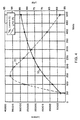
- Lumen output and lumens per watt for the lamp of FIG. 3 are plotted in FIG. 4 as a function of discharge power. Lumen output is indicated by curve 70, and lumens per watt are indicated by curve 72. The measurements were made at 40°C cold spot temperature after 100 hours of lamp operation. As shown in FIG. 4, lumen output increases with discharge power, while lumens per watt (LPW) peaks at 150 watts. At peak LPW, 14,000 lumens are produced with an efficacy (including ferrite core loss) of 92 LPW. The axial lumen density at this LPW is 163 lumen per cm (415 lumens per inch), which is 2.75 times greater than a conventional VHO fluorescent lamp.
- Discharge current at 150 watts is about 6 amperes. Operation with the parameters disclosed herein makes it possible for the lamp of the present invention to achieve relatively high lumen output, high efficacy and high axial lumen density simultaneously, thus making it an attractive alternative to conventional VHO fluorescent lamps and high intensity, high pressure discharge lamps.
- Discharge voltage is represented by curve 76; core loss is represented by curve 78; and power factor is represented by curve 80.
- Discharge voltage and core loss are referenced to the left ordinate, while power factor is referenced to the right ordinate.
- FIG. 5 emphasizes the importance of keeping the discharge voltage low.
- the core loss is 40% of total lamp power at 50 watts, while core loss is only about 6% of total lamp power at 150 watts.
- the increase in LPW with discharge power up to 150 watts shown in FIG. 4 is primarily related to the corresponding decrease in core loss.
- the remarkable overall performance of the lamp is due to the choice of operating parameters (primarily gas pressure, temperature, discharge tube diameter and discharge current).
- the BE2 core material is not considered to be the optimum core material. Measurements have indicated that the core loss may be reduced by almost a factor of two by using a premium core material such as 3F3 manufactured by Philips.
- the average electric field in the discharge is about 0,29 volts per cm (0.75 volts per inch).
- Such a small electric field in an electroded discharge would result in a rather inefficient light source, since the electrode drop would be appreciable (virtually no light comes from the electrode drop region) with respect to the total discharge voltage.
- an electroded discharge could not operate for a long period under these conditions.
- the lamp of the present invention is expected to have an extremely long life because of its electrodeless configuration.
Landscapes
- Physics & Mathematics (AREA)
- Engineering & Computer Science (AREA)
- Plasma & Fusion (AREA)
- Electromagnetism (AREA)
- Discharge Lamps And Accessories Thereof (AREA)
- Circuit Arrangements For Discharge Lamps (AREA)
Claims (17)
- Assemblage formant lampe électrique comportant :caractérisé par une pression gazeuse inférieure à 0,67 mbar (0,5 torr) et par un courant de décharge égal ou supérieur à 2 A.une lampe (10) sans électrode incluant une enveloppe (12) de lampe tubulaire, à boucle fermée, enfermant de la vapeur de mercure et un gaz tampon ;un noyau (22) de transformateur disposé autour de l'enveloppe (12) de lampe ; dans lequel le noyau (22) comporte un matériau de ferrite ;un enroulement (30) d'entrée disposé sur le noyau (22) de transformateur ; etune source de puissance haute fréquence couplée à l'enroulement d'entrée pour fournir de l'énergie haute fréquence suffisante à la vapeur de mercure et au gaz tampon pour produire dans l'enveloppe (12) de lampe une décharge ayant un courant de décharge ;
- Assemblage formant lampe électrique suivant la revendication 1, dans lequel la lampe (10) sans électrode comporte une substance (16) fluorescente sur une surface intérieure de l'enveloppe de lampe pour émettre du rayonnement dans un domaine de longueur d'onde déterminé à l'avance en réponse à du rayonnement ultraviolet émis par la décharge.
- Assemblage formant lampe électrique suivant la revendication 1, dans lequel la source (20) de puissance haute fréquence a une fréquence comprise entre 50 kHz et 3 MHz.
- Assemblage formant lampe électrique suivant la revendication 1, dans lequel la source (20) de puissance haute fréquence a une fréquence comprise entre 100 kHz et 400 kHz.
- Lampe électrique suivant la revendication 1, dans laquelle le gaz tampon comporte un gaz rare.
- Assemblage formant lampe électrique suivant la revendication 1, dans lequel le gaz tampon comporte du krypton.
- Assemblage formant lampe électrique suivant la revendication 1, dans lequel l'enveloppe de lampe tubulaire a une dimension en coupe transversale comprise entre 2,5 et 10 cm (1 à 4 pouces).
- Assemblage formant lampe électrique suivant la revendication 1, dans lequel le noyau (22) de transformateur a une configuration en tore.
- Assemblage formant lampe électrique suivant la revendication 1, comportant en outre un second noyau (24) de transformateur disposé autour de l'enveloppe (12) de lampe et un second enroulement (32) d'entrée disposé sur le second noyau (24) de transformateur et couplé à la source de puissance haute fréquence.
- Assemblage formant lampe électrique suivant la revendication 1, dans lequel l'enveloppe (12) de lampe a une forme ovale.
- Assemblage formant lampe électrique suivant la revendication 1, dans lequel l'enveloppe (52) de lampe comporte des premier et second tubes (54, 56) parallèles réunis à leurs extrémités pour former une boucle fermée.
- Assemblage formant lampe électrique suivant la revendication 1, dans lequel une perte de puissance de noyau est associée au noyau de transformateur, une puissance totale étant fournie par la source haute fréquence et la perte de puissance de noyau étant inférieure ou égale à 15% de la puissance totale fournie par la source de puissance haute fréquence.
- Assemblage formant lampe électrique suivant la revendication 1, dans lequel un rapport du volume de noyau de transformateur du noyau de transformateur sur la puissance de décharge de la lampe sans électrode est inférieur à 2 cm3 par watt.
- Assemblage formant lampe électrique suivant la revendication 1, dans lequel la pression dans l'enveloppe de lampe est inférieure ou égale à 0,27 mbar (0,2 torr) et le courant de décharge est égal ou supérieur à environ 5 A.
- Assemblage formant lampe électrique suivant la revendication 1, dans lequel l'enveloppe de lampe comporte une matériau transmetteur de l'ultraviolet et la lampe sans électrode émet du rayonnement ultraviolet.
- Procédé pour faire fonctionner une lampe électrique comportant une lampe sans électrode comportant une enveloppe de lampe tubulaire à boucle fermée enfermant un gaz tampon et de la vapeur de mercure, comportant les étapes qui consistent à :établir une pression de vapeur de mercure et de gaz tampon dans l'enveloppe de lampe inférieure à 0,67 mbar (0,5 torr) etcoupler par induction une énergie haute fréquence suffisante avec la vapeur de mercure et le gaz tampon pour produire dans l'enveloppe de lampe une décharge ayant un courant de décharge égal ou supérieur à environ 2 A.
- Procédé pour faire fonctionner une lampe électrique suivant la revendication 16, dans lequel l'étape qui consiste à établir une pression comporte l'étape qui consiste à établir une pression en vapeur de mercure et en gaz tampon inférieure ou égale à 0,27 mbar (0,2 torr) et l'étape qui consiste à coupler par induction de l'énergie haute fréquence comporte l'étape qui consiste à coupler par induction une énergie haute fréquence suffisante pour produire un courant de décharge égal ou supérieur à environ 5 A.
Applications Claiming Priority (5)
| Application Number | Priority Date | Filing Date | Title |
|---|---|---|---|
| US3827 | 1979-01-16 | ||
| US382795P | 1995-09-15 | 1995-09-15 | |
| US624043 | 1996-03-27 | ||
| US08/624,043 US5834905A (en) | 1995-09-15 | 1996-03-27 | High intensity electrodeless low pressure light source driven by a transformer core arrangement |
| PCT/EP1996/003180 WO1997010610A1 (fr) | 1995-09-15 | 1996-07-18 | Source lumineuse basse pression, haute intensite, sans electrodes |
Publications (2)
| Publication Number | Publication Date |
|---|---|
| EP0806054A1 EP0806054A1 (fr) | 1997-11-12 |
| EP0806054B1 true EP0806054B1 (fr) | 2002-03-27 |
Family
ID=26672245
Family Applications (1)
| Application Number | Title | Priority Date | Filing Date |
|---|---|---|---|
| EP96927043A Expired - Lifetime EP0806054B1 (fr) | 1995-09-15 | 1996-07-18 | Source lumineuse ou lampe electrique sans electrode a basse pression et a haute intensite et procede de mise en oeuvre d' une telle lampe |
Country Status (8)
| Country | Link |
|---|---|
| US (1) | US5834905A (fr) |
| EP (1) | EP0806054B1 (fr) |
| KR (1) | KR100356960B1 (fr) |
| CN (1) | CN1155049C (fr) |
| AU (1) | AU705741B2 (fr) |
| DE (1) | DE69620153T2 (fr) |
| HU (1) | HU222165B1 (fr) |
| WO (1) | WO1997010610A1 (fr) |
Cited By (1)
| Publication number | Priority date | Publication date | Assignee | Title |
|---|---|---|---|---|
| DE10216092A1 (de) * | 2002-04-11 | 2003-10-30 | Schott Glas | Verbundmaterial aus einem Substratmaterial und einem Barriereschichtmaterial |
Families Citing this family (80)
| Publication number | Priority date | Publication date | Assignee | Title |
|---|---|---|---|---|
| US5722549A (en) * | 1996-05-22 | 1998-03-03 | Osram Sylvania Inc. | Closed-loop tubular lamp envelope and method of manufacture |
| US7569790B2 (en) | 1997-06-26 | 2009-08-04 | Mks Instruments, Inc. | Method and apparatus for processing metal bearing gases |
| US6150628A (en) | 1997-06-26 | 2000-11-21 | Applied Science And Technology, Inc. | Toroidal low-field reactive gas source |
| US6388226B1 (en) | 1997-06-26 | 2002-05-14 | Applied Science And Technology, Inc. | Toroidal low-field reactive gas source |
| US8779322B2 (en) | 1997-06-26 | 2014-07-15 | Mks Instruments Inc. | Method and apparatus for processing metal bearing gases |
| US7166816B1 (en) | 1997-06-26 | 2007-01-23 | Mks Instruments, Inc. | Inductively-coupled torodial plasma source |
| US6815633B1 (en) | 1997-06-26 | 2004-11-09 | Applied Science & Technology, Inc. | Inductively-coupled toroidal plasma source |
| US6175197B1 (en) * | 1997-10-14 | 2001-01-16 | Osram Sylvania Inc. | Electrodeless lamp having thermal bridge between transformer core and amalgam |
| DE19805314A1 (de) | 1998-02-10 | 1999-08-19 | Patent Treuhand Ges Fuer Elektrische Gluehlampen Mbh | Schaltungsanordnung zum Betrieb mindestens einer elektrodenlosen Entladungslampe |
| US6288490B1 (en) | 1999-02-24 | 2001-09-11 | Matsoshita Electric Works Research And Development Laboratory Inc | Ferrite-free electrodeless fluorescent lamp |
| US20020067129A1 (en) * | 1999-05-03 | 2002-06-06 | John C. Chamberlain | Ferrite core for electrodeless flourescent lamp operating at 50-500 khz |
| US7126450B2 (en) | 1999-06-21 | 2006-10-24 | Access Business Group International Llc | Inductively powered apparatus |
| US7385357B2 (en) | 1999-06-21 | 2008-06-10 | Access Business Group International Llc | Inductively coupled ballast circuit |
| US7612528B2 (en) | 1999-06-21 | 2009-11-03 | Access Business Group International Llc | Vehicle interface |
| US6731071B2 (en) * | 1999-06-21 | 2004-05-04 | Access Business Group International Llc | Inductively powered lamp assembly |
| US6825620B2 (en) | 1999-06-21 | 2004-11-30 | Access Business Group International Llc | Inductively coupled ballast circuit |
| DE19944575B4 (de) * | 1999-09-17 | 2005-05-04 | Patent-Treuhand-Gesellschaft für elektrische Glühlampen mbH | Beleuchtungsvorrichtung mit mindestens einer elektrodenlosen Entladungslampe |
| GB2356081A (en) * | 1999-09-20 | 2001-05-09 | Osram Sylvania Inc | Electrodeless discharge lamp having self-resonant filter choke |
| US6362570B1 (en) | 1999-10-19 | 2002-03-26 | Matsushita Electric Works Research And Development Laboratories, Inc. | High frequency ferrite-free electrodeless flourescent lamp with axially uniform plasma |
| JP2004504708A (ja) * | 2000-07-21 | 2004-02-12 | オスラム−シルヴェニア インコーポレイテッド | アーク検出及び電子安定器の保護のための方法及び装置 |
| DE10196490T1 (de) * | 2000-08-10 | 2003-10-16 | Osram Sylvania Inc | Stark belastete Leuchtstofflampe |
| US20020180356A1 (en) * | 2001-04-05 | 2002-12-05 | Kirkpatrick Douglas A. | Sulfur lamp |
| KR20020080787A (ko) * | 2001-04-17 | 2002-10-26 | 강성진 | 3차원 구조를 갖는 무전극 형광 램프 |
| US6522085B2 (en) | 2001-07-16 | 2003-02-18 | Matsushita Research And Development Laboratories Inc | High light output electrodeless fluorescent closed-loop lamp |
| US6528953B1 (en) * | 2001-09-25 | 2003-03-04 | Osram Sylvania Inc. | Amalgam retainer |
| US6605889B2 (en) * | 2001-10-24 | 2003-08-12 | Matsushita Electric Works Ltd | Electrodeless low pressure lamp with multiple ferrite cores and coils |
| US6670768B1 (en) * | 2002-07-22 | 2003-12-30 | Osram Sylvania Inc. | Blue incandescent general purpose lamp |
| US6696802B1 (en) * | 2002-08-22 | 2004-02-24 | Fusion Uv Systems Inc. | Radio frequency driven ultra-violet lamp |
| US8053700B2 (en) * | 2003-04-16 | 2011-11-08 | Mks Instruments, Inc. | Applicators and cooling systems for a plasma device |
| US6872909B2 (en) * | 2003-04-16 | 2005-03-29 | Applied Science And Technology, Inc. | Toroidal low-field reactive gas and plasma source having a dielectric vacuum vessel |
| CN2645232Y (zh) * | 2003-08-04 | 2004-09-29 | 上海宏源照明电器有限公司 | 具有立体造型灯管的电磁感应灯 |
| WO2005098905A1 (fr) * | 2004-04-09 | 2005-10-20 | Shanghai Hongyuan Lighting & Electrical Equipment Co., Ltd. | Lampe a induction electromagnetique comprenant une structure amelioree de tube de lampe |
| US7462951B1 (en) | 2004-08-11 | 2008-12-09 | Access Business Group International Llc | Portable inductive power station |
| US7303307B2 (en) * | 2004-10-06 | 2007-12-04 | Osram Sylvania Inc. | Electrodeless lamp with incorporated reflector |
| US7408324B2 (en) | 2004-10-27 | 2008-08-05 | Access Business Group International Llc | Implement rack and system for energizing implements |
| CN100435267C (zh) * | 2004-12-22 | 2008-11-19 | 李进 | 内穿组合式磁能发生器及其磁能灯 |
| CN100447939C (zh) * | 2004-12-22 | 2008-12-31 | 李进 | 外包组合式磁能发生器及其磁能灯 |
| US20060186785A1 (en) * | 2005-02-23 | 2006-08-24 | Osram Sylvania Inc. | Method of improving low temperature lumen maintenance of an electrodeless lamp and electrodeless lamp with improved low temperature lumen maintenance |
| KR100711495B1 (ko) * | 2005-07-07 | 2007-04-24 | 금호전기주식회사 | 안내홈이 성형된 링코어를 가지는 환형/둥근형 무전극 램프 |
| KR100727040B1 (ko) | 2005-09-09 | 2007-06-12 | 금호전기주식회사 | 듀얼 브리지 무전극 형광램프의 램프 밀봉체 제조 방법 |
| DE102005050306B3 (de) * | 2005-10-20 | 2007-03-15 | Minebea Co., Ltd. | Elektrodenlose Gasentladungslampe |
| US20070132355A1 (en) * | 2005-12-09 | 2007-06-14 | Palmer Fred L | Low profile, low loss closed-loop electrodeless fluorescent lamp |
| CN101443883A (zh) * | 2006-05-17 | 2009-05-27 | 奥斯兰姆施尔凡尼亚公司 | 无电极的光疗灯 |
| US7969096B2 (en) | 2006-12-15 | 2011-06-28 | Mks Instruments, Inc. | Inductively-coupled plasma source |
| US7737613B2 (en) * | 2007-07-31 | 2010-06-15 | U.S. Energy Technologies, Inc. | Electrodeless lamp and core having indented coil winding section for use with tubular lamp envelope |
| US7772753B2 (en) * | 2007-09-04 | 2010-08-10 | U.S. Energy Technologies, Inc. | Electrodeless lamp core assembly including coil bobbin and lamp envelope protector |
| KR101039570B1 (ko) * | 2009-03-04 | 2011-06-09 | (주)이텍 | 전기 램프 어셈블리 |
| US8487544B2 (en) * | 2010-09-29 | 2013-07-16 | Osram Sylvania Inc. | Power splitter circuit for electrodeless lamp |
| CN102347202A (zh) * | 2011-09-21 | 2012-02-08 | 王家诚 | 大功率外耦合无极紫外灯 |
| US20130118589A1 (en) * | 2011-11-15 | 2013-05-16 | Mks Instruments, Inc. | Toroidal Plasma Channel with Varying Cross-Section Areas Along the Channel |
| US8502482B1 (en) | 2011-12-06 | 2013-08-06 | John Yeh | Compact induction lamp |
| CN102664133A (zh) * | 2012-05-10 | 2012-09-12 | 张文知 | 强化光合作用的无极灯灯管 |
| CN103426719A (zh) * | 2012-05-20 | 2013-12-04 | 烟台同辉照明科技有限公司 | 低压低频无极黑光灯 |
| CN102751167A (zh) * | 2012-07-16 | 2012-10-24 | 绍兴文理学院 | 一种无极灯 |
| US9245734B2 (en) | 2012-11-26 | 2016-01-26 | Lucidity Lights, Inc. | Fast start induction RF fluorescent lamp with burst-mode dimming |
| US10128101B2 (en) | 2012-11-26 | 2018-11-13 | Lucidity Lights, Inc. | Dimmable induction RF fluorescent lamp with reduced electromagnetic interference |
| US8941304B2 (en) | 2012-11-26 | 2015-01-27 | Lucidity Lights, Inc. | Fast start dimmable induction RF fluorescent light bulb |
| US9460907B2 (en) | 2012-11-26 | 2016-10-04 | Lucidity Lights, Inc. | Induction RF fluorescent lamp with load control for external dimming device |
| US10529551B2 (en) | 2012-11-26 | 2020-01-07 | Lucidity Lights, Inc. | Fast start fluorescent light bulb |
| US8872426B2 (en) | 2012-11-26 | 2014-10-28 | Lucidity Lights, Inc. | Arrangements and methods for triac dimming of gas discharge lamps powered by electronic ballasts |
| US9305765B2 (en) | 2012-11-26 | 2016-04-05 | Lucidity Lights, Inc. | High frequency induction lighting |
| US9161422B2 (en) | 2012-11-26 | 2015-10-13 | Lucidity Lights, Inc. | Electronic ballast having improved power factor and total harmonic distortion |
| US10141179B2 (en) | 2012-11-26 | 2018-11-27 | Lucidity Lights, Inc. | Fast start RF induction lamp with metallic structure |
| US9524861B2 (en) | 2012-11-26 | 2016-12-20 | Lucidity Lights, Inc. | Fast start RF induction lamp |
| US9209008B2 (en) | 2012-11-26 | 2015-12-08 | Lucidity Lights, Inc. | Fast start induction RF fluorescent light bulb |
| US8698413B1 (en) * | 2012-11-26 | 2014-04-15 | Lucidity Lights, Inc. | RF induction lamp with reduced electromagnetic interference |
| US9129792B2 (en) | 2012-11-26 | 2015-09-08 | Lucidity Lights, Inc. | Fast start induction RF fluorescent lamp with reduced electromagnetic interference |
| US20140375203A1 (en) | 2012-11-26 | 2014-12-25 | Lucidity Lights, Inc. | Induction rf fluorescent lamp with helix mount |
| US9129791B2 (en) * | 2012-11-26 | 2015-09-08 | Lucidity Lights, Inc. | RF coupler stabilization in an induction RF fluorescent light bulb |
| USD745981S1 (en) | 2013-07-19 | 2015-12-22 | Lucidity Lights, Inc. | Inductive lamp |
| USD745982S1 (en) | 2013-07-19 | 2015-12-22 | Lucidity Lights, Inc. | Inductive lamp |
| USD746490S1 (en) | 2013-07-19 | 2015-12-29 | Lucidity Lights, Inc. | Inductive lamp |
| USD747009S1 (en) | 2013-08-02 | 2016-01-05 | Lucidity Lights, Inc. | Inductive lamp |
| USD747507S1 (en) | 2013-08-02 | 2016-01-12 | Lucidity Lights, Inc. | Inductive lamp |
| CN109074999B (zh) | 2016-03-21 | 2022-01-21 | 特斯洛有限公司 | 低压气体放电辐射源及其制造方法 |
| USD854198S1 (en) | 2017-12-28 | 2019-07-16 | Lucidity Lights, Inc. | Inductive lamp |
| US10236174B1 (en) | 2017-12-28 | 2019-03-19 | Lucidity Lights, Inc. | Lumen maintenance in fluorescent lamps |
| CA3184220A1 (fr) * | 2020-06-25 | 2021-12-30 | Pierre F. Thibault | Dispositif a plasma sans electrode |
| US12027426B2 (en) | 2021-01-29 | 2024-07-02 | Applied Materials, Inc. | Image-based digital control of plasma processing |
| US12068134B2 (en) | 2021-01-29 | 2024-08-20 | Applied Materials, Inc. | Digital control of plasma processing |
Family Cites Families (9)
| Publication number | Priority date | Publication date | Assignee | Title |
|---|---|---|---|---|
| US3500118A (en) * | 1967-07-17 | 1970-03-10 | Gen Electric | Electrodeless gaseous electric discharge devices utilizing ferrite cores |
| US3987334A (en) * | 1975-01-20 | 1976-10-19 | General Electric Company | Integrally ballasted electrodeless fluorescent lamp |
| US4017764A (en) * | 1975-01-20 | 1977-04-12 | General Electric Company | Electrodeless fluorescent lamp having a radio frequency gas discharge excited by a closed loop magnetic core |
| US4253047A (en) * | 1977-05-23 | 1981-02-24 | General Electric Company | Starting electrodes for solenoidal electric field discharge lamps |
| US4180763A (en) * | 1978-01-25 | 1979-12-25 | General Electric Company | High intensity discharge lamp geometries |
| US4864194A (en) * | 1987-05-25 | 1989-09-05 | Matsushita Electric Works, Ltd. | Electrodeless discharge lamp device |
| US5146140A (en) * | 1991-06-18 | 1992-09-08 | Gte Products Corporation | Method and apparatus to reduce Hg loss in rf capacitively coupled gas discharges |
| JP3408588B2 (ja) * | 1993-09-22 | 2003-05-19 | 池田電機株式会社 | 無電極放電灯点灯装置 |
| JPH0794152A (ja) * | 1993-09-27 | 1995-04-07 | Ikeda Electric Co Ltd | 無電極放電灯 |
-
1996
- 1996-03-27 US US08/624,043 patent/US5834905A/en not_active Expired - Lifetime
- 1996-07-18 KR KR1019970701936A patent/KR100356960B1/ko not_active Ceased
- 1996-07-18 DE DE69620153T patent/DE69620153T2/de not_active Expired - Lifetime
- 1996-07-18 HU HU9701872A patent/HU222165B1/hu active IP Right Grant
- 1996-07-18 WO PCT/EP1996/003180 patent/WO1997010610A1/fr not_active Ceased
- 1996-07-18 CN CNB961910798A patent/CN1155049C/zh not_active Ceased
- 1996-07-18 AU AU67013/96A patent/AU705741B2/en not_active Ceased
- 1996-07-18 EP EP96927043A patent/EP0806054B1/fr not_active Expired - Lifetime
Cited By (1)
| Publication number | Priority date | Publication date | Assignee | Title |
|---|---|---|---|---|
| DE10216092A1 (de) * | 2002-04-11 | 2003-10-30 | Schott Glas | Verbundmaterial aus einem Substratmaterial und einem Barriereschichtmaterial |
Also Published As
| Publication number | Publication date |
|---|---|
| HUP9701872A2 (hu) | 2000-09-28 |
| HUP9701872A3 (en) | 2000-12-28 |
| AU6701396A (en) | 1997-04-01 |
| KR100356960B1 (ko) | 2003-03-03 |
| DE69620153D1 (de) | 2002-05-02 |
| CN1165582A (zh) | 1997-11-19 |
| HU222165B1 (hu) | 2003-04-28 |
| CN1155049C (zh) | 2004-06-23 |
| US5834905A (en) | 1998-11-10 |
| EP0806054A1 (fr) | 1997-11-12 |
| AU705741B2 (en) | 1999-06-03 |
| WO1997010610A1 (fr) | 1997-03-20 |
| DE69620153T2 (de) | 2002-08-01 |
| KR970706597A (ko) | 1997-11-03 |
Similar Documents
| Publication | Publication Date | Title |
|---|---|---|
| EP0806054B1 (fr) | Source lumineuse ou lampe electrique sans electrode a basse pression et a haute intensite et procede de mise en oeuvre d' une telle lampe | |
| US5886472A (en) | Electrodeless lamp having compensation loop for suppression of magnetic interference | |
| US5300860A (en) | Capacitively coupled RF fluorescent lamp with RF magnetic enhancement | |
| CA1149079A (fr) | Lampe fluorescent compacte, et mode d'excitation connexe | |
| US4117378A (en) | Reflective coating for external core electrodeless fluorescent lamp | |
| US5325024A (en) | Light source including parallel driven low pressure RF fluorescent lamps | |
| EP0910112B1 (fr) | Lampe sans électrode interne comportant un pont thermique entre le noyau du transformateur et l'amalgame | |
| US5717290A (en) | Starting flag structure for tubular low pressure discharge lamps | |
| US6522085B2 (en) | High light output electrodeless fluorescent closed-loop lamp | |
| CA2185267C (fr) | Source lumineuse basse pression, haute intensite, sans electrode | |
| US7800289B2 (en) | Electrodeless gas discharge lamp | |
| EP0593312B1 (fr) | Source de lumière fluorescente | |
| US6362570B1 (en) | High frequency ferrite-free electrodeless flourescent lamp with axially uniform plasma | |
| US4233541A (en) | Start winding for solenoidal electric field discharge lamps | |
| JP3680741B2 (ja) | 無電極蛍光ランプ | |
| US5760547A (en) | Multiple-discharge electrodeless fluorescent lamp | |
| JP3489211B2 (ja) | 無電極放電ランプ | |
| KR101039570B1 (ko) | 전기 램프 어셈블리 | |
| JP3178259B2 (ja) | 無電極放電ランプ | |
| JPH05347144A (ja) | 無電極放電灯 |
Legal Events
| Date | Code | Title | Description |
|---|---|---|---|
| PUAI | Public reference made under article 153(3) epc to a published international application that has entered the european phase |
Free format text: ORIGINAL CODE: 0009012 |
|
| 17P | Request for examination filed |
Effective date: 19970506 |
|
| AK | Designated contracting states |
Kind code of ref document: A1 Designated state(s): BE CH DE FR GB IT LI NL |
|
| 17Q | First examination report despatched |
Effective date: 19991022 |
|
| RTI1 | Title (correction) |
Free format text: LOW PRESSURE, HIGH INTENSITY ELECTRODELESS LIGHT SOURCE OR ELECTRIC LAMP AND METHOD FOR OPERATING THE SAME |
|
| RTI1 | Title (correction) |
Free format text: LOW PRESSURE, HIGH INTENSITY ELECTRODELESS LIGHT SOURCE OR ELECTRIC LAMP AND METHOD FOR OPERATING THE SAME |
|
| GRAG | Despatch of communication of intention to grant |
Free format text: ORIGINAL CODE: EPIDOS AGRA |
|
| GRAG | Despatch of communication of intention to grant |
Free format text: ORIGINAL CODE: EPIDOS AGRA |
|
| GRAH | Despatch of communication of intention to grant a patent |
Free format text: ORIGINAL CODE: EPIDOS IGRA |
|
| REG | Reference to a national code |
Ref country code: GB Ref legal event code: IF02 |
|
| GRAH | Despatch of communication of intention to grant a patent |
Free format text: ORIGINAL CODE: EPIDOS IGRA |
|
| GRAA | (expected) grant |
Free format text: ORIGINAL CODE: 0009210 |
|
| AK | Designated contracting states |
Kind code of ref document: B1 Designated state(s): BE CH DE FR GB IT LI NL |
|
| REG | Reference to a national code |
Ref country code: CH Ref legal event code: NV Representative=s name: SIEMENS SCHWEIZ AG Ref country code: CH Ref legal event code: EP |
|
| REF | Corresponds to: |
Ref document number: 69620153 Country of ref document: DE Date of ref document: 20020502 |
|
| ET | Fr: translation filed | ||
| PLBE | No opposition filed within time limit |
Free format text: ORIGINAL CODE: 0009261 |
|
| STAA | Information on the status of an ep patent application or granted ep patent |
Free format text: STATUS: NO OPPOSITION FILED WITHIN TIME LIMIT |
|
| 26N | No opposition filed |
Effective date: 20021230 |
|
| REG | Reference to a national code |
Ref country code: CH Ref legal event code: PCAR Free format text: SIEMENS SCHWEIZ AG;INTELLECTUAL PROPERTY FREILAGERSTRASSE 40;8047 ZUERICH (CH) |
|
| REG | Reference to a national code |
Ref country code: DE Ref legal event code: R081 Ref document number: 69620153 Country of ref document: DE Owner name: OSRAM GMBH, DE Free format text: FORMER OWNER: OSRAM GESELLSCHAFT MIT BESCHRAENKTER HAFTUNG, 81543 MUENCHEN, DE Effective date: 20111130 |
|
| REG | Reference to a national code |
Ref country code: DE Ref legal event code: R081 Ref document number: 69620153 Country of ref document: DE Owner name: OSRAM GMBH, DE Free format text: FORMER OWNER: OSRAM AG, 81543 MUENCHEN, DE Effective date: 20130205 |
|
| REG | Reference to a national code |
Ref country code: DE Ref legal event code: R081 Ref document number: 69620153 Country of ref document: DE Owner name: OSRAM GMBH, DE Free format text: FORMER OWNER: OSRAM GMBH, 81543 MUENCHEN, DE Effective date: 20130822 |
|
| REG | Reference to a national code |
Ref country code: FR Ref legal event code: PLFP Year of fee payment: 20 |
|
| PGFP | Annual fee paid to national office [announced via postgrant information from national office to epo] |
Ref country code: FR Payment date: 20150626 Year of fee payment: 20 |
|
| PGFP | Annual fee paid to national office [announced via postgrant information from national office to epo] |
Ref country code: NL Payment date: 20150721 Year of fee payment: 20 |
|
| PGFP | Annual fee paid to national office [announced via postgrant information from national office to epo] |
Ref country code: CH Payment date: 20150721 Year of fee payment: 20 Ref country code: GB Payment date: 20150721 Year of fee payment: 20 Ref country code: DE Payment date: 20150721 Year of fee payment: 20 |
|
| PGFP | Annual fee paid to national office [announced via postgrant information from national office to epo] |
Ref country code: BE Payment date: 20150721 Year of fee payment: 20 |
|
| PGFP | Annual fee paid to national office [announced via postgrant information from national office to epo] |
Ref country code: IT Payment date: 20150727 Year of fee payment: 20 |
|
| REG | Reference to a national code |
Ref country code: DE Ref legal event code: R071 Ref document number: 69620153 Country of ref document: DE |
|
| REG | Reference to a national code |
Ref country code: NL Ref legal event code: MK Effective date: 20160717 |
|
| REG | Reference to a national code |
Ref country code: CH Ref legal event code: PL |
|
| REG | Reference to a national code |
Ref country code: GB Ref legal event code: PE20 Expiry date: 20160717 |
|
| PG25 | Lapsed in a contracting state [announced via postgrant information from national office to epo] |
Ref country code: GB Free format text: LAPSE BECAUSE OF EXPIRATION OF PROTECTION Effective date: 20160717 |