EP0805747B1 - Method for making honeycomb core composite articles - Google Patents
Method for making honeycomb core composite articles Download PDFInfo
- Publication number
- EP0805747B1 EP0805747B1 EP95920367A EP95920367A EP0805747B1 EP 0805747 B1 EP0805747 B1 EP 0805747B1 EP 95920367 A EP95920367 A EP 95920367A EP 95920367 A EP95920367 A EP 95920367A EP 0805747 B1 EP0805747 B1 EP 0805747B1
- Authority
- EP
- European Patent Office
- Prior art keywords
- composite
- composite skin
- honeycomb core
- precured
- skin
- Prior art date
- Legal status (The legal status is an assumption and is not a legal conclusion. Google has not performed a legal analysis and makes no representation as to the accuracy of the status listed.)
- Expired - Lifetime
Links
- 239000002131 composite material Substances 0.000 title claims abstract description 185
- 238000000034 method Methods 0.000 title claims abstract description 44
- 230000002093 peripheral effect Effects 0.000 claims abstract description 26
- 239000000853 adhesive Substances 0.000 claims description 18
- 230000001070 adhesive effect Effects 0.000 claims description 16
- 238000006073 displacement reaction Methods 0.000 claims description 8
- 230000000694 effects Effects 0.000 claims description 8
- 230000013011 mating Effects 0.000 claims description 8
- 238000009966 trimming Methods 0.000 claims description 6
- 238000007666 vacuum forming Methods 0.000 claims description 4
- 241000264877 Hippospongia communis Species 0.000 description 68
- 238000000465 moulding Methods 0.000 description 18
- 239000000835 fiber Substances 0.000 description 11
- 238000004519 manufacturing process Methods 0.000 description 11
- 210000004027 cell Anatomy 0.000 description 7
- 239000000463 material Substances 0.000 description 7
- 239000011347 resin Substances 0.000 description 7
- 229920005989 resin Polymers 0.000 description 7
- 239000011159 matrix material Substances 0.000 description 6
- 238000005056 compaction Methods 0.000 description 5
- 230000006641 stabilisation Effects 0.000 description 5
- 238000011105 stabilization Methods 0.000 description 5
- OKTJSMMVPCPJKN-UHFFFAOYSA-N Carbon Chemical compound [C] OKTJSMMVPCPJKN-UHFFFAOYSA-N 0.000 description 4
- 239000004812 Fluorinated ethylene propylene Substances 0.000 description 4
- 229920003235 aromatic polyamide Polymers 0.000 description 4
- 238000012423 maintenance Methods 0.000 description 4
- 229910052751 metal Inorganic materials 0.000 description 4
- 239000002184 metal Substances 0.000 description 4
- 229920009441 perflouroethylene propylene Polymers 0.000 description 4
- ISWSIDIOOBJBQZ-UHFFFAOYSA-N phenol group Chemical group C1(=CC=CC=C1)O ISWSIDIOOBJBQZ-UHFFFAOYSA-N 0.000 description 4
- 241000531908 Aramides Species 0.000 description 3
- 239000004593 Epoxy Substances 0.000 description 3
- 229920000271 Kevlar® Polymers 0.000 description 3
- 229920000784 Nomex Polymers 0.000 description 3
- 238000004140 cleaning Methods 0.000 description 3
- 239000011152 fibreglass Substances 0.000 description 3
- 229910002804 graphite Inorganic materials 0.000 description 3
- 239000010439 graphite Substances 0.000 description 3
- 239000004763 nomex Substances 0.000 description 3
- 230000000737 periodic effect Effects 0.000 description 3
- 230000002787 reinforcement Effects 0.000 description 3
- 239000012260 resinous material Substances 0.000 description 3
- 230000002745 absorbent Effects 0.000 description 2
- 239000002250 absorbent Substances 0.000 description 2
- 238000013459 approach Methods 0.000 description 2
- 238000005452 bending Methods 0.000 description 2
- 230000015572 biosynthetic process Effects 0.000 description 2
- 238000004891 communication Methods 0.000 description 2
- 238000010276 construction Methods 0.000 description 2
- 238000013461 design Methods 0.000 description 2
- 239000004744 fabric Substances 0.000 description 2
- 239000003733 fiber-reinforced composite Substances 0.000 description 2
- 239000012530 fluid Substances 0.000 description 2
- 239000006260 foam Substances 0.000 description 2
- -1 i.e. Substances 0.000 description 2
- 230000002401 inhibitory effect Effects 0.000 description 2
- 238000012986 modification Methods 0.000 description 2
- 230000004048 modification Effects 0.000 description 2
- 230000036961 partial effect Effects 0.000 description 2
- 238000012545 processing Methods 0.000 description 2
- 230000008439 repair process Effects 0.000 description 2
- 239000003039 volatile agent Substances 0.000 description 2
- LFQSCWFLJHTTHZ-UHFFFAOYSA-N Ethanol Chemical compound CCO LFQSCWFLJHTTHZ-UHFFFAOYSA-N 0.000 description 1
- 238000007792 addition Methods 0.000 description 1
- 230000002411 adverse Effects 0.000 description 1
- 229910052782 aluminium Inorganic materials 0.000 description 1
- XAGFODPZIPBFFR-UHFFFAOYSA-N aluminium Chemical compound [Al] XAGFODPZIPBFFR-UHFFFAOYSA-N 0.000 description 1
- 239000004760 aramid Substances 0.000 description 1
- 229920006231 aramid fiber Polymers 0.000 description 1
- 239000011230 binding agent Substances 0.000 description 1
- 229910052799 carbon Inorganic materials 0.000 description 1
- 210000002421 cell wall Anatomy 0.000 description 1
- 230000001413 cellular effect Effects 0.000 description 1
- 230000001010 compromised effect Effects 0.000 description 1
- 238000007596 consolidation process Methods 0.000 description 1
- 238000005520 cutting process Methods 0.000 description 1
- 229920001971 elastomer Polymers 0.000 description 1
- 239000000806 elastomer Substances 0.000 description 1
- 231100001261 hazardous Toxicity 0.000 description 1
- 230000000977 initiatory effect Effects 0.000 description 1
- 230000000670 limiting effect Effects 0.000 description 1
- 238000003754 machining Methods 0.000 description 1
- 239000012528 membrane Substances 0.000 description 1
- 230000007935 neutral effect Effects 0.000 description 1
- 230000003071 parasitic effect Effects 0.000 description 1
- 239000011148 porous material Substances 0.000 description 1
- 238000002360 preparation method Methods 0.000 description 1
- 230000008569 process Effects 0.000 description 1
- 230000001681 protective effect Effects 0.000 description 1
- 238000007789 sealing Methods 0.000 description 1
- 238000012546 transfer Methods 0.000 description 1
- 238000001721 transfer moulding Methods 0.000 description 1
- 230000007704 transition Effects 0.000 description 1
Images


Classifications
-
- B—PERFORMING OPERATIONS; TRANSPORTING
- B29—WORKING OF PLASTICS; WORKING OF SUBSTANCES IN A PLASTIC STATE IN GENERAL
- B29C—SHAPING OR JOINING OF PLASTICS; SHAPING OF MATERIAL IN A PLASTIC STATE, NOT OTHERWISE PROVIDED FOR; AFTER-TREATMENT OF THE SHAPED PRODUCTS, e.g. REPAIRING
- B29C70/00—Shaping composites, i.e. plastics material comprising reinforcements, fillers or preformed parts, e.g. inserts
- B29C70/04—Shaping composites, i.e. plastics material comprising reinforcements, fillers or preformed parts, e.g. inserts comprising reinforcements only, e.g. self-reinforcing plastics
- B29C70/28—Shaping operations therefor
- B29C70/30—Shaping by lay-up, i.e. applying fibres, tape or broadsheet on a mould, former or core; Shaping by spray-up, i.e. spraying of fibres on a mould, former or core
- B29C70/34—Shaping by lay-up, i.e. applying fibres, tape or broadsheet on a mould, former or core; Shaping by spray-up, i.e. spraying of fibres on a mould, former or core and shaping or impregnating by compression, i.e. combined with compressing after the lay-up operation
- B29C70/342—Shaping by lay-up, i.e. applying fibres, tape or broadsheet on a mould, former or core; Shaping by spray-up, i.e. spraying of fibres on a mould, former or core and shaping or impregnating by compression, i.e. combined with compressing after the lay-up operation using isostatic pressure
-
- B—PERFORMING OPERATIONS; TRANSPORTING
- B29—WORKING OF PLASTICS; WORKING OF SUBSTANCES IN A PLASTIC STATE IN GENERAL
- B29C—SHAPING OR JOINING OF PLASTICS; SHAPING OF MATERIAL IN A PLASTIC STATE, NOT OTHERWISE PROVIDED FOR; AFTER-TREATMENT OF THE SHAPED PRODUCTS, e.g. REPAIRING
- B29C70/00—Shaping composites, i.e. plastics material comprising reinforcements, fillers or preformed parts, e.g. inserts
- B29C70/04—Shaping composites, i.e. plastics material comprising reinforcements, fillers or preformed parts, e.g. inserts comprising reinforcements only, e.g. self-reinforcing plastics
- B29C70/28—Shaping operations therefor
- B29C70/40—Shaping or impregnating by compression not applied
- B29C70/42—Shaping or impregnating by compression not applied for producing articles of definite length, i.e. discrete articles
- B29C70/44—Shaping or impregnating by compression not applied for producing articles of definite length, i.e. discrete articles using isostatic pressure, e.g. pressure difference-moulding, vacuum bag-moulding, autoclave-moulding or expanding rubber-moulding
-
- B—PERFORMING OPERATIONS; TRANSPORTING
- B29—WORKING OF PLASTICS; WORKING OF SUBSTANCES IN A PLASTIC STATE IN GENERAL
- B29C—SHAPING OR JOINING OF PLASTICS; SHAPING OF MATERIAL IN A PLASTIC STATE, NOT OTHERWISE PROVIDED FOR; AFTER-TREATMENT OF THE SHAPED PRODUCTS, e.g. REPAIRING
- B29C70/00—Shaping composites, i.e. plastics material comprising reinforcements, fillers or preformed parts, e.g. inserts
- B29C70/04—Shaping composites, i.e. plastics material comprising reinforcements, fillers or preformed parts, e.g. inserts comprising reinforcements only, e.g. self-reinforcing plastics
- B29C70/28—Shaping operations therefor
- B29C70/54—Component parts, details or accessories; Auxiliary operations, e.g. feeding or storage of prepregs or SMC after impregnation or during ageing
- B29C70/543—Fixing the position or configuration of fibrous reinforcements before or during moulding
-
- B—PERFORMING OPERATIONS; TRANSPORTING
- B29—WORKING OF PLASTICS; WORKING OF SUBSTANCES IN A PLASTIC STATE IN GENERAL
- B29D—PRODUCING PARTICULAR ARTICLES FROM PLASTICS OR FROM SUBSTANCES IN A PLASTIC STATE
- B29D24/00—Producing articles with hollow walls
- B29D24/002—Producing articles with hollow walls formed with structures, e.g. cores placed between two plates or sheets, e.g. partially filled
- B29D24/005—Producing articles with hollow walls formed with structures, e.g. cores placed between two plates or sheets, e.g. partially filled the structure having joined ribs, e.g. honeycomb
- B29D24/007—Producing articles with hollow walls formed with structures, e.g. cores placed between two plates or sheets, e.g. partially filled the structure having joined ribs, e.g. honeycomb and a chamfered edge
Definitions
- the present invention relates to manufacturing honeycomb core composite articles, and more particularly, to an improved method of manufacturing such composite articles wherein the honeycomb core thereof is accurately located and substantially distortion-free.
- Honeycomb core (HC) composite articles are commonly utilized for fabricating aerospace structures due to their advantageous strength to weight ratio.
- Honeycomb core (HC) composite articles are typically comprised of upper and lower composite skins, i.e., fiber reinforced resin matrix laminates, that are separated and stabilized by the honeycomb core. Due to the high bending stiffness and compressive strength properties of HC composite articles, i.e., the honeycomb core functions as a shear web and spaces the composite skins from the bending neutral axis, HC composite articles have particular utility in aerospace applications such as aircraft fuselage panels and door structures. The high strength and low weight of such construction results in lower overall aircraft system weight.
- HC composite articles may be fabricated utilizing various composite forming methods.
- the most commonly employed technique involves the use of a vacuum bag molding assembly wherein an impervious membrane or "vacuum bag” is employed for consolidating the composite skins and ensuring proper adhesion thereof to the centrally disposed honeycomb core.
- the lower composite skin, honeycomb core, and upper composite skin are sequentially laid in a rigid mold member so that the honeycomb core is overlaid by the upper and lower composite skins.
- the upper and lower composite skins are formed from uncured "prepreg" or "B-stage” laminates comprised of a fiber reinforcement such as graphite, aramide or fiberglass fibers disposed in a binding matrix such as epoxy, phenolic or other similar organic resinous material.
- Film adhesive which is applied to the honeycomb core prior to the lay-up, forms the bonds between the upper and lower composite laminates and the honeycomb core.
- the vacuum bag is disposed over the rigid mold member and sealed thereto so as to form a mold cavity which is occupied by the uncured composite lay-up.
- the mold cavity is then evacuated and additional pressure and temperature are applied via an autoclave oven to cure the lay-up.
- the combination of vacuum and external pressure functions to consolidate the composite skins, remove air and volatiles from the resin binder, and apply the necessary compaction pressure to ensure full and uniform adhesion of the lay-up.
- Difficulties commonly encountered during the fabrication of HC composite articles relate to shifting and/or distortion of the honeycomb core under compaction pressure. While the honeycomb core is relatively stable in the direction of the individual cells, i.e., the cells provide significant buckling stability, it will be appreciated that pressure applied transversely of the cells may cause distortion and/or shifting, e.g., accordioning, of the honeycomb core due to the inadequate strength thereof in a lateral direction. This is more clearly understood by reference to Fig. 1a wherein a lay-up of upper and lower composite skins 100, 102, and a honeycomb core 104 is disposed in a vacuum bag molding assembly 108.
- the vacuum bag 110 is shown applying a lateral component of pressure P along the ramped edges of the honeycomb core, which lateral pressure component causes the local collapse and distortion of the honeycomb core edges.
- Fig. 1b shows a top view of the cured HC composite article wherein the distortion, indicated by dashed lines 112, is exaggerated for illustrative purposes.
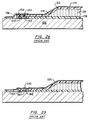
- FIG. 2a depicts a vacuum bag molding assembly wherein rows of vertically protruding pins 120 are affixed to a rigid mold member 122 and disposed in adjacent relation to the HC composite article 124 to be formed. As the upper composite skin 126 is laid over the honeycomb core 128, the pins 120 are caused to engage a peripheral portion 130 of the upper composite skin 126, i.e., pierce the composite fabric, to prevent lateral displacement thereof during the molding/compaction process.
- a bridging effect is thereby created in the upper composite skin 126, i.e., between the uppermost corner 132 of the honeycomb core 128 and the mating surface 134 of the lower composite skin 136, to react lateral compaction pressure and, consequently, prevent distortion of the honeycomb core 128.
- the protruding pins 120 are a source of high maintenance, i.e., requiring periodic cleaning and repair, pose a hazard to the operator, and create difficulties when sealing the vacuum bag 138 to the rigid mold member 122.
- the vacuum bag 138 must be sealed outboard of the protruding pins 120, thus requiring the additional step of disposing a protective elastomer strip 139 over the protruding pins 120 to prevent damage to the vacuum bag 138.
- FIG. 2b A similar approach is shown in Fig. 2b wherein a perforated or apertured metal strip 140 is substituted for the protruding pins 120.
- the peripheral portion 130 of the upper composite skin 126 is laid over the apertured metal strip 140 such that under compacting pressure the apertures 142 thereof capture or grip the peripheral portion 130 to prevent lateral displacement of the upper composite skin 126.
- This approach yields similar results to the above-described pinned configuration, however, laborious cleaning is required to remove excess resin from the apertures 142 prior to initiating the next cure cycle.
- the honeycomb core includes perforations in the cell walls to permit communication of pressure from one cell to an adjacent cell and ultimately to the entire back-side of the upper face plies. While this technique offers a unique solution, the cost associated with mold modifications and the laborious set-up associated with creating an closed internal system for internally pressurizing the HC composite article is fiscally disadvantageous.
- a method for making HC composite articles including the steps of: forming a honeycomb core having a core edge, placing a first composite skin in combination with a rigid mold member having a mold surface, mating the honeycomb core to the first composite skin thereby forming a mated subassembly, laying-up a second composite skin over the mated subassembly, which second composite skin is an uncured composite skin and which honeycomb core, first composite skin and second composite skin, in combination, define a composite lay-up; disposing a vacuum bag over the composite lay-up thereby forming a mold cavity between the mold surface and the vacuum bag, evacuating the mold cavity to urge the vacuum bag against the second composite skin for compacting the same against the mated subassembly, and curing the composite lay-up to form the honeycomb core composite article.
- the method is further characterized by the steps of: forming the first composite skin prior to the placing step so that the first composite skin is a precured composite skin having a restraint edge, disposing the second composite skin in combination with the mated subassembly such that a peripheral portion of the second composite skin extends beyond the restraint edge by a distance X and, furthermore, so that the peripheral portion is in superposed abutting engagement with the mold surface of the rigid mold member, and wherein the evacuating step causes the vacuum bag to effect engagement of the peripheral portion with the restraint edge and the mold surface for preventing lateral displacement of the second composite skin upon curing of the composite lay-up.
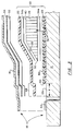
- Fig. 3 depicts an exploded partial cross-sectional view of a honeycomb core (HC) composite lay-up 10 disposed between a rigid mold member 12 and a vacuum bag 14 which, in combination, form a vacuum bag mold assembly 16.
- the composite lay-up 10 includes precured and uncured composite skins 20, 22, and a honeycomb core 24 disposed therebetween.
- the honeycomb core 24 may be any of the conventionally used open cellular honeycombs such as aluminum, phenolic or NOMEX® (NOMEX is a registered trademark of Hexcel Corp., Chatsworth, CA for an aramid fiber or fabric).
- NOMEX is a registered trademark of Hexcel Corp., Chatsworth, CA for an aramid fiber or fabric.
- a lightweight honeycomb core having a density of about 28.84 Kg/m 3 (1.8 lbs/ft 3 ) is preferred.
- honeycomb core is purchased in bulk and machined to the desired shape and size using Numerically Controlled (NC) machining apparatus. While the honeycomb core 24 is shown to have a ramped surface 26 to gradually transfer shear loads to the precured and uncured composite skins 20, 22, it will be understood that the teachings of the present invention are equally applicable to honeycomb cores having a right-angled configuration.
- the precured composite skin 20 is comprised of fiber reinforced resin matrix composite laminates having a fiber reinforcement such as graphite; aramide or fiberglass fibers disposed in a binding matrix such as epoxy, phenolic or other similar organic resinous material.
- a fiber reinforcement such as graphite
- aramide or fiberglass fibers disposed in a binding matrix such as epoxy, phenolic or other similar organic resinous material.
- two composite laminates having a total thickness of at least about .038 cm (.015 in) are laid-up in a mold assembly and cured to form a cured composite panel.
- Any conventional fabrication method, such as vacuum forming, resin transfer molding, or matched metal molding may be used to form and cure the composite panel.
- the preferred method utilizes a vacuum bag mold assembly wherein the same rigid mold member 12 employed for forming the HC composite lay-up is used for forming the precured composite skin 20.
- At least one end of the cured composite panel is trimmed, thus forming the precured first composite skin 20.
- the trimming operation also produces a restraint edge 30 having a right-angled configuration 30'. The utility of this construction will become evident when discussing the subsequent processing steps.
- the precured first composite skin 20 is then returned to the rigid mold member 12 and the honeycomb core 24 is mated therewith to form a mated subassembly 36 (see Fig. 4). Furthermore, the honeycomb core 24 is disposed in superposed relation with the precured composite skin 20 so that the restraint edge 30 extends beyond the edge 32 of the honeycomb core 24. The portion of the precured composite skin 20 extending beyond the core edge 32 defines an upwardly facing mating surface 38 which will, in subsequent steps, be disposed in combination with and bonded to the uncured composite skin 22.
- the mating step additionally includes the application of a bonding adhesive 34a to one or both of the mating surfaces, i.e., to either the honeycomb core 24 or the precured composite skin 20, for bonding the core to the precured composite skin 20.
- the bonding adhesive 34a is co-cured with the completed composite lay-up 10, i.e., concurrent with the curing step (cure cycle) described hereinbelow.
- the bonding operation may be performed prior to subsequent processing steps, e.g., as a independent operation requiring a unique cure cycle.
- the preferred bonding adhesive 34a is a film adhesive such as EA 9690 manufactured by Hysol Corp located in Pittsburgh, CA.
- the uncured composite skin 22 is comprised of one or more laminates of uncured preimpregnated fiber reinforced composite material having a fiber reinforcement such as graphite, aramide or fiberglass fibers disposed in a binding matrix such as epoxy, phenolic or other similar organic resinous material.
- a bonding adhesive 34b such as Hysol 9690 film adhesive, is first applied to the exposed upper surface 40 of the honeycomb core 24 in preparation for the lay-up of the uncured composite skin 22.
- the adhesive 34b facilitates the bonding of the uncured composite skin 22 to the honeycomb core 24, however, it will be appreciated that the uncured binding matrix, i.e., resin of the uncured composite skin 22, may adequately wet the honeycomb core surface during the cure cycle to effect a suitable bond, thereby eliminating the need for the bonding adhesive 34b.
- the uncured binding matrix i.e., resin of the uncured composite skin 22
- the uncured composite skin 22 is laid over the mated subassembly 36 and is precompacted using conventional debulking techniques to ensure intimate contact with the exposed upper honeycomb core surface 40 and the mating surface 38 of the precured composite skin 20. Furthermore, the uncured composite skin 22 is appropriately sized so as to permit a peripheral portion 44 thereof to extend beyond the restraint edge 30 of the precured composite skin 20. Moreover, the peripheral portion 44 is in superposed abutting engagement with the mold surface 12s of the rigid mold member 12 and extends a distance X beyond the restraint edge 30. Preferably, the peripheral portion 44 extends at least 1.9 cm (.75 in) beyond the edge 30 and, more preferably, about 2.5 cm (1 in) beyond the edge 30.
- the vacuum bag 14 is disposed over the completed composite lay-up 10 and sealed to the rigid mold member 12, or to itself, utilizing a conventional sealer strip 50 such as "Prestite" (Prestite is a brand name of a semi-adhesive compliant material produced by 3M located in St. Paul, MN for a semi-adhesive compliant).
- a separator or release film 52 and a breather ply 54 may be interposed between the uncured composite skin 22 and the vacuum bag 14.
- the separator film 52 facilitates release of the vacuum bag 14 after curing the composite lay-up 10 while the breather ply 54 facilitates the removal of air and volatiles from the uncured composite skin 22 during the cure cycle. Representative materials are specified in the below-described example.
- the use of the release film 52 and breather ply 54 are preferred, however, the composite lay-up 10 is minimally comprised of the honeycomb core 24, the precured composite skin 20, and the uncured composite skin 22.
- the completed vacuum bag molding assembly 16 shown in Fig. 4 forms a sealed mold cavity 60, i.e., between the rigid mold member 12 and the vacuum bag 14, which is in fluid communication with a vacuum pump 62.
- the vacuum pump 62 functions to evacuate the mold cavity 60 of gaseous fluids, i.e., air and volitales, and to create a pressure differential for urging the vacuum bag 14 against the uncured composite skin 22.
- the peripheral portion 44 of the uncured composite skin 22 is forced into engagement with the restraint edge 30 of the precured composite skin 20 and against the mold surface 12s.
- the vacuum bag molding assembly 16 is then placed in an autoclave oven (not shown) wherein the composite lay-up 10 is exposed to additional pressure and temperature for curing.
- the autoclave oven applies a pressure of about 3.72 x 10 7 -4.46 x 10 7 N/m 2 (25 - 30 lbs/in 2 ) to the lay-up and elevates the temperature thereof to about 121 - 232°C (250 - 450° F) degrees for a period of about 120 - 180 mins.
- the peripheral portion 44 of the uncured composite skin 22 engages the restraint edge 30 of the precured composite skin 20 so as to provide a mechanical interlock therebetween.
- the restraint edge 30 functions to inhibit the lateral displacement of the uncured composite skin 22 and, consequently, cause a bridging effect therein in the region overlaying the ramped honeycomb surface 26.
- the bridging effect functions to react the lateral component of pressure P applied by the vacuum bag 14.
- the contacting interface CI between the peripheral portion 44 and the mold surface 12s provides additional restraint toward the objective of inhibiting lateral displacement.
- the frictional force along the contacting interface CI augments the restraint capacity of the restraint edge 30. Accordingly, by inhibiting lateral displacement and, consequently, the catenary displacement of the uncured composite skin 22, shifting and/or distortion of the honeycomb core 24 is minimized.
- the cured composite lay-up may be trimmed along line T L to net dimension to form a honeycomb core composite article having a uniform thickness peripheral flange 70.
- the restraint edge 30 and the peripheral portion 44 are removed during this operation. Accordingly, the trimming operation removes the abrupt contour transition produced by the restraint edge 30 which enhances the strength of peripheral flange 70 for subsequent fastening and/or bonding operations.
- the restraint edge 30 and the mold surface 12s are tooling surfaces which are functionally equivalent to the prior art pinned and perforated metal strip configurations, however, it will be appreciated that the formation of these tooling surfaces is far less labor intensive.
- the restraint edge 30 is formed in conjunction with the manufacturing process and becomes and integral part of the finished HC composite article. Furthermore, the only additional step involves the formation of the precured composite skin 20. Insofar as it is advantageous to precure a composite laminate for the purposes of improving laminate quality and strength, the method of the present invention will have no adverse cost effect on the manufacturing process when such improved quality and strength are desired.
- the precured composite skin 20 may be formed under a pressure of 1.11 X 10 8 N/m 2 (75 lbs/in 2 ) to improve the fiber volume content, i.e., increase the fiber to resin ratio, and, consequently, the strength of the composite laminate.
- Such increased fiber volume is not achievable using conventional co-cure methods, i.e., wherein both composite skins are uncured before entering the autoclave oven, insofar as high compaction pressures cannot be transferred via the low density honeycomb core.
- the rigid mold member 12 With regard to fabricating the rigid mold member 12 to include the mold surface 12s, which is slightly enlarged for superpositioning of the peripheral portion 44, it will be appreciated that fabricating such an additional area surface is inconsequential in terms of time and labor.
- the hazards and periodic maintenance of the prior art tooling surfaces are entirely eliminated by the method of the present invention. That is, the present method does not introduce hazardous tooling surfaces, e.g., pins, or other tooling surfaces, e.g., apertures which require periodic cleaning.
- a honeycomb core (HC) composite article was fabricated using the teachings of the invention as follows.
- a sheet of 2.66 x 10 6 N/m 2 (1.8 lbs/ft 3 ) NOMEX® honeycomb core was machined to a thickness dimension of 3.0 cm (1.18 in), and a length and width dimension of 60.1 cm (24 in), respectively.
- the edges of the honeycomb core were beveled to form a 30° ramp angle about the entire periphery.
- the honeycomb core was then cleaned with alcohol and dried in an oven at 65.5° C (150° F) for a period of 120 minutes.
- a first composite skin was formed by cutting two plies of KEVLAR® fiber reinforced composite material (KEVLAR® is a registered trademark of E.I. du Pont de Nemours & Co. located in Wilmington, DE for an aromatic polyamide of high tensile strength) to a length and width dimension of 66.04 cm (26 in), respectively.
- the plies were sequentially laid in a rigid mold member of a vacuum bag molding assembly.
- a Fluorinated Ethylene-Propylene (FEP) separator film and a breather ply formed from a compliant porous material such as N-10 (the FEP film and N-10 ply were obtained from Airtech International located in Carson, CA) were respectively applied to the lay-up.
- FEP Fluorinated Ethylene-Propylene
- a vacuum bag was applied to the lay-up and sealed to the rigid mold member using Prestite adhesive.
- the completed vacuum bag molding assembly was then placed in an autoclave oven to cure the plies.
- the composite plies were step-cured for a period of 180 mins to a peak pressure and temperature of 1.11 X 10 8 N/m 2 (75 lbs/in 2 ) and 182.2°C (360° F), respectively.
- the lay-up resulted in a cured composite panel having a thickness dimension of .038 cm (.015 in).
- the cured composite panel was then trimmed about its periphery to form a precured composite skin having a restraint edge.
- the net size of the precured composite skin was approximately 63.5 cm (25 in) square.
- the precured composite skin was returned to the rigid mold member and a first layer of Hysol 9690 film adhesive was applied to the entire exposed surface.
- the prior-formed honeycomb core was then mated upon and centered over the precured composite skin so that the restraint edge extended approximately 2.54 cm (1 in) beyond the edge of the honeycomb core.
- a second layer of Hysol 9689 film adhesive was then applied to the exposed upper surface of the honeycomb core.
- An uncured composite skin comprising two plies of KEVLAR® material was laid over the mated subassembly, i.e., the honeycomb core and the precured composite skin, so that a peripheral portion of the uncured composite skin extended 2.54 cm (1 in) beyond the restraint edge of the precured composite skin.
- the uncured composite skin was debulked using conventional vacuum debulking apparatus for 5 minutes.
- An FEP separator film and an N-10 breather ply were sequentially laid over the uncured composite skin.
- a vacuum bag was then placed over the uncured composite skin and sealed to the rigid mold member, thereby forming a completed vacuum bag molding assembly.
- the mold cavity was evacuated so as to apply atmospheric pressure (full vacuum) via the vacuum bag to the underlying composite lay-up.
- the peripheral portion of the uncured composite skin was thereby simultaneously forced into engagement with the restraint edge of the precured composite skin and the mold surface of the rigid mold member, respectively.
- the vacuum bag molding assembly was then placing in an autoclave oven and step-cured as follows.
- the autoclave pressure was raised to 1.49 X 10 7 N/m 2 (10 lbs/in 2 ) and autoclave temperature was elevated to 93.3° C (200°F) for a first hold phase of 60 minutes.
- the autoclave pressure was gradually increased to 3.72 x 10 7 N/m 2 (25 lbs/in 2 ).
- the temperature was gradually raised to 182.2°C (360 °F) and held at a second hold phase (final cure phase) for 120 minutes.
- honeycomb core of the resultant composite article was found to be substantially distortion-free and accurately located relative to the composite skins.
- the above described method may be used alone or in combination with various core stabilization techniques such as those described in U.S. Patents 4,680,216 and 5,354,195. Furthermore, debulking operations may be performed between each of the above described lay-up steps to improve the efficacy of the resultant bonds.
Landscapes
- Engineering & Computer Science (AREA)
- Mechanical Engineering (AREA)
- Chemical & Material Sciences (AREA)
- Composite Materials (AREA)
- Textile Engineering (AREA)
- Casting Or Compression Moulding Of Plastics Or The Like (AREA)
- Laminated Bodies (AREA)
Abstract
Description
Claims (13)
- A method for making a honeycomb core composite article comprising the steps of:forming a honeycomb core (24) having a core edge (32);placing a first composite skin (20) in combination with a rigid mold member (12) having a mold surface (12s);mating said honeycomb core (24) to said first composite skin (20) thereby forming a mated subassembly (36) and so that an edge (30) of said first composite skin extends beyond said core edge (32);laying-up a second composite skin (22) over said mated subassembly (36), said second composite skin (22) being an uncured composite skin (22) so that said honeycomb core (24), said first composite skin (20) and said second composite skin, in combination, define a composite lay-up (10);disposing a vacuum bag (14) over said composite lay-up (10) thereby forming a mold cavity (60) between said mold surface (12s) and said vacuum bag (14);evacuating said mold cavity (60) to urge said vacuum bag (14) against said second composite skin (22) for compacting the same against said mated subassembly (36); andcuring said composite lay-up (10) to form the honeycomb core composite article;wherein the method is characterized by the steps of:forming the first composite skin (20) prior to said placing step so that said first composite skin is a precured composite skin (20) having a restraint edge (30);disposing said second composite skin (22) in combination with said mated subassembly (36) such that a peripheral portion (44) of the second composite skin (22) extends beyond said restraint edge (30) by a distance X and, furthermore, so that said peripheral portion (44) is in superposed abutting engagement with the mold surface (12s) of the rigid mold member (12): and whereinsaid evacuating step causes said vacuum bag (14) to effect engagement of said peripheral portion (44) with said restraint edge (30) and said mold surface (12s) for preventing lateral displacement of said second composite skin (22) upon curing of the composite lay-up (10).
- The method according to claim 1 further characterized in that said step of mating said honeycomb core (24) to said precured composite skin (20) includes the substep of applying a film adhesive (34a) between said honeycomb core (24) and said precured composite skin (20).
- The method according to claim 2 further characterized by the step of applying a bonding adhesive (34b) between said mated subassembly (36) and said uncured composite skin (22).
- The method according to claim 1 further characterized in that said uncured composite skin (22) is laid-up such that said distance X is greater than about 1.9 cm (.75 in).
- The method according to claim 1 further characterized by the step at trimming the cured honeycomb core composite article so that said restraint edge (30) and said peripheral portion (44) are removed.
- The method according to claim 1 further characterized in that said step of forming said precured composite skin (20) forms said precured composite skin (20) so that the thickness thereof is greater than about .038 cm (.015 in) and so that said restraint edge (30) defines a right angled configuration (30').
- The method according to claim 1 further characterized in that said step of forming said precured composite skin (20) includes the substeps of vacuum forming a lay-up of composite laminates in said rigid mold member (12), and trimming said vacuum-formed lay-up to form said restraint edge (30) of said precured composite skin (20).
- The method according to claim 1 further characterized by the step of applying a release film (52) in combination with said uncured composite skin (22).
- The method according to claim 8 further characterized by the step of applying a breather ply (54) in combination with said release film (52).
- A method for according to claim 4 further characterized in that said step of forming said precured composite skin (20) includes forming said precured composite skin (20) so that the thickness thereof is greater than about .038 cm (.015 in), and wherein the method is further characterized by the step of trimming the honeycomb core composite article so that said restraint edge (30) and said peripheral portion are removed.
- The method according to claim 10 further characterized in that said step of forming said precured composite skin (20) includes the substeps of vacuum forming a lay-up of composite laminates in said rigid mold member (12), and trimming said vacuum formed lay-up to form said restraint edge (30) of said precured composite skin (20).
- The method according to claim 10 further characterized by the step of applying a release film (52) in combination with said uncured composite skin (20).
- The method according to claim 10 further characterized by the step of applying a breather ply (54) in combination with said release film (52).
Applications Claiming Priority (1)
| Application Number | Priority Date | Filing Date | Title |
|---|---|---|---|
| PCT/US1995/001099 WO1996022878A1 (en) | 1995-01-27 | 1995-01-27 | Method for making honeycomb core composite articles |
Publications (2)
| Publication Number | Publication Date |
|---|---|
| EP0805747A1 EP0805747A1 (en) | 1997-11-12 |
| EP0805747B1 true EP0805747B1 (en) | 1998-12-02 |
Family
ID=22248575
Family Applications (1)
| Application Number | Title | Priority Date | Filing Date |
|---|---|---|---|
| EP95920367A Expired - Lifetime EP0805747B1 (en) | 1995-01-27 | 1995-01-27 | Method for making honeycomb core composite articles |
Country Status (11)
| Country | Link |
|---|---|
| US (1) | US5897739A (en) |
| EP (1) | EP0805747B1 (en) |
| JP (1) | JP3403201B2 (en) |
| KR (1) | KR19980701706A (en) |
| AU (1) | AU2584095A (en) |
| BR (1) | BR9510294A (en) |
| DE (1) | DE69506447T2 (en) |
| ES (1) | ES2124550T3 (en) |
| IL (1) | IL116783A (en) |
| TW (1) | TW421627B (en) |
| WO (1) | WO1996022878A1 (en) |
Cited By (1)
| Publication number | Priority date | Publication date | Assignee | Title |
|---|---|---|---|---|
| DE102009010621B3 (en) * | 2009-02-12 | 2010-12-02 | Mt Aerospace Ag | Method for stabilization of honeycomb core for sandwich composite structures made of fiber-reinforced composites, involves pre-fixing honeycomb core at open-cell side on manufacturing equipment with textured surface |
Families Citing this family (69)
| Publication number | Priority date | Publication date | Assignee | Title |
|---|---|---|---|---|
| IT1275957B1 (en) * | 1995-03-22 | 1997-10-24 | Viv Int Spa | PROCEDURE FOR PAINTING AND / OR DECORATING SEMI-FINISHED EXTRUDED OR DRAWN AND SIMILAR PRODUCTS |
| GB9620296D0 (en) | 1996-09-28 | 1996-11-13 | Carton Edge Ltd | Apparatus for mounting a cutting strip |
| GB9709011D0 (en) * | 1997-05-03 | 1997-06-25 | Advanced Composites Group Ltd | Improvements in or relating to pressure enhancers for use in the production of composite components |
| US6644954B2 (en) | 1997-05-03 | 2003-11-11 | Advanced Composites Group Ltd. | Pressure transmitters for use in the production of composite components |
| FR2763882B1 (en) * | 1997-05-29 | 1999-08-20 | Aerospatiale | ON-SITE REPAIR TOOLS OF A COMPOSITE STRUCTURE HAVING A DAMAGED AREA AND CORRESPONDING METHOD |
| US6179943B1 (en) * | 1997-07-30 | 2001-01-30 | The Boeing Company | Method for forming a composite acoustic panel |
| SE511321C2 (en) * | 1998-01-22 | 1999-09-13 | Sture Sjoeberg | Procedure for casting a body |
| IT1299073B1 (en) * | 1998-04-15 | 2000-02-07 | Viv Int Spa | PROCEDURE FOR THE PRODUCTION OF VARIETY PAINTED AND / OR DECORATED PRODUCTS USING THE TECHNIQUE OF TRANSFER FROM A COLOR SUPPORT |
| JP2003524666A (en) * | 1998-05-22 | 2003-08-19 | サイテック テクノロジイ コーポレーション | Product and core crash prevention methods |
| US6630093B1 (en) | 1999-08-21 | 2003-10-07 | Ronald D. Jones | Method for making freeform-fabricated core composite articles |
| JP4191343B2 (en) * | 1999-11-26 | 2008-12-03 | 本田技研工業株式会社 | Method for manufacturing honeycomb sandwich panel |
| WO2001041993A2 (en) * | 1999-12-07 | 2001-06-14 | The Boeing Company | Double bag vacuum infusion process and system for low cost, advanced composite fabrication |
| US6557702B1 (en) * | 2001-10-31 | 2003-05-06 | Skb Corporation | Golf club travel bag |
| US7226559B2 (en) * | 2000-12-08 | 2007-06-05 | Toyota Motor Sales, U.S.A., Inc. | Method for molding structures |
| JP2002264846A (en) * | 2001-03-06 | 2002-09-18 | Toray Ind Inc | FRP car panel |
| JP2002340280A (en) * | 2001-05-18 | 2002-11-27 | Jamco Corp | Vacuum insulation block |
| US6530330B2 (en) | 2001-06-29 | 2003-03-11 | Midcoast Aviation, Inc. | Lightweight aircraft table top |
| US6890401B2 (en) * | 2001-10-30 | 2005-05-10 | The Boeing Company | Liquid molded hollow cell core composite articles |
| US6739861B2 (en) | 2001-11-26 | 2004-05-25 | Sikorsky Aircraft Corporation | High pressure co-cure of lightweight core composite article utilizing a core having a plurality of protruding pins |
| DE10320791B4 (en) * | 2002-11-06 | 2016-09-15 | Airbus Operations Gmbh | Process for producing textile preforms from textile semi-finished products |
| NL1021860C2 (en) * | 2002-11-06 | 2004-05-07 | Stork Fokker Aesp Bv | Method for manufacturing a laminate. |
| US7048986B2 (en) * | 2003-06-12 | 2006-05-23 | Northrop Grumman Corporation | End gaps of filled honeycomb |
| US6830079B1 (en) * | 2003-08-27 | 2004-12-14 | General Electric Company | Integrated apparatus and method for filling porous composite preforms |
| US7138031B2 (en) * | 2003-09-09 | 2006-11-21 | The Boeing Company | Mandrel and method for manufacturing composite structures |
| US7294220B2 (en) * | 2003-10-16 | 2007-11-13 | Toyota Motor Sales, U.S.A., Inc. | Methods of stabilizing and/or sealing core material and stabilized and/or sealed core material |
| JP4016013B2 (en) * | 2004-05-10 | 2007-12-05 | 本田技研工業株式会社 | Method for producing laminated molded product |
| US8052831B2 (en) * | 2005-02-02 | 2011-11-08 | The Boeing Company | Low temperature, vacuum cure fabrication process for large, honeycomb core stiffened composite structures |
| US7416401B2 (en) * | 2005-06-13 | 2008-08-26 | The Boeing Company | Lightweight composite fairing bar and method for manufacturing the same |
| JP2007098819A (en) * | 2005-10-06 | 2007-04-19 | Mitsubishi Rayon Co Ltd | Method for manufacturing sandwich panel |
| DE102006031336B4 (en) | 2006-07-06 | 2010-08-05 | Airbus Deutschland Gmbh | Method for producing a fiber composite component in the aerospace industry |
| DE102006031325B4 (en) * | 2006-07-06 | 2010-07-01 | Airbus Deutschland Gmbh | Method for producing a fiber composite component for aerospace applications |
| EP1882573B1 (en) * | 2006-07-27 | 2010-09-08 | GEKE Equitec GmbH | Vulcanizing method for multilayer components having a large surface |
| GB0702781D0 (en) * | 2007-02-13 | 2007-03-21 | Airbus Uk Ltd | Method of processing a composite material |
| US20080277531A1 (en) * | 2007-05-11 | 2008-11-13 | The Boeing Company | Hybrid Composite Panel Systems and Methods |
| FR2921295A1 (en) * | 2007-09-24 | 2009-03-27 | Airbus France Sas | DEVICE FOR MANUFACTURING A COMPOSITE MATERIAL PART INTEGRATING A DRAINAGE SYSTEM |
| US8403624B2 (en) * | 2007-12-12 | 2013-03-26 | General Electric Company | Composite containment casings having an integral fragment catcher |
| US8371009B2 (en) * | 2007-12-12 | 2013-02-12 | General Electric Company | Methods for repairing composite containment casings |
| GB0805268D0 (en) * | 2008-03-25 | 2008-04-30 | Airbus Uk Ltd | Composite joint protection |
| FR2945573B1 (en) * | 2009-05-12 | 2014-06-27 | Snecma | CHUCK FOR MANUFACTURING A COMPOSITE MATERIAL CASING FOR A GAS TURBINE. |
| EP2266784A1 (en) * | 2009-06-22 | 2010-12-29 | Eurocopter Deutschland GmbH | Method for producing a sandwich component having a honeycomb core |
| ES2423186T3 (en) * | 2009-08-20 | 2013-09-18 | Siemens Aktiengesellschaft | Fiber reinforced plastic structure and method to produce fiber reinforced plastic structure |
| US8491743B2 (en) * | 2009-12-15 | 2013-07-23 | The Boeing Company | Composite ply stabilizing method |
| CN102753338B (en) * | 2010-02-05 | 2015-12-02 | 贝尔直升机泰克斯特龙公司 | Manufacture the method for strengthening core structure |
| US10369772B2 (en) | 2012-07-10 | 2019-08-06 | Textron Innovations Inc. | Method of making core-stiffened structure |
| GB2478312B (en) * | 2010-03-02 | 2012-08-22 | Gkn Aerospace Services Ltd | Seamless acoustic liner |
| US20120199292A1 (en) * | 2011-02-03 | 2012-08-09 | Sikorsky Aircraft Corporation | Ply locking for honeycomb panels |
| GB201200912D0 (en) * | 2012-01-19 | 2012-02-29 | Airbus Operations Ltd | Fastener receptacle strip |
| EP3089876B1 (en) * | 2013-12-20 | 2020-05-06 | United Technologies Corporation | Enhanced volatile removal for composite layup |
| US10357925B2 (en) | 2013-12-20 | 2019-07-23 | United Technologies Corporation | Enhanced volatile removal for composite layup |
| JP6199191B2 (en) * | 2014-01-10 | 2017-09-20 | 公益財団法人鉄道総合技術研究所 | Manufacturing method of bonding material |
| RU2559446C1 (en) * | 2014-03-05 | 2015-08-10 | Открытое акционерное общество "Обнинское научно-производственное предприятие "Технология" | Manufacturing method of three-layered panel from composite material |
| RU2564952C1 (en) * | 2014-04-14 | 2015-10-10 | Акционерное общество "Обнинское научно-производственное предприятие "Технология" им. А.Г. Ромашина" | Method to manufacture three-layer panel from composite material |
| GB201514579D0 (en) | 2015-08-17 | 2015-09-30 | Invibio Device Component Mfg Ltd | A device |
| CN107627625B (en) * | 2016-07-18 | 2021-04-09 | 深圳光启高等理工研究院 | The negative mold forming method of composite material parts |
| RU2685218C1 (en) * | 2017-12-18 | 2019-04-16 | Общество с ограниченной ответственностью "Тулпар Интерьер Групп" | Method for producing curvilinear three-layer composite panels |
| US11007724B2 (en) * | 2018-08-08 | 2021-05-18 | Textron Innovations Inc. | Skin-to-core bond line mapping system and method |
| CN111745999A (en) * | 2020-06-12 | 2020-10-09 | 陕西飞机工业(集团)有限公司 | Appearance processing method of composite material part with R corners |
| CN112223783A (en) * | 2020-09-22 | 2021-01-15 | 肇庆市海特复合材料技术研究院 | Forming die and preparation method of lower frame of composite material battery pack |
| CN112454938A (en) * | 2020-09-30 | 2021-03-09 | 成都飞机工业(集团)有限责任公司 | Forming method of carbon fiber honeycomb sandwich composite material member |
| KR102369172B1 (en) * | 2021-05-11 | 2022-03-03 | 한국항공우주산업 주식회사 | Composite material molding apparatus for aircraft |
| US11413795B1 (en) * | 2021-08-12 | 2022-08-16 | King Abdulaziz University | Method of making composite from green material |
| KR102395954B1 (en) * | 2021-11-01 | 2022-05-12 | 덕양산업 주식회사 | Interior material manufacturing device using vacuum pressure |
| CN115302812B (en) * | 2022-06-29 | 2025-04-08 | 中航西安飞机工业集团股份有限公司 | Packaging method for manufacturing large-curvature composite material part by co-cementing process |
| CN115350976A (en) * | 2022-07-21 | 2022-11-18 | 成都飞机工业(集团)有限责任公司 | Aramid fiber paper honeycomb core side pressure resistance pretreatment method and aramid fiber paper honeycomb core |
| US12515436B2 (en) * | 2023-05-01 | 2026-01-06 | Embraer S.A. | Honeycomb core stabilization for composite parts |
| US12325217B2 (en) * | 2023-05-13 | 2025-06-10 | The Boeing Company | Combined material honeycomb core |
| CN116945648B (en) * | 2023-07-03 | 2026-04-14 | 成都飞机工业(集团)有限责任公司 | Forming method of large-core lattice honeycomb sandwich composite material part with curvature |
| CN117698165A (en) * | 2024-01-15 | 2024-03-15 | 江西信达航科新材料科技有限公司 | Unmanned aerial vehicle thin skin low density foam intermediate layer combined material structure |
| CN119795618B (en) * | 2024-12-19 | 2025-10-17 | 航天海鹰(镇江)特种材料有限公司 | A method for preventing the thin-walled skin of a honeycomb sandwich composite material from collapsing |
Family Cites Families (13)
| Publication number | Priority date | Publication date | Assignee | Title |
|---|---|---|---|---|
| FR2190617B1 (en) * | 1972-06-30 | 1976-04-30 | Nippon Sheet Glass Co Ltd | |
| US4053667A (en) * | 1974-09-09 | 1977-10-11 | Lockheed Aircraft Corporation | Stiffened structural laminate and method of molding laminate with stiffener beads |
| FR2383769A1 (en) * | 1977-03-17 | 1978-10-13 | Chrysler France | Moulds with dowels to positively locate inserts - to inhibit displacement and to integrate insert bending or boring with moulding |
| US4542056A (en) * | 1983-08-26 | 1985-09-17 | The Boeing Company | Composite structure having conductive surfaces |
| US4680216A (en) * | 1984-09-04 | 1987-07-14 | United Technologies Corporation | Method for stabilizing thick honeycomb core composite articles |
| US4816106A (en) * | 1984-12-13 | 1989-03-28 | Aeritalia Saipa - Gruppo Velivoli Da Trasporto | Method for the controlled curing of composites |
| US4826106A (en) * | 1987-02-18 | 1989-05-02 | Grumman Aerospace Corporation | Advanced composite aircraft cowl |
| US4869770A (en) * | 1987-12-03 | 1989-09-26 | The Boeing Company | Method and apparatus for laminating composite materials |
| US4942013A (en) * | 1989-03-27 | 1990-07-17 | Mcdonnell Douglas Corporation | Vacuum resin impregnation process |
| US5242651A (en) * | 1990-07-25 | 1993-09-07 | Vought Aircraft Company | Pressure balanced processing of composite structures |
| US5281388A (en) * | 1992-03-20 | 1994-01-25 | Mcdonnell Douglas Corporation | Resin impregnation process for producing a resin-fiber composite |
| US5261993A (en) * | 1992-06-08 | 1993-11-16 | Airtech International Inc. | Means for bonding shaped parts of composites or other materials |
| US5354195A (en) * | 1992-12-23 | 1994-10-11 | United Technologies Corporation | Composite molding apparatus for high pressure co-cure molding of lightweight honeycomb core composite articles having ramped surfaces utilizing low density, stabilized ramped honeycomb cores |
-
1995
- 1995-01-27 AU AU25840/95A patent/AU2584095A/en not_active Abandoned
- 1995-01-27 EP EP95920367A patent/EP0805747B1/en not_active Expired - Lifetime
- 1995-01-27 US US08/612,948 patent/US5897739A/en not_active Expired - Fee Related
- 1995-01-27 ES ES95920367T patent/ES2124550T3/en not_active Expired - Lifetime
- 1995-01-27 BR BR9510294A patent/BR9510294A/en not_active Application Discontinuation
- 1995-01-27 WO PCT/US1995/001099 patent/WO1996022878A1/en not_active Ceased
- 1995-01-27 KR KR1019970705102A patent/KR19980701706A/en not_active Withdrawn
- 1995-01-27 DE DE69506447T patent/DE69506447T2/en not_active Expired - Fee Related
- 1995-01-27 JP JP52282896A patent/JP3403201B2/en not_active Expired - Fee Related
-
1996
- 1996-01-16 IL IL11678396A patent/IL116783A/en active IP Right Grant
- 1996-01-20 TW TW085100675A patent/TW421627B/en not_active IP Right Cessation
Cited By (1)
| Publication number | Priority date | Publication date | Assignee | Title |
|---|---|---|---|---|
| DE102009010621B3 (en) * | 2009-02-12 | 2010-12-02 | Mt Aerospace Ag | Method for stabilization of honeycomb core for sandwich composite structures made of fiber-reinforced composites, involves pre-fixing honeycomb core at open-cell side on manufacturing equipment with textured surface |
Also Published As
| Publication number | Publication date |
|---|---|
| KR19980701706A (en) | 1998-06-25 |
| EP0805747A1 (en) | 1997-11-12 |
| IL116783A0 (en) | 1996-05-14 |
| DE69506447T2 (en) | 1999-07-01 |
| BR9510294A (en) | 1997-11-11 |
| JPH10512820A (en) | 1998-12-08 |
| AU2584095A (en) | 1996-08-14 |
| DE69506447D1 (en) | 1999-01-14 |
| TW421627B (en) | 2001-02-11 |
| ES2124550T3 (en) | 1999-02-01 |
| IL116783A (en) | 2000-07-26 |
| WO1996022878A1 (en) | 1996-08-01 |
| JP3403201B2 (en) | 2003-05-06 |
| US5897739A (en) | 1999-04-27 |
Similar Documents
| Publication | Publication Date | Title |
|---|---|---|
| US5897739A (en) | Method for making honeycomb core composite articles | |
| US4963215A (en) | Method for debulking precured thermoplastic composite laminae | |
| EP0904929B1 (en) | Method for forming a caul plate during moulding of a part | |
| EP1134070B1 (en) | Process for manufacturing pre-cured parts of composite material with green-applied stiffeners | |
| KR100286153B1 (en) | Complex molding apparatus, high pressure co-curing molding method using the same, and honeycomb core molded product manufactured therefrom | |
| US4680216A (en) | Method for stabilizing thick honeycomb core composite articles | |
| EP1005978B1 (en) | Methods of forming honeycomb sandwich composite panels | |
| US20080210372A1 (en) | Composite article debulking process | |
| EP0318867A2 (en) | Method and apparatus for laminating composite materials | |
| EP2569142B1 (en) | Method of making a composite sandwich structure | |
| CN105904740A (en) | Integral manufacturing method of composite material light continuous fiber grid | |
| US20030098520A1 (en) | High pressure co-cure of lightweight core composite article utilizing a core having a plurality of protruding pins | |
| EP2070694B1 (en) | Composite panel and method of manufacturing the same | |
| JPH04301410A (en) | Manufacture of composite material product having complicate form | |
| US20040140049A1 (en) | Method of manufacturing a hollow section, grid stiffened panel | |
| EP1687131B1 (en) | Breather sheet for composite curing and method of its assembly | |
| US20140360665A1 (en) | Reflector manufactured using multiple use precision extractable tooling | |
| JP4328579B2 (en) | Method for manufacturing honeycomb sandwich panel | |
| EP0319895A2 (en) | Method for debulking partially precured thermoplastic composite laminae | |
| CA2211556A1 (en) | Method for making honeycomb core composite articles | |
| US6565690B1 (en) | Process for manufacturing structures of composite material | |
| JP4464208B2 (en) | Method for manufacturing honeycomb sandwich panel | |
| EP4289604B1 (en) | Composite manufacturing method | |
| US20030051434A1 (en) | Composite structure and method for constructing same | |
| JPH0611522B2 (en) | Honeycomb core structure and manufacturing method thereof |
Legal Events
| Date | Code | Title | Description |
|---|---|---|---|
| PUAI | Public reference made under article 153(3) epc to a published international application that has entered the european phase |
Free format text: ORIGINAL CODE: 0009012 |
|
| 17P | Request for examination filed |
Effective date: 19970728 |
|
| AK | Designated contracting states |
Kind code of ref document: A1 Designated state(s): DE ES FR GB IT |
|
| GRAG | Despatch of communication of intention to grant |
Free format text: ORIGINAL CODE: EPIDOS AGRA |
|
| 17Q | First examination report despatched |
Effective date: 19980414 |
|
| GRAG | Despatch of communication of intention to grant |
Free format text: ORIGINAL CODE: EPIDOS AGRA |
|
| GRAH | Despatch of communication of intention to grant a patent |
Free format text: ORIGINAL CODE: EPIDOS IGRA |
|
| GRAH | Despatch of communication of intention to grant a patent |
Free format text: ORIGINAL CODE: EPIDOS IGRA |
|
| GRAA | (expected) grant |
Free format text: ORIGINAL CODE: 0009210 |
|
| AK | Designated contracting states |
Kind code of ref document: B1 Designated state(s): DE ES FR GB IT |
|
| REF | Corresponds to: |
Ref document number: 69506447 Country of ref document: DE Date of ref document: 19990114 |
|
| REG | Reference to a national code |
Ref country code: ES Ref legal event code: FG2A Ref document number: 2124550 Country of ref document: ES Kind code of ref document: T3 |
|
| ET | Fr: translation filed | ||
| PLBE | No opposition filed within time limit |
Free format text: ORIGINAL CODE: 0009261 |
|
| STAA | Information on the status of an ep patent application or granted ep patent |
Free format text: STATUS: NO OPPOSITION FILED WITHIN TIME LIMIT |
|
| 26N | No opposition filed | ||
| PGFP | Annual fee paid to national office [announced via postgrant information from national office to epo] |
Ref country code: ES Payment date: 20000113 Year of fee payment: 6 |
|
| PG25 | Lapsed in a contracting state [announced via postgrant information from national office to epo] |
Ref country code: ES Free format text: LAPSE BECAUSE OF NON-PAYMENT OF DUE FEES Effective date: 20010129 |
|
| REG | Reference to a national code |
Ref country code: GB Ref legal event code: IF02 |
|
| REG | Reference to a national code |
Ref country code: ES Ref legal event code: FD2A Effective date: 20020916 |
|
| PGFP | Annual fee paid to national office [announced via postgrant information from national office to epo] |
Ref country code: FR Payment date: 20041209 Year of fee payment: 11 |
|
| PGFP | Annual fee paid to national office [announced via postgrant information from national office to epo] |
Ref country code: GB Payment date: 20041213 Year of fee payment: 11 |
|
| PGFP | Annual fee paid to national office [announced via postgrant information from national office to epo] |
Ref country code: DE Payment date: 20041214 Year of fee payment: 11 |
|
| PG25 | Lapsed in a contracting state [announced via postgrant information from national office to epo] |
Ref country code: IT Free format text: LAPSE BECAUSE OF NON-PAYMENT OF DUE FEES;WARNING: LAPSES OF ITALIAN PATENTS WITH EFFECTIVE DATE BEFORE 2007 MAY HAVE OCCURRED AT ANY TIME BEFORE 2007. THE CORRECT EFFECTIVE DATE MAY BE DIFFERENT FROM THE ONE RECORDED. Effective date: 20050127 |
|
| PG25 | Lapsed in a contracting state [announced via postgrant information from national office to epo] |
Ref country code: GB Free format text: LAPSE BECAUSE OF NON-PAYMENT OF DUE FEES Effective date: 20060127 |
|
| PG25 | Lapsed in a contracting state [announced via postgrant information from national office to epo] |
Ref country code: FR Free format text: LAPSE BECAUSE OF NON-PAYMENT OF DUE FEES Effective date: 20060131 |
|
| PG25 | Lapsed in a contracting state [announced via postgrant information from national office to epo] |
Ref country code: DE Free format text: LAPSE BECAUSE OF NON-PAYMENT OF DUE FEES Effective date: 20060801 |
|
| GBPC | Gb: european patent ceased through non-payment of renewal fee |
Effective date: 20060127 |
|
| REG | Reference to a national code |
Ref country code: FR Ref legal event code: ST Effective date: 20060929 |