EP0805301B1 - Insert and procedure for the renovation of leaking pipe walls using such an insert - Google Patents
Insert and procedure for the renovation of leaking pipe walls using such an insert Download PDFInfo
- Publication number
- EP0805301B1 EP0805301B1 EP97890082A EP97890082A EP0805301B1 EP 0805301 B1 EP0805301 B1 EP 0805301B1 EP 97890082 A EP97890082 A EP 97890082A EP 97890082 A EP97890082 A EP 97890082A EP 0805301 B1 EP0805301 B1 EP 0805301B1
- Authority
- EP
- European Patent Office
- Prior art keywords
- insert
- compact layer
- laminate
- layer
- interior wall
- Prior art date
- Legal status (The legal status is an assumption and is not a legal conclusion. Google has not performed a legal analysis and makes no representation as to the accuracy of the status listed.)
- Expired - Lifetime
Links
Images
Classifications
-
- E—FIXED CONSTRUCTIONS
- E03—WATER SUPPLY; SEWERAGE
- E03F—SEWERS; CESSPOOLS
- E03F3/00—Sewer pipe-line systems
- E03F3/06—Methods of, or installations for, laying sewer pipes
-
- B—PERFORMING OPERATIONS; TRANSPORTING
- B29—WORKING OF PLASTICS; WORKING OF SUBSTANCES IN A PLASTIC STATE IN GENERAL
- B29C—SHAPING OR JOINING OF PLASTICS; SHAPING OF MATERIAL IN A PLASTIC STATE, NOT OTHERWISE PROVIDED FOR; AFTER-TREATMENT OF THE SHAPED PRODUCTS, e.g. REPAIRING
- B29C65/00—Joining or sealing of preformed parts, e.g. welding of plastics materials; Apparatus therefor
- B29C65/02—Joining or sealing of preformed parts, e.g. welding of plastics materials; Apparatus therefor by heating, with or without pressure
- B29C65/34—Joining or sealing of preformed parts, e.g. welding of plastics materials; Apparatus therefor by heating, with or without pressure using heated elements which remain in the joint, e.g. "verlorenes Schweisselement"
- B29C65/3404—Joining or sealing of preformed parts, e.g. welding of plastics materials; Apparatus therefor by heating, with or without pressure using heated elements which remain in the joint, e.g. "verlorenes Schweisselement" characterised by the type of heated elements which remain in the joint
- B29C65/342—Joining or sealing of preformed parts, e.g. welding of plastics materials; Apparatus therefor by heating, with or without pressure using heated elements which remain in the joint, e.g. "verlorenes Schweisselement" characterised by the type of heated elements which remain in the joint comprising at least a single wire, e.g. in the form of a winding
-
- B—PERFORMING OPERATIONS; TRANSPORTING
- B29—WORKING OF PLASTICS; WORKING OF SUBSTANCES IN A PLASTIC STATE IN GENERAL
- B29C—SHAPING OR JOINING OF PLASTICS; SHAPING OF MATERIAL IN A PLASTIC STATE, NOT OTHERWISE PROVIDED FOR; AFTER-TREATMENT OF THE SHAPED PRODUCTS, e.g. REPAIRING
- B29C66/00—General aspects of processes or apparatus for joining preformed parts
- B29C66/70—General aspects of processes or apparatus for joining preformed parts characterised by the composition, physical properties or the structure of the material of the parts to be joined; Joining with non-plastics material
- B29C66/73—General aspects of processes or apparatus for joining preformed parts characterised by the composition, physical properties or the structure of the material of the parts to be joined; Joining with non-plastics material characterised by the intensive physical properties of the material of the parts to be joined, by the optical properties of the material of the parts to be joined, by the extensive physical properties of the parts to be joined, by the state of the material of the parts to be joined or by the material of the parts to be joined being a thermoplastic or a thermoset
- B29C66/739—General aspects of processes or apparatus for joining preformed parts characterised by the composition, physical properties or the structure of the material of the parts to be joined; Joining with non-plastics material characterised by the intensive physical properties of the material of the parts to be joined, by the optical properties of the material of the parts to be joined, by the extensive physical properties of the parts to be joined, by the state of the material of the parts to be joined or by the material of the parts to be joined being a thermoplastic or a thermoset characterised by the material of the parts to be joined being a thermoplastic or a thermoset
- B29C66/7392—General aspects of processes or apparatus for joining preformed parts characterised by the composition, physical properties or the structure of the material of the parts to be joined; Joining with non-plastics material characterised by the intensive physical properties of the material of the parts to be joined, by the optical properties of the material of the parts to be joined, by the extensive physical properties of the parts to be joined, by the state of the material of the parts to be joined or by the material of the parts to be joined being a thermoplastic or a thermoset characterised by the material of the parts to be joined being a thermoplastic or a thermoset characterised by the material of at least one of the parts being a thermoplastic
-
- F—MECHANICAL ENGINEERING; LIGHTING; HEATING; WEAPONS; BLASTING
- F16—ENGINEERING ELEMENTS AND UNITS; GENERAL MEASURES FOR PRODUCING AND MAINTAINING EFFECTIVE FUNCTIONING OF MACHINES OR INSTALLATIONS; THERMAL INSULATION IN GENERAL
- F16L—PIPES; JOINTS OR FITTINGS FOR PIPES; SUPPORTS FOR PIPES, CABLES OR PROTECTIVE TUBING; MEANS FOR THERMAL INSULATION IN GENERAL
- F16L55/00—Devices or appurtenances for use in, or in connection with, pipes or pipe systems
- F16L55/16—Devices for covering leaks in pipes or hoses, e.g. hose-menders
- F16L55/179—Devices for covering leaks in pipes or hoses, e.g. hose-menders specially adapted for bends, branch units, branching pipes or the like
-
- B—PERFORMING OPERATIONS; TRANSPORTING
- B29—WORKING OF PLASTICS; WORKING OF SUBSTANCES IN A PLASTIC STATE IN GENERAL
- B29C—SHAPING OR JOINING OF PLASTICS; SHAPING OF MATERIAL IN A PLASTIC STATE, NOT OTHERWISE PROVIDED FOR; AFTER-TREATMENT OF THE SHAPED PRODUCTS, e.g. REPAIRING
- B29C65/00—Joining or sealing of preformed parts, e.g. welding of plastics materials; Apparatus therefor
- B29C65/02—Joining or sealing of preformed parts, e.g. welding of plastics materials; Apparatus therefor by heating, with or without pressure
- B29C65/34—Joining or sealing of preformed parts, e.g. welding of plastics materials; Apparatus therefor by heating, with or without pressure using heated elements which remain in the joint, e.g. "verlorenes Schweisselement"
- B29C65/3472—Joining or sealing of preformed parts, e.g. welding of plastics materials; Apparatus therefor by heating, with or without pressure using heated elements which remain in the joint, e.g. "verlorenes Schweisselement" characterised by the composition of the heated elements which remain in the joint
- B29C65/3476—Joining or sealing of preformed parts, e.g. welding of plastics materials; Apparatus therefor by heating, with or without pressure using heated elements which remain in the joint, e.g. "verlorenes Schweisselement" characterised by the composition of the heated elements which remain in the joint being metallic
-
- B—PERFORMING OPERATIONS; TRANSPORTING
- B29—WORKING OF PLASTICS; WORKING OF SUBSTANCES IN A PLASTIC STATE IN GENERAL
- B29C—SHAPING OR JOINING OF PLASTICS; SHAPING OF MATERIAL IN A PLASTIC STATE, NOT OTHERWISE PROVIDED FOR; AFTER-TREATMENT OF THE SHAPED PRODUCTS, e.g. REPAIRING
- B29C66/00—General aspects of processes or apparatus for joining preformed parts
- B29C66/70—General aspects of processes or apparatus for joining preformed parts characterised by the composition, physical properties or the structure of the material of the parts to be joined; Joining with non-plastics material
- B29C66/71—General aspects of processes or apparatus for joining preformed parts characterised by the composition, physical properties or the structure of the material of the parts to be joined; Joining with non-plastics material characterised by the composition of the plastics material of the parts to be joined
-
- E—FIXED CONSTRUCTIONS
- E03—WATER SUPPLY; SEWERAGE
- E03F—SEWERS; CESSPOOLS
- E03F3/00—Sewer pipe-line systems
- E03F3/06—Methods of, or installations for, laying sewer pipes
- E03F2003/065—Refurbishing of sewer pipes, e.g. by coating, lining
Definitions
- the invention relates to an insert part, which is used for the production of a connection between the plastic inner wall of a pipeline, a channel or the like. and one with a plastic adhesive, especially one by applying heat curable polyester resin, soaked laminate is arranged. It also affects Invention a method for the rehabilitation of the leaky walls of pipes, channels or the like.
- the inner wall of a plastic material, preferably of polyethylene consists of or is provided with an inliner made of plastic, preferably of polyethylene, being soaked in a polyester resin on the inner wall parts to be renovated Laminate applied and allowed to cure by exposure to heat radiation.
- the area to be renovated Channel section a tubular, with a by exposure to heat radiation curing polymer resin impregnated laminate applied under pressure and in subsequently cured by exposure to UV radiation.
- the curing takes place hiebei within minutes, the laminate adapts to the surface shape of the adapting wall areas and after stiffening firmly on this surface is applied.
- an epoxy resin are applied, which is a solid Ensures and a connection between these edge areas and the inner wall Liquid penetration between the inner wall and the laminate with certainty prevented.
- the object of the present invention is to overcome this disadvantage avoid and the establishment of a solid, liquid-tight connection between the plastic inner wall of a pipe, a channel or the like. and one with a plastic adhesive, especially one that can be hardened by applying heat Polyester resin to allow soaked laminate, being a common, tubular Laminate can be used, the end areas of which none before insertion Processing required.
- the invention proposes one of Laminate separate insert part, which is a compact layer from one Plastic from which the inner wall is made, plastic of the same type and one with it compact layer connected, in particular laminated onto the compact layer has porous layer, the compact layer with the inner wall and the porous Layer with the laminate, preferably by heat.
- the compact layer of the insert part is welded to the heat Plastic existing inner wall of the pipeline, the channel or the like. and the porous Layer is over the plastic adhesive, preferably that by applying heat curable polyester resin, firmly with the laminate soaked with this plastic adhesive glued, so that a good connection between the inner wall and the laminate is ensured.
- the compact layer also consists of polyethylene.
- a weld of the Polyethylene material can be achieved in this case without difficulty.
- the compact layer expediently has a wall thickness between 1 mm and 4 mm, preferably of about 2 mm. With such a wall thickness, the compact layer on the one hand has sufficient strength, but can on the other hand still good on the inner wall of the pipeline, the channel or the like. nestle, too if it is uneven.
- the porous layer suitably consists of a fleece, preferably of a Polyethylene fleece can therefore be made of the same material as the compact layer be formed, whereby a secure connection by lamination to the compact Layer is guaranteed.
- the laminate which is connected to the porous layer is soaked with a plastic adhesive, via which the connection with the porous Layer takes place.
- porous Layer with a plastic adhesive especially one with heat curable polyester resin, soak so that a perfect bond ensures is.
- the compact layer with the inner wall of the pipeline welded for which purpose the plastic of this inner wall and the compact layer Heat supply must be pasted.
- the compact layer with electrical connectable to a power source Resistance heating wires is provided. Just to warm each other up to achieve contacting surfaces for the purpose of welding them, it is advantageous the electrical resistance heating wires on the surface of the compact layer to arrange, preferably to partially embed in this surface.
- the supply of heat is preferably carried out in a manner known per se caused by a heat radiation source, in particular a UV lamp and in addition the electrical resistance heating wires are connected to voltage so that both perfect static and pressure-tight connection between the inner wall and the Inliner and the compact layer of the insert as well as between the laminate and the porous layer of the insert takes place.
- a heat radiation source in particular a UV lamp
- the electrical resistance heating wires are connected to voltage so that both perfect static and pressure-tight connection between the inner wall and the Inliner and the compact layer of the insert as well as between the laminate and the porous layer of the insert takes place.
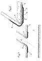
- Fig. 1 shows a channel branch from a main channel, in which Area of the junction is the location to be renovated, and Fig. 2 represents in larger Scale represents an insert part according to the invention.
- a duct junction 2 opens into the main duct 1.
- the main duct 1 is included a liner 3 made of polyethylene lined.
- the leak in shape a column 4 is in a manner known per se by a soaked with polyester resin Laminate 5 refurbished, which is applied under pressure, the polyester resin is allowed to cure by the action of heat, in particular by UV radiation. On in this way, a firm and liquid-tight connection can be made between the laminate 5 and the duct junction 2 can be achieved, but not with the inliner 3 Polyethylene, since polyethylene does not bond with the laminate 5 using the polyester resin can stick together.
- This Insert part 6 as can be seen from FIG. 2, consists of two layers, namely one compact layer 7 made of polyethylene and a porous layer 8 in the form of a Polyethylene fleece, which is laminated onto the compact layer 7.
- the polyethylene fleece 8 is impregnated with a polyester resin.
- the insert part 6 becomes a system before the laminate 5 is applied to the inliner 3 brought in such a way that the resistance heating wires 9 touch the inliner 3. Subsequently the laminate 5 is applied to the porous layer 8 of the insert 6.
- This Work is carried out using a sewer robot, which also has a UV lamp is arranged.
- the sewer robot has electrical connections for the Feeding of the resistance heating wires 9.
Landscapes
- Engineering & Computer Science (AREA)
- Mechanical Engineering (AREA)
- General Engineering & Computer Science (AREA)
- Health & Medical Sciences (AREA)
- Life Sciences & Earth Sciences (AREA)
- Hydrology & Water Resources (AREA)
- Public Health (AREA)
- Water Supply & Treatment (AREA)
- Laminated Bodies (AREA)
- Lining Or Joining Of Plastics Or The Like (AREA)
- Joining Of Building Structures In Genera (AREA)
- Extrusion Moulding Of Plastics Or The Like (AREA)
Abstract
Description
Die Erfindung betrifft einen Einsatzteil, der für die Herstellung einer Verbindung zwischen der aus Kunststoff bestehenden Innenwand einer Rohrleitung, eines Kanales od.dgl. und einem mit einem Kunststoffkleber, insbesondere einem durch Wärmezufuhr aushärtbaren Polyesterharz, getränkten Laminat angeordnet wird. Femer betrifft die Erfindung ein Verfahren zum Sanieren der undichten Wände von Rohrleitungen, Kanälen od.dgl., deren Innenwand aus einem Kunststoffmaterial, vorzugsweise aus Polyäthylen besteht oder mit einem Inliner aus Kunststoff, vorzugsweise aus Polyäthylen, versehen ist, wobei auf die zu sanierenden Innenwandteile ein mit einem Polyesterharz getränktes Laminat aufgebracht und durch Einwirken einer Wärmestrahlung aushärten gelassen wird.The invention relates to an insert part, which is used for the production of a connection between the plastic inner wall of a pipeline, a channel or the like. and one with a plastic adhesive, especially one by applying heat curable polyester resin, soaked laminate is arranged. It also affects Invention a method for the rehabilitation of the leaky walls of pipes, channels or the like., The inner wall of a plastic material, preferably of polyethylene consists of or is provided with an inliner made of plastic, preferably of polyethylene, being soaked in a polyester resin on the inner wall parts to be renovated Laminate applied and allowed to cure by exposure to heat radiation.
Vor allem bei Kanälen treten insbesondere an jenen Stellen, wo zu den Grundstücken führende Kanalabzweigleitungen in den Hauptkanal bzw. Sammelkanal münden, häufig undichte Stellen, insbesondere Spalte und Risse auf, durch die einerseits das im Kanal befindliche Abwasser austritt, wodurch es zu einer Verschmutzung des Grundwassers kommt, andererseits aber auch Grundwasser in den Kanal eintreten kann, wodurch die vom Kanal abzuführende Wassermenge in unerwünschter Weise erhöht wird. Es ist daher erforderlich, diese undichten Stellen zu sanieren. Um Grabungsarbeiten zu vermeiden, werden solche Sanierungsarbeiten von sogenannten Kanalrobotem vorgenommen. Es sind dies im Haupt- bzw. Sammelkanal verfahrbare Geräte, die mit wenigstens einem motorisch bewegbaren Arm versehen sind, an dem verschiedene Bearbeitungseinrichtungen befestigt werden können. Die Fortbewegung des Gerätes und die Bewegung des Armes sind von der Oberfläche steuerbar und können durch eine am Gerät befestigte Videokamera überwacht werden.Especially in the case of canals, the places where the Duct branch lines leading to land in the main channel or collecting channel often leak, especially gaps and cracks, on the one hand the sewage in the sewer escapes, causing pollution of the Groundwater comes, but on the other hand groundwater can enter the channel, whereby the amount of water to be discharged from the channel is undesirably increased. It is therefore necessary to remedy these leaks. To excavate Avoid such renovation work by so-called sewer robots performed. These are devices that can be moved in the main or collecting channel are provided at least one motor-movable arm on which different Machining facilities can be attached. The movement of the device and the movement of the arm can be controlled from the surface and can be controlled by a Device-attached video camera can be monitored.
Nach einem bekannten Verfahren wird im Bereich eines zu sanierenden Kanalabschnittes ein schlauchförmiges, mit einem durch Einwirkung einer Wärmestrahlung aushärtenden Polymerharz getränktes Laminat unter Druckeinwirkung aufgebracht und in der Folge durch Einwirken einer UV-Strahlung aushärten gelassen. Die Aushärtung erfolgt hiebei innerhalb von Minuten, wobei sich das Laminat an die Oberflächenform der zu sanierenden Wandstellen anpaßt und nach seiner Versteifung fest an dieser Oberfläche anliegt. Nach einem nicht veröffentlichten Vorschlag des Anmelders kann vor dem Aufbringen des Laminates auf die an den zu sanierenden Innenwandteilen anliegenden Randbereiche des Laminates ein Epoxyharz aufgetragen werden, welches eine feste Verbindung zwischen diesen Randbereichen und der Innenwand sicherstellt und ein Eindringen von Flüssigkeit zwischen der Innenwand und dem Laminat mit Sicherheit verhindert.According to a known method, the area to be renovated Channel section a tubular, with a by exposure to heat radiation curing polymer resin impregnated laminate applied under pressure and in subsequently cured by exposure to UV radiation. The curing takes place hiebei within minutes, the laminate adapts to the surface shape of the adapting wall areas and after stiffening firmly on this surface is applied. According to an unpublished proposal by the applicant, before Apply the laminate to the inner wall parts to be renovated Edge areas of the laminate an epoxy resin are applied, which is a solid Ensures and a connection between these edge areas and the inner wall Liquid penetration between the inner wall and the laminate with certainty prevented.
Ein derartiges Verfahren ist jedoch nur anwendbar, wenn die Innenwand der zu sanierenden Rohrleitung bzw. des zu sanierenden Kanales oder ein diese Innenwand abdeckender Inliner aus Steingut, Beton oder aus Polyvinylchlorid besteht. Bei einer aus Polyäthylen hergestellten Innenwand bzw. einem aus Polyäthylen bestehenden Inliner ist ein Verkleben des Laminates mittels eines Kunststoffklebers, insbesondere mittels eines durch Wärmezufuhr aushärtbaren Polyesterharzes, nicht möglich, sodass mit dem bekannten Verfahren keine dichte Verbindung zwischen den zu sanierenden Wandteilen und dem Laminat sichergestellt ist.However, such a method is only applicable if the inner wall of the renovating pipeline or the sewer to be renovated or an inner wall covering inliner made of earthenware, concrete or polyvinyl chloride. With one out Polyethylene produced inner wall or an inliner consisting of polyethylene bonding the laminate using a plastic adhesive, in particular using a heat curable polyester resin, not possible, so with the known method no tight connection between the wall parts to be renovated and the laminate is ensured.
Um eine dichte Verbindung zwischen einem mit einem Inliner aus Kunststoffmaterial ausgekleideten Kanal und einem in diesen Kanal einmündenden Hausanschluss mittels einer Auskleidung aus einem gestrickten oder gewebten Trägermaterial, das mit einer aushärtbaren Kunstharzmasse getränkt ist, sicherzustellen, hat man bereits vorgeschlagen (DE-A 44 10 592), den mit der Kanalauskleidung zu verbindenden Endbereich der Auskleidung in einen Flansch einzubetten, der aus einem thermoplastischen, mit dem Inliner verschweißbaren Kunststoff besteht. An der dem Inliner zugeordneten Außenfläche dieses Flansches sind Heizleiterwendeln angeordnet, durch welche bei Stromzufuhr ein Erhitzen und damit Verschweißen zwischen dem aus thermoplastischem Kunststoff bestehenden Flansch und dem aus Kunststoff bestehenden Inliner des Kanals erfolgt. Diese bekannte Ausbildung ermöglicht zwar eine flüssigkeitsdichte Verbindung, weist jedoch einen komplizierten Aufbau auf, da vor dem Einbringen des Auskleidungsschlauches in den Kanal der Endbereich desselben mit dem Flansch versehen werden muss.To make a tight connection between one with an inliner Plastic lined channel and an opening in this channel House connection by means of a lining made of a knitted or woven To ensure carrier material that is impregnated with a hardenable synthetic resin composition, has already been proposed (DE-A 44 10 592), the one with the channel lining embed connecting end portion of the liner in a flange that consists of a thermoplastic, weldable with the inliner. At that Heat conductor coils are arranged in the outer surface of this flange which is assigned to the liner, through which a heating and thus welding between the power supply existing thermoplastic plastic flange and the plastic existing inliner of the channel. This known training allows a liquid-tight connection, but has a complicated structure, since before Insert the lining hose into the channel of the end area of the same with the Flange must be provided.
Die vorliegende Erfindung hat sich zur Aufgabe gestellt, diesen Nachteil zu vermeiden und die Herstellung einer festen, flüssigkeitsdichten Verbindung zwischen der aus Kunststoff bestehenden Innenwand einer Rohrleitung, eines Kanales od.dgl. und einem mit einem Kunststoffkleber, insbesondere einem durch Wärmezufuhr aushärtbaren Polyesterharz, getränkten Laminat zu ermöglichen, wobei ein übliches, schlauchförmiges Laminat verwendet werden kann, dessen Endbereiche vor dem Einbringen keiner Bearbeitung bedürfen. Zur Lösung dieser Aufgabe schlägt die Erfindung einen vom Laminat gesonderten Einsatzteil vor, der eine kompakte Schicht aus einem dem Kunststoff, aus dem die Innenwand besteht, artgleichen Kunststoff und eine mit dieser kompakten Schicht verbundene, insbesondere auf die kompakte Schicht aufkaschierte poröse Schicht aufweist, wobei die kompakte Schicht mit der Innenwand und die poröse Schicht mit dem Laminat, vorzugsweise durch Wärmeeinwirkung, verbindbar ist. Durch Wärmeeinwirkung verschweißt sich die kompakte Schicht des Einsatzteiles mit der aus Kunststoff bestehenden Innenwand der Rohrleitung, des Kanales od.dgl. und die poröse Schicht wird über den Kunststoffkleber, vorzugsweise das durch Wärmezufuhr aushärtbare Polyesterharz, fest mit dem mit diesem Kunststoffkleber getränkten Laminat verklebt, sodass eine gute Verbindung zwischen der Innenwand und dem Laminat sichergestellt ist. The object of the present invention is to overcome this disadvantage avoid and the establishment of a solid, liquid-tight connection between the plastic inner wall of a pipe, a channel or the like. and one with a plastic adhesive, especially one that can be hardened by applying heat Polyester resin to allow soaked laminate, being a common, tubular Laminate can be used, the end areas of which none before insertion Processing required. To achieve this object, the invention proposes one of Laminate separate insert part, which is a compact layer from one Plastic from which the inner wall is made, plastic of the same type and one with it compact layer connected, in particular laminated onto the compact layer has porous layer, the compact layer with the inner wall and the porous Layer with the laminate, preferably by heat. By The compact layer of the insert part is welded to the heat Plastic existing inner wall of the pipeline, the channel or the like. and the porous Layer is over the plastic adhesive, preferably that by applying heat curable polyester resin, firmly with the laminate soaked with this plastic adhesive glued, so that a good connection between the inner wall and the laminate is ensured.
Besonders günstig ist es, wenn bei einer aus Polyäthylen bestehenden Innenwand die kompakte Schicht gleichfalls aus Polyäthylen besteht. Eine Verschweißung des Polyäthylenmateriales ist in diesem Fall ohne Schwierigkeiten erzielbar.It is particularly favorable if the inner wall is made of polyethylene the compact layer also consists of polyethylene. A weld of the Polyethylene material can be achieved in this case without difficulty.
Zweckmäßig weist die kompakte Schicht eine Wandstärke zwischen 1 mm und 4 mm, vorzugsweise von etwa 2 mm auf. Mit einer solchen Wandstärke weist die kompakte Schicht einerseits eine hinreichende Festigkeit auf, kann sich aber andererseits noch gut an die Innenwand der Rohrleitung, des Kanales od.dgl. anschmiegen, auch wenn diese mit Unebenheiten versehen ist.The compact layer expediently has a wall thickness between 1 mm and 4 mm, preferably of about 2 mm. With such a wall thickness, the compact layer on the one hand has sufficient strength, but can on the other hand still good on the inner wall of the pipeline, the channel or the like. nestle, too if it is uneven.
Die poröse Schicht besteht zweckmäßig aus einem Vlies, vorzugsweise aus einem Polyäthylenvlies, kann somit aus dem gleichen Material wie die kompakte Schicht gebildet sein, wodurch eine sichere Verbindung durch Aufkaschieren auf die kompakte Schicht gewährleistet ist.The porous layer suitably consists of a fleece, preferably of a Polyethylene fleece can therefore be made of the same material as the compact layer be formed, whereby a secure connection by lamination to the compact Layer is guaranteed.
Wie bereits erwähnt, ist das Laminat, welches mit der porösen Schicht verbunden wird, mit einem Kunststoffkleber getränkt, über welchen die Verbindung mit der porösen Schicht erfolgt. Um eine gute Verbindung sicherzustellen, ist es von Vorteil, auch die poröse Schicht mit einem Kunststoffkleber, insbesondere mit einem durch Wärmezufuhr aushärtbaren Polyesterharz, zu tränken, sodaß eine einwandfreie Verklebung sichergestellt ist.As already mentioned, the laminate, which is connected to the porous layer is soaked with a plastic adhesive, via which the connection with the porous Layer takes place. In order to ensure a good connection, it is also an advantage porous Layer with a plastic adhesive, especially one with heat curable polyester resin, soak so that a perfect bond ensures is.
Wie bereits erwähnt, wird die kompakte Schicht mit der Innenwand der Rohrleitung verschweißt, wozu der Kunststoff dieser Innenwand und der kompakten Schicht mittels Wärmezufuhr angeteigt werden muß. Dies wird zweckmäßig dadurch erzielt, daß die kompakte Schicht mit elektrischen, mit einer Stromquelle verbindbaren Widerstands-Heizdrähten versehen ist. Um lediglich eine Erwärmung der einander berührenden Oberflächen zwecks Verschweißung derselben zu erzielen, ist es von Vorteil, die elektrischen Widerstands-Heizdrähte an der Oberfläche der kompakten Schicht anzuordnen, vorzugsweise in diese Oberfläche teilweise einzubetten.As already mentioned, the compact layer with the inner wall of the pipeline welded, for which purpose the plastic of this inner wall and the compact layer Heat supply must be pasted. This is advantageously achieved in that the compact layer with electrical connectable to a power source Resistance heating wires is provided. Just to warm each other up to achieve contacting surfaces for the purpose of welding them, it is advantageous the electrical resistance heating wires on the surface of the compact layer to arrange, preferably to partially embed in this surface.
Bei Durchführung eines Verfahrens zum Sanieren der undichten Wände von Rohrleitungen, Kanäelen od.dgl., deren Innenwand aus einem Kunststoffmaterial, vorzugsweise aus Polyäthylen besteht, oder mit einem Inliner aus Kunststoff, vorzugsweise aus Polyäthylen, versehen ist, wobei auf die zu sanierenden Innenwandteile ein mit einem Polyesterharz getränktes Laminat aufgebracht und durch Einwirken einer Wärmestrahlung aushärten gelassen wird, wird zweckmäßig so vorgegangen, daß auf die Innenwand bzw. den Inliner die kompakte Schicht des Einsatzteiles mit ihrer Oberfläche zur Anlage gebracht und anschließend das Laminat auf die poröse Schicht des Einsatzteiles aufgebracht wird, worauf durch Wärmeeinwirkung sowohl der Kunststoffkleber ausgehärtet wird, als auch eine Verschweißung zwischen der Innenwand bzw. dem Inliner und der kompakten Schicht des Einsatzteiles erfolgt. Die Wärmezufuhr wird vorzugsweise in an sich bekannter Weise über eine Wärmestrahlungsquelle, insbesondere eine UV-Strahler bewirkt und zusätzlich werden die elektrischen Widerstands-Heizdrähte an Spannung gelegt, sodaß sowohl eine einwandfreie statische und druckdichte Verbindung zwischen der Innenwand bzw. dem Inliner und der kompakten Schicht des Einsatzteiles als auch zwischen dem Laminat und der porösen Schicht des Einsatzteiles erfolgt.When performing a process for restoring the leaky walls of Pipelines, channels or the like, whose inner wall is made of a plastic material, preferably consists of polyethylene, or with an inliner made of plastic, preferably made of polyethylene, is provided, with one on the inner wall parts to be renovated Laminated polyester resin impregnated and by exposure to heat radiation is allowed to harden, the procedure is appropriately such that the inner wall or brought the inliner to the compact layer of the insert with its surface and then the laminate is applied to the porous layer of the insert, whereupon both the plastic adhesive is cured by the action of heat and a weld between the inner wall or the inliner and the compact layer of the insert. The supply of heat is preferably carried out in a manner known per se caused by a heat radiation source, in particular a UV lamp and in addition the electrical resistance heating wires are connected to voltage so that both perfect static and pressure-tight connection between the inner wall and the Inliner and the compact layer of the insert as well as between the laminate and the porous layer of the insert takes place.
In der Zeichnung ist die Erfindung anhand eines Ausführungsbeispieles schematisch veranschaulicht. Fig. 1 zeigt eine Kanalabzweigung von einem Hauptkanal, wobei sich im Bereich der Abzweigung die zu sanierende Stelle befindet, und Fig. 2 stellt in größerem Maßstab einen erfindungsgemäßen Einsatzteil dar.In the drawing, the invention is schematic using an exemplary embodiment illustrated. Fig. 1 shows a channel branch from a main channel, in which Area of the junction is the location to be renovated, and Fig. 2 represents in larger Scale represents an insert part according to the invention.
In den Hauptkanal 1 mündet eine Kanalabzweigung 2. Der Hauptkanal 1 ist mit
einem aus Polyäthylen bestehenden Inliner 3 ausgekleidet. Die undichte Stelle in Form
einer Spalte 4 wird in an sich bekannter Weise durch ein mit Polyesterharz getränktes
Laminat 5 saniert, das unter Druckeinwirkung aufgebracht wird, wobei das Polyesterharz
durch Wärmeeinwirkung, insbesondere durch UV-Strahlung, aushärten gelassen wird. Auf
diese Weise kann zwar eine feste und flüssigkeitsdichte Verbindung zwischen dem Laminat
5 und der Kanalabzweigung 2 erzielt werden, nicht jedoch mit dem Inliner 3 aus
Polyäthylen, da sich Polyäthylen nicht mittels des Polyesterharzes mit dem Laminat 5
verkleben läßt.A duct junction 2 opens into the
Um auch eine feste, flüssigkeitsdichte Verbindung zwischen dem Inliner 3 und dem
Laminat 5 herzustellen, ist ein erfindungsgemäßer Einsatzteil 6 vorgesehen. Dieser
Einsatzteil 6 besteht, wie aus Fig. 2 ersichtlich ist, aus zwei Schichten, nämlich aus einer
kompakten Schicht 7 aus Polyäthylen und aus einer porösen Schicht 8 in Form eines
Polyäthylenvlieses, das auf die kompakte Schicht 7 aufkaschiert ist. Das Polyäthylenvlies 8
ist mit einem Polyesterharz getränkt.To ensure a firm, liquid-tight connection between the inliner 3 and the
To produce
In die Oberfläche der kompakten Schicht 7 aus Polyäthylen sind Widerstands-Heizdrähte 9 teilweise eingebettet.In the surface of the compact layer 7 made of polyethylene are resistance heating wires 9 partially embedded.
Der Einsatzteil 6 wird vor Aufbringen des Laminates 5 auf dem Inliner 3 zur Anlage
gebracht, derart, daß die Widerstands-Heizdrähte 9 den Inliner 3 berühren. Anschließend
wird das Laminat 5 auf die poröse Schicht 8 des Einsatzteiles 6 aufgebracht. Diese
Arbeiten werden mittels eines Kanalroboters durchgeführt, an dem auch ein UV-Strahler
angeordnet ist. Außerdem weist der Kanalroboter elektrische Anschlüsse für die
Anspeisung der Widerstands-Heizdrähte 9 auf. Durch Wärmezufuhr mittels des UV-Strahlers
und durch Anspeisung der Widerstands-Heizdrähte erfolgt sowohl ein Anteigen
der einander berührenden Oberflächen des Inliners 3 und der kompakten Schicht 7 und
damit eine Verschweißung dieser Oberflächen als auch eine Verklebung der porösen
Schicht 8 mit dem Laminat 5 durch Aushärten des Polyesterharzes, mit dem sowohl das
Laminat 5 als auch die poröse Schicht 8 getränkt sind. Die Aushärtezeit und auch die für
die Verschweißung benötigte Zeit beträgt lediglich einige Minuten, sodaß der
Kanalanschluß rasch wieder benützt werden kann.The insert part 6 becomes a system before the
Claims (9)
- Insert, that in order to establish a connection is arranged between the interior wall made of synthetic material of a pipe, a channel or the like and a laminate soaked with plastic adhesive, particularly a polyester resin cureable by heat,
characterized in that the insert (6) comprises a compact layer (7) of a synthetic material equal to the synthetic material of the interior wall and a porous layer (8) bonded or joined with the compact layer (7), particularly laminated to this compact layer (7), the compact layer (7) being connectable to the interior wall and the porous layer (8) being connectable to the laminate (5), preferably by heat. - Insert according to claim 1 characterized in that the compact layer (7) of an interior wall made of polyethylene also consists of polyethylene.
- Insert according to claims 1 or 2 characterized in that the compact layer (7) has a thickness of between 1 mm and 4 mm, preferably of approximately 2 mm.
- Insert according to claims 1, 2 or 3 characterized in that the porous layer (8) consists of a fleece, preferably a polyethylene fleece.
- Insert according to one of the claims 1 to 4 characterized in that the porous layer (8) is soaked with a plastic adhesive particularly a polyester resin cureable by heat.
- Insert according to one of the claims 1 to 5 characterized in that the compact layer (7) is provided with electric resistance heating-wires (9) connectable to a source of electric power.
- Insert according to claim 6 characterized in that the electric resistance heating-wires (9) are arranged on the surface of the compact layer (7), preferably partially embedded into said surface.
- Procedure for the renovation of the leaking walls of pipes, channels or the like, the interior wall of which consists of a synthetic material, preferably polyethylene, or is provided with an inliner (3) made of a synthetic material, preferably polyethylene, wherein a laminate soaked with plastic adhesive is deposited onto the areas of the interior wall to be renovated and is left to cure by the effect of thermal radiation, using an insert (6), according to claims 1 to 7, characterized in that the surface of the compact layer (7) of the insert (6) is brought in contact with the interior wall or the inliner (3) respectively and that subsequently the laminate (5) is deposited onto the porous layer (8) of the insert (6), whereupon the plastic adhesive is cured by heat on the one hand and a welding of the interior wall or the inliner (3) respectively and the compact layer (7) of the insert (6) occurs on the other hand.
- Procedure according to claim 8, characterized in that the heat supply occurs via a heat radiator in a known manner, particularly via a UV-radiator and that additionally the electric heating resistance-wires (9) are connected to a voltage terminal.
Applications Claiming Priority (3)
| Application Number | Priority Date | Filing Date | Title |
|---|---|---|---|
| AT800/96 | 1996-05-03 | ||
| AT0080096A AT404500B (en) | 1996-05-03 | 1996-05-03 | INSERT PART AND METHOD FOR REFURBISHING THE LEAKING WALLS OF PIPES USING SUCH AN INSERT PART |
| AT80096 | 1996-05-03 |
Publications (3)
| Publication Number | Publication Date |
|---|---|
| EP0805301A2 EP0805301A2 (en) | 1997-11-05 |
| EP0805301A3 EP0805301A3 (en) | 1999-08-11 |
| EP0805301B1 true EP0805301B1 (en) | 2002-12-04 |
Family
ID=3500019
Family Applications (1)
| Application Number | Title | Priority Date | Filing Date |
|---|---|---|---|
| EP97890082A Expired - Lifetime EP0805301B1 (en) | 1996-05-03 | 1997-05-02 | Insert and procedure for the renovation of leaking pipe walls using such an insert |
Country Status (4)
| Country | Link |
|---|---|
| EP (1) | EP0805301B1 (en) |
| AT (2) | AT404500B (en) |
| DE (1) | DE59708859D1 (en) |
| DK (1) | DK0805301T3 (en) |
Families Citing this family (5)
| Publication number | Priority date | Publication date | Assignee | Title |
|---|---|---|---|---|
| DE19723721A1 (en) * | 1997-05-30 | 1998-12-03 | D T I Dr Trippe Ingenieurgesel | Device and method for sealing channel walls in the area of the connection of a secondary channel to a main channel and use of the device |
| DE102005052119B4 (en) | 2005-11-02 | 2009-01-08 | Copa Umweltservice Gmbh | Method, sealant and assembly for the remediation of fluid-carrying lines |
| DE102005060543A1 (en) * | 2005-12-17 | 2007-06-28 | Brandenburger Patentverwertung Gbr (Vertretungsberechtigte Gesellschafter Herr Joachim Brandenburger | Method for rehabilitating branch pipes of sewer pipes |
| DE202008000821U1 (en) * | 2008-01-18 | 2009-05-28 | Rehau Ag + Co | Plastic pipe for the rehabilitation of sewers |
| DE102015122407A1 (en) * | 2015-12-21 | 2017-06-22 | Werner Zimmer | Method for connecting a sewer pipe to a connection pipe |
Family Cites Families (8)
| Publication number | Priority date | Publication date | Assignee | Title |
|---|---|---|---|---|
| DE3227679A1 (en) * | 1982-07-24 | 1984-02-02 | Bayer Ag, 5090 Leverkusen | COATED COMPOSITE, METHOD FOR THE PRODUCTION THEREOF AND ITS USE FOR LINING THE THROUGH |
| DE3906057A1 (en) * | 1988-07-21 | 1990-01-25 | Hans Mueller | METHOD FOR LINING A PIPE PUT IN GROUND |
| WO1991018234A1 (en) * | 1990-05-18 | 1991-11-28 | Softlining Ag, Systems For Relining | Ready-for-use, sandwich mending tube for renovating the inside of damaged drain channels and process for producing the same |
| DE4031949C2 (en) * | 1990-10-09 | 1994-12-01 | Bauunternehmung Bergfort Gmbh | Method and device for the rehabilitation of sewers |
| NL9100537A (en) * | 1991-03-26 | 1992-10-16 | Wavin Bv | METHOD FOR COATING A CONNECTION BETWEEN A MAIN TUBE AND A SIDE PIPE USING AN EXPANSIONABLE SLEEVE OF CURABLE MATERIAL AND SUITABLE SLEEVE. |
| JP2554411B2 (en) * | 1991-05-31 | 1996-11-13 | 株式会社ゲット | Branch pipe lining material and manufacturing method thereof |
| AT399184B (en) * | 1993-07-14 | 1995-03-27 | Kuebel Johann | METHOD FOR THE SEALING LINING OF CAVITIES, AND COVERING ELEMENT, IN PARTICULAR FOR IMPLEMENTING THIS METHOD |
| DE4410592C1 (en) * | 1994-03-26 | 1995-06-08 | Linck Hans Peter | Hose for lining household pipe connections for renovating waste water pipes et. |
-
1996
- 1996-05-03 AT AT0080096A patent/AT404500B/en not_active IP Right Cessation
-
1997
- 1997-05-02 DK DK97890082T patent/DK0805301T3/en active
- 1997-05-02 DE DE59708859T patent/DE59708859D1/en not_active Expired - Fee Related
- 1997-05-02 EP EP97890082A patent/EP0805301B1/en not_active Expired - Lifetime
- 1997-05-02 AT AT97890082T patent/ATE229152T1/en not_active IP Right Cessation
Also Published As
| Publication number | Publication date |
|---|---|
| EP0805301A3 (en) | 1999-08-11 |
| DK0805301T3 (en) | 2003-03-31 |
| AT404500B (en) | 1998-11-25 |
| ATA80096A (en) | 1998-04-15 |
| ATE229152T1 (en) | 2002-12-15 |
| DE59708859D1 (en) | 2003-01-16 |
| EP0805301A2 (en) | 1997-11-05 |
Similar Documents
| Publication | Publication Date | Title |
|---|---|---|
| DE69413346T2 (en) | Process for coating a branch line | |
| AT412015B (en) | METHOD AND DEVICE FOR LINING A PIPELINE OR A CHANNEL | |
| EP0351570B1 (en) | Process for lining a conduit lying in the soil | |
| EP0228998A1 (en) | Method for the repair of underground pipelines | |
| EP1798462A1 (en) | Procedure for repairing of branch lines of sewer pipes | |
| EP0805301B1 (en) | Insert and procedure for the renovation of leaking pipe walls using such an insert | |
| WO1997041381A1 (en) | Process for leak proof connection of branch lines to rehabilitated sewer pipes | |
| DE102005019449A1 (en) | Molded part for lining a transitional area between a waste water/sewage channel pipe and a house service connection pipe has a hose-shaped section and a collar-shaped section | |
| DE3520696A1 (en) | Method for repairing a pipeline laid in the ground | |
| DE69422416T2 (en) | METHOD FOR RECOATING A BRANCHING LINE | |
| DE19504139C2 (en) | Process for sealing the transition between a connection line and PE pipes and connection seal | |
| DE102005027162A1 (en) | Steel pipe for transporting natural gas has outer layer of insulation made from thermoplastic polymer, especially polyethylene or polypropylene, pipe being thin-walled | |
| DE3934980A1 (en) | Renovating buried pipe underground - involves using storage drum for plastics hose, with outlet and duct shaft | |
| EP2216580B1 (en) | Top profile for sealed connection of a connecting pipeline with a main pipeline of a waste water pipeline system | |
| DE102004036055A1 (en) | Insulation for steel, e.g. natural gas, pipe has silicon dioxide and/or titanium dioxide coating(s) between thermoplastic synthetic sleeving, preferably of polyethylene or polypropylene, and pipe | |
| WO2003038330A1 (en) | Method for filling open cavities and for securing cables, empty pipes or similar lines in the bottom area of waste water pipes by using a filling compound | |
| DE19960831A1 (en) | Method for repairing damaged sections of supply and/or disposal channels involves filling of the space between the shuttering elements and the damaged wall sections with a heated meltable adhesive | |
| DE102018132949A1 (en) | Pipe made of steel with a plastic coating as a protective layer against mechanical damage, manufacturing process for this and piping from it | |
| EP0418692A1 (en) | Method for the sealing or the renovation of constructions | |
| AT399184B (en) | METHOD FOR THE SEALING LINING OF CAVITIES, AND COVERING ELEMENT, IN PARTICULAR FOR IMPLEMENTING THIS METHOD | |
| WO2001005580A1 (en) | Element having a convex envelope surface | |
| DE4229829C2 (en) | Process for the renovation of a pipe connection to a concrete structure or prefabricated component | |
| DE102018111207B4 (en) | Branch saddle to form the branch of a liner pipe when renovating a sewer | |
| DE19835100C1 (en) | Construction of shafts for waste water systems in which the glued assembly is reinforced with sprayed fiberglass-filled resin in a batch production process | |
| DE19723721A1 (en) | Device and method for sealing channel walls in the area of the connection of a secondary channel to a main channel and use of the device |
Legal Events
| Date | Code | Title | Description |
|---|---|---|---|
| PUAI | Public reference made under article 153(3) epc to a published international application that has entered the european phase |
Free format text: ORIGINAL CODE: 0009012 |
|
| AK | Designated contracting states |
Kind code of ref document: A2 Designated state(s): AT BE CH DE DK FR GB IT LI LU SE |
|
| PUAL | Search report despatched |
Free format text: ORIGINAL CODE: 0009013 |
|
| AK | Designated contracting states |
Kind code of ref document: A3 Designated state(s): AT BE CH DE DK FR GB IT LI LU SE |
|
| 17P | Request for examination filed |
Effective date: 19991129 |
|
| 17Q | First examination report despatched |
Effective date: 20000920 |
|
| GRAG | Despatch of communication of intention to grant |
Free format text: ORIGINAL CODE: EPIDOS AGRA |
|
| GRAG | Despatch of communication of intention to grant |
Free format text: ORIGINAL CODE: EPIDOS AGRA |
|
| GRAH | Despatch of communication of intention to grant a patent |
Free format text: ORIGINAL CODE: EPIDOS IGRA |
|
| GRAH | Despatch of communication of intention to grant a patent |
Free format text: ORIGINAL CODE: EPIDOS IGRA |
|
| GRAA | (expected) grant |
Free format text: ORIGINAL CODE: 0009210 |
|
| AK | Designated contracting states |
Kind code of ref document: B1 Designated state(s): AT BE CH DE DK FR GB IT LI LU SE |
|
| PG25 | Lapsed in a contracting state [announced via postgrant information from national office to epo] |
Ref country code: GB Free format text: LAPSE BECAUSE OF FAILURE TO SUBMIT A TRANSLATION OF THE DESCRIPTION OR TO PAY THE FEE WITHIN THE PRESCRIBED TIME-LIMIT Effective date: 20021204 |
|
| REF | Corresponds to: |
Ref document number: 229152 Country of ref document: AT Date of ref document: 20021215 Kind code of ref document: T |
|
| REG | Reference to a national code |
Ref country code: GB Ref legal event code: FG4D Free format text: NOT ENGLISH |
|
| REG | Reference to a national code |
Ref country code: CH Ref legal event code: EP |
|
| REG | Reference to a national code |
Ref country code: CH Ref legal event code: NV Representative=s name: BUECHEL, VON REVY & PARTNER |
|
| REF | Corresponds to: |
Ref document number: 59708859 Country of ref document: DE Date of ref document: 20030116 |
|
| REG | Reference to a national code |
Ref country code: DK Ref legal event code: T3 |
|
| PG25 | Lapsed in a contracting state [announced via postgrant information from national office to epo] |
Ref country code: LU Free format text: LAPSE BECAUSE OF NON-PAYMENT OF DUE FEES Effective date: 20030502 Ref country code: AT Free format text: LAPSE BECAUSE OF NON-PAYMENT OF DUE FEES Effective date: 20030502 |
|
| GBV | Gb: ep patent (uk) treated as always having been void in accordance with gb section 77(7)/1977 [no translation filed] |
Effective date: 20021204 |
|
| ET | Fr: translation filed | ||
| PLBE | No opposition filed within time limit |
Free format text: ORIGINAL CODE: 0009261 |
|
| STAA | Information on the status of an ep patent application or granted ep patent |
Free format text: STATUS: NO OPPOSITION FILED WITHIN TIME LIMIT |
|
| 26N | No opposition filed |
Effective date: 20030905 |
|
| PGFP | Annual fee paid to national office [announced via postgrant information from national office to epo] |
Ref country code: DE Payment date: 20050510 Year of fee payment: 9 |
|
| PGFP | Annual fee paid to national office [announced via postgrant information from national office to epo] |
Ref country code: SE Payment date: 20050512 Year of fee payment: 9 Ref country code: FR Payment date: 20050512 Year of fee payment: 9 Ref country code: CH Payment date: 20050512 Year of fee payment: 9 |
|
| PGFP | Annual fee paid to national office [announced via postgrant information from national office to epo] |
Ref country code: DK Payment date: 20050513 Year of fee payment: 9 |
|
| PGFP | Annual fee paid to national office [announced via postgrant information from national office to epo] |
Ref country code: BE Payment date: 20050606 Year of fee payment: 9 |
|
| PG25 | Lapsed in a contracting state [announced via postgrant information from national office to epo] |
Ref country code: SE Free format text: LAPSE BECAUSE OF NON-PAYMENT OF DUE FEES Effective date: 20060503 |
|
| PG25 | Lapsed in a contracting state [announced via postgrant information from national office to epo] |
Ref country code: LI Free format text: LAPSE BECAUSE OF NON-PAYMENT OF DUE FEES Effective date: 20060531 Ref country code: DK Free format text: LAPSE BECAUSE OF NON-PAYMENT OF DUE FEES Effective date: 20060531 Ref country code: CH Free format text: LAPSE BECAUSE OF NON-PAYMENT OF DUE FEES Effective date: 20060531 Ref country code: BE Free format text: LAPSE BECAUSE OF NON-PAYMENT OF DUE FEES Effective date: 20060531 |
|
| PGFP | Annual fee paid to national office [announced via postgrant information from national office to epo] |
Ref country code: IT Payment date: 20060531 Year of fee payment: 10 |
|
| PG25 | Lapsed in a contracting state [announced via postgrant information from national office to epo] |
Ref country code: DE Free format text: LAPSE BECAUSE OF NON-PAYMENT OF DUE FEES Effective date: 20061201 |
|
| REG | Reference to a national code |
Ref country code: CH Ref legal event code: PL Ref country code: DK Ref legal event code: EBP |
|
| EUG | Se: european patent has lapsed | ||
| REG | Reference to a national code |
Ref country code: FR Ref legal event code: ST Effective date: 20070131 |
|
| BERE | Be: lapsed |
Owner name: *KUBEL JOHANN Effective date: 20060531 |
|
| PG25 | Lapsed in a contracting state [announced via postgrant information from national office to epo] |
Ref country code: FR Free format text: LAPSE BECAUSE OF NON-PAYMENT OF DUE FEES Effective date: 20060531 |
|
| PG25 | Lapsed in a contracting state [announced via postgrant information from national office to epo] |
Ref country code: IT Free format text: LAPSE BECAUSE OF NON-PAYMENT OF DUE FEES Effective date: 20070502 |