EP0805193A1 - Method for bonding a metal sheet with a plastic film - Google Patents
Method for bonding a metal sheet with a plastic film Download PDFInfo
- Publication number
- EP0805193A1 EP0805193A1 EP97810202A EP97810202A EP0805193A1 EP 0805193 A1 EP0805193 A1 EP 0805193A1 EP 97810202 A EP97810202 A EP 97810202A EP 97810202 A EP97810202 A EP 97810202A EP 0805193 A1 EP0805193 A1 EP 0805193A1
- Authority
- EP
- European Patent Office
- Prior art keywords
- plastic
- foil
- adhesive
- foils
- metal foil
- Prior art date
- Legal status (The legal status is an assumption and is not a legal conclusion. Google has not performed a legal analysis and makes no representation as to the accuracy of the status listed.)
- Granted
Links
- 238000000034 method Methods 0.000 title claims abstract description 15
- 239000002184 metal Substances 0.000 title claims description 15
- 239000002985 plastic film Substances 0.000 title claims description 8
- 229920006255 plastic film Polymers 0.000 title claims description 8
- 229920003023 plastic Polymers 0.000 claims abstract description 17
- 239000004033 plastic Substances 0.000 claims abstract description 16
- 239000000853 adhesive Substances 0.000 claims abstract description 15
- 230000001070 adhesive effect Effects 0.000 claims abstract description 15
- 239000011159 matrix material Substances 0.000 claims abstract description 7
- 230000005855 radiation Effects 0.000 claims abstract 3
- 239000011888 foil Substances 0.000 claims description 32
- 238000004519 manufacturing process Methods 0.000 claims description 7
- 229910000831 Steel Inorganic materials 0.000 claims description 5
- 238000006116 polymerization reaction Methods 0.000 claims description 5
- 239000010959 steel Substances 0.000 claims description 5
- 238000004080 punching Methods 0.000 claims description 4
- 229920000728 polyester Polymers 0.000 claims description 3
- -1 polyethylene terephthalate Polymers 0.000 claims description 3
- 229920000139 polyethylene terephthalate Polymers 0.000 claims description 2
- 239000005020 polyethylene terephthalate Substances 0.000 claims description 2
- 239000002131 composite material Substances 0.000 description 4
- 239000000463 material Substances 0.000 description 3
- 239000003814 drug Substances 0.000 description 2
- 238000003825 pressing Methods 0.000 description 2
- NIXOWILDQLNWCW-UHFFFAOYSA-M Acrylate Chemical compound [O-]C(=O)C=C NIXOWILDQLNWCW-UHFFFAOYSA-M 0.000 description 1
- 229920002799 BoPET Polymers 0.000 description 1
- 241000143637 Eleocharis confervoides Species 0.000 description 1
- 239000005041 Mylar™ Substances 0.000 description 1
- 239000004698 Polyethylene Substances 0.000 description 1
- 238000004026 adhesive bonding Methods 0.000 description 1
- 239000011248 coating agent Substances 0.000 description 1
- 238000000576 coating method Methods 0.000 description 1
- 230000001419 dependent effect Effects 0.000 description 1
- 238000011161 development Methods 0.000 description 1
- 230000018109 developmental process Effects 0.000 description 1
- 238000005516 engineering process Methods 0.000 description 1
- 238000003780 insertion Methods 0.000 description 1
- 230000037431 insertion Effects 0.000 description 1
- JTJMJGYZQZDUJJ-UHFFFAOYSA-N phencyclidine Chemical compound C1CCCCN1C1(C=2C=CC=CC=2)CCCCC1 JTJMJGYZQZDUJJ-UHFFFAOYSA-N 0.000 description 1
- 229920006267 polyester film Polymers 0.000 description 1
- 229920000573 polyethylene Polymers 0.000 description 1
- 230000000379 polymerizing effect Effects 0.000 description 1
- 238000004804 winding Methods 0.000 description 1
Images
Classifications
-
- B—PERFORMING OPERATIONS; TRANSPORTING
- B32—LAYERED PRODUCTS
- B32B—LAYERED PRODUCTS, i.e. PRODUCTS BUILT-UP OF STRATA OF FLAT OR NON-FLAT, e.g. CELLULAR OR HONEYCOMB, FORM
- B32B38/00—Ancillary operations in connection with laminating processes
- B32B38/18—Handling of layers or the laminate
- B32B38/1825—Handling of layers or the laminate characterised by the control or constructional features of devices for tensioning, stretching or registration
-
- A—HUMAN NECESSITIES
- A61—MEDICAL OR VETERINARY SCIENCE; HYGIENE
- A61C—DENTISTRY; APPARATUS OR METHODS FOR ORAL OR DENTAL HYGIENE
- A61C5/00—Filling or capping teeth
- A61C5/80—Dental aids fixed to teeth during treatment, e.g. tooth clamps
- A61C5/85—Filling bands, e.g. matrix bands; Manipulating tools therefor
-
- B—PERFORMING OPERATIONS; TRANSPORTING
- B29—WORKING OF PLASTICS; WORKING OF SUBSTANCES IN A PLASTIC STATE IN GENERAL
- B29C—SHAPING OR JOINING OF PLASTICS; SHAPING OF MATERIAL IN A PLASTIC STATE, NOT OTHERWISE PROVIDED FOR; AFTER-TREATMENT OF THE SHAPED PRODUCTS, e.g. REPAIRING
- B29C65/00—Joining or sealing of preformed parts, e.g. welding of plastics materials; Apparatus therefor
- B29C65/02—Joining or sealing of preformed parts, e.g. welding of plastics materials; Apparatus therefor by heating, with or without pressure
- B29C65/14—Joining or sealing of preformed parts, e.g. welding of plastics materials; Apparatus therefor by heating, with or without pressure using wave energy, i.e. electromagnetic radiation, or particle radiation
-
- B—PERFORMING OPERATIONS; TRANSPORTING
- B29—WORKING OF PLASTICS; WORKING OF SUBSTANCES IN A PLASTIC STATE IN GENERAL
- B29C—SHAPING OR JOINING OF PLASTICS; SHAPING OF MATERIAL IN A PLASTIC STATE, NOT OTHERWISE PROVIDED FOR; AFTER-TREATMENT OF THE SHAPED PRODUCTS, e.g. REPAIRING
- B29C66/00—General aspects of processes or apparatus for joining preformed parts
- B29C66/40—General aspects of joining substantially flat articles, e.g. plates, sheets or web-like materials; Making flat seams in tubular or hollow articles; Joining single elements to substantially flat surfaces
- B29C66/41—Joining substantially flat articles ; Making flat seams in tubular or hollow articles
- B29C66/43—Joining a relatively small portion of the surface of said articles
-
- B—PERFORMING OPERATIONS; TRANSPORTING
- B29—WORKING OF PLASTICS; WORKING OF SUBSTANCES IN A PLASTIC STATE IN GENERAL
- B29C—SHAPING OR JOINING OF PLASTICS; SHAPING OF MATERIAL IN A PLASTIC STATE, NOT OTHERWISE PROVIDED FOR; AFTER-TREATMENT OF THE SHAPED PRODUCTS, e.g. REPAIRING
- B29C66/00—General aspects of processes or apparatus for joining preformed parts
- B29C66/70—General aspects of processes or apparatus for joining preformed parts characterised by the composition, physical properties or the structure of the material of the parts to be joined; Joining with non-plastics material
- B29C66/73—General aspects of processes or apparatus for joining preformed parts characterised by the composition, physical properties or the structure of the material of the parts to be joined; Joining with non-plastics material characterised by the intensive physical properties of the material of the parts to be joined, by the optical properties of the material of the parts to be joined, by the extensive physical properties of the parts to be joined, by the state of the material of the parts to be joined or by the material of the parts to be joined being a thermoplastic or a thermoset
- B29C66/739—General aspects of processes or apparatus for joining preformed parts characterised by the composition, physical properties or the structure of the material of the parts to be joined; Joining with non-plastics material characterised by the intensive physical properties of the material of the parts to be joined, by the optical properties of the material of the parts to be joined, by the extensive physical properties of the parts to be joined, by the state of the material of the parts to be joined or by the material of the parts to be joined being a thermoplastic or a thermoset characterised by the material of the parts to be joined being a thermoplastic or a thermoset
- B29C66/7394—General aspects of processes or apparatus for joining preformed parts characterised by the composition, physical properties or the structure of the material of the parts to be joined; Joining with non-plastics material characterised by the intensive physical properties of the material of the parts to be joined, by the optical properties of the material of the parts to be joined, by the extensive physical properties of the parts to be joined, by the state of the material of the parts to be joined or by the material of the parts to be joined being a thermoplastic or a thermoset characterised by the material of the parts to be joined being a thermoplastic or a thermoset characterised by the material of at least one of the parts being a thermoset
-
- B—PERFORMING OPERATIONS; TRANSPORTING
- B29—WORKING OF PLASTICS; WORKING OF SUBSTANCES IN A PLASTIC STATE IN GENERAL
- B29C—SHAPING OR JOINING OF PLASTICS; SHAPING OF MATERIAL IN A PLASTIC STATE, NOT OTHERWISE PROVIDED FOR; AFTER-TREATMENT OF THE SHAPED PRODUCTS, e.g. REPAIRING
- B29C66/00—General aspects of processes or apparatus for joining preformed parts
- B29C66/70—General aspects of processes or apparatus for joining preformed parts characterised by the composition, physical properties or the structure of the material of the parts to be joined; Joining with non-plastics material
- B29C66/74—Joining plastics material to non-plastics material
- B29C66/742—Joining plastics material to non-plastics material to metals or their alloys
-
- B—PERFORMING OPERATIONS; TRANSPORTING
- B29—WORKING OF PLASTICS; WORKING OF SUBSTANCES IN A PLASTIC STATE IN GENERAL
- B29C—SHAPING OR JOINING OF PLASTICS; SHAPING OF MATERIAL IN A PLASTIC STATE, NOT OTHERWISE PROVIDED FOR; AFTER-TREATMENT OF THE SHAPED PRODUCTS, e.g. REPAIRING
- B29C35/00—Heating, cooling or curing, e.g. crosslinking or vulcanising; Apparatus therefor
- B29C35/02—Heating or curing, e.g. crosslinking or vulcanizing during moulding, e.g. in a mould
- B29C35/08—Heating or curing, e.g. crosslinking or vulcanizing during moulding, e.g. in a mould by wave energy or particle radiation
- B29C35/0805—Heating or curing, e.g. crosslinking or vulcanizing during moulding, e.g. in a mould by wave energy or particle radiation using electromagnetic radiation
- B29C2035/0827—Heating or curing, e.g. crosslinking or vulcanizing during moulding, e.g. in a mould by wave energy or particle radiation using electromagnetic radiation using UV radiation
-
- B—PERFORMING OPERATIONS; TRANSPORTING
- B29—WORKING OF PLASTICS; WORKING OF SUBSTANCES IN A PLASTIC STATE IN GENERAL
- B29C—SHAPING OR JOINING OF PLASTICS; SHAPING OF MATERIAL IN A PLASTIC STATE, NOT OTHERWISE PROVIDED FOR; AFTER-TREATMENT OF THE SHAPED PRODUCTS, e.g. REPAIRING
- B29C66/00—General aspects of processes or apparatus for joining preformed parts
- B29C66/01—General aspects dealing with the joint area or with the area to be joined
- B29C66/05—Particular design of joint configurations
- B29C66/10—Particular design of joint configurations particular design of the joint cross-sections
- B29C66/11—Joint cross-sections comprising a single joint-segment, i.e. one of the parts to be joined comprising a single joint-segment in the joint cross-section
- B29C66/112—Single lapped joints
- B29C66/1122—Single lap to lap joints, i.e. overlap joints
-
- B—PERFORMING OPERATIONS; TRANSPORTING
- B29—WORKING OF PLASTICS; WORKING OF SUBSTANCES IN A PLASTIC STATE IN GENERAL
- B29C—SHAPING OR JOINING OF PLASTICS; SHAPING OF MATERIAL IN A PLASTIC STATE, NOT OTHERWISE PROVIDED FOR; AFTER-TREATMENT OF THE SHAPED PRODUCTS, e.g. REPAIRING
- B29C66/00—General aspects of processes or apparatus for joining preformed parts
- B29C66/70—General aspects of processes or apparatus for joining preformed parts characterised by the composition, physical properties or the structure of the material of the parts to be joined; Joining with non-plastics material
- B29C66/71—General aspects of processes or apparatus for joining preformed parts characterised by the composition, physical properties or the structure of the material of the parts to be joined; Joining with non-plastics material characterised by the composition of the plastics material of the parts to be joined
-
- B—PERFORMING OPERATIONS; TRANSPORTING
- B29—WORKING OF PLASTICS; WORKING OF SUBSTANCES IN A PLASTIC STATE IN GENERAL
- B29K—INDEXING SCHEME ASSOCIATED WITH SUBCLASSES B29B, B29C OR B29D, RELATING TO MOULDING MATERIALS OR TO MATERIALS FOR MOULDS, REINFORCEMENTS, FILLERS OR PREFORMED PARTS, e.g. INSERTS
- B29K2705/00—Use of metals, their alloys or their compounds, for preformed parts, e.g. for inserts
-
- B—PERFORMING OPERATIONS; TRANSPORTING
- B29—WORKING OF PLASTICS; WORKING OF SUBSTANCES IN A PLASTIC STATE IN GENERAL
- B29L—INDEXING SCHEME ASSOCIATED WITH SUBCLASS B29C, RELATING TO PARTICULAR ARTICLES
- B29L2031/00—Other particular articles
- B29L2031/753—Medical equipment; Accessories therefor
-
- Y—GENERAL TAGGING OF NEW TECHNOLOGICAL DEVELOPMENTS; GENERAL TAGGING OF CROSS-SECTIONAL TECHNOLOGIES SPANNING OVER SEVERAL SECTIONS OF THE IPC; TECHNICAL SUBJECTS COVERED BY FORMER USPC CROSS-REFERENCE ART COLLECTIONS [XRACs] AND DIGESTS
- Y10—TECHNICAL SUBJECTS COVERED BY FORMER USPC
- Y10T—TECHNICAL SUBJECTS COVERED BY FORMER US CLASSIFICATION
- Y10T156/00—Adhesive bonding and miscellaneous chemical manufacture
- Y10T156/10—Methods of surface bonding and/or assembly therefor
- Y10T156/1052—Methods of surface bonding and/or assembly therefor with cutting, punching, tearing or severing
- Y10T156/1084—Methods of surface bonding and/or assembly therefor with cutting, punching, tearing or severing of continuous or running length bonded web
-
- Y—GENERAL TAGGING OF NEW TECHNOLOGICAL DEVELOPMENTS; GENERAL TAGGING OF CROSS-SECTIONAL TECHNOLOGIES SPANNING OVER SEVERAL SECTIONS OF THE IPC; TECHNICAL SUBJECTS COVERED BY FORMER USPC CROSS-REFERENCE ART COLLECTIONS [XRACs] AND DIGESTS
- Y10—TECHNICAL SUBJECTS COVERED BY FORMER USPC
- Y10T—TECHNICAL SUBJECTS COVERED BY FORMER US CLASSIFICATION
- Y10T156/00—Adhesive bonding and miscellaneous chemical manufacture
- Y10T156/17—Surface bonding means and/or assemblymeans with work feeding or handling means
- Y10T156/1702—For plural parts or plural areas of single part
- Y10T156/1712—Indefinite or running length work
- Y10T156/1715—Means joining indefinite length work edge to edge
Definitions
- the present invention relates to a method for connecting a metal foil to a plastic foil and to the production of a matrix for dental medicine, which consists of a metal and plastic part.
- thermoformable composite material made of polyethylene and metal foil is known, which is used primarily for the production of shoe soles.
- a method for coating a steel foil with a plastic layer is known from the database WPI, Section Ch, Week 8035, a UV-curable adhesive being used.
- the object of the present invention is a method for producing a connection between a metal foil and a plastic foil and for producing it a composite matrix for dental medicine, which allows the connection of very thin foils and has a high tensile strength.
- Such methods are defined in independent claims 1 and 2.
- the dependent claims describe further developments and improvements of the methods defined in independent claims 1 and 2.
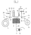
- FIG. 1 seen from left to right, one can see the supply roll 1 for the metal foil 2, which, via deflection rolls 3 and 4 and a tension measuring and setting device 5, here called tension regulator for short, to a metering device 6 for light, UV-curable adhesive in particular, where the edge is coated with the adhesive in a narrow overlap area, preferably 3 mm wide, and reaches the two pressure rollers 7 and 8.
- a tension measuring and setting device 5 here called tension regulator for short
- the plastic film 13 is pulled off the supply spool 14 and passed over the deflection rollers 15 and 16 and adjusted to the required voltage by the voltage regulator 17. Shortly before the pressure rollers 7 and 8, at least the edge of the plastic film to be glued is passed through a corona discharge station 18 in order to achieve better wettability for the adhesive by increasing the surface energy. This treatment will achieved that on the one hand the connection metal / plastic is improved and on the other hand a relatively small overlap is necessary to produce the necessary tensile strength.
- both foils are combined and then arrive at the polymerization device 9, in which the adhesive point is irradiated with UV light.
- the assembled composite film 10 reaches a punching tool (not shown) via a roller 11 and a pressing device 12 in order to produce ready-to-use matrices.
- the two rollers 1 and 14 are driven.
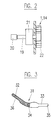
- the shaft 19 is driven by a motor 20, a step-up gear 21 being connected to the shaft, which has, for example, a step-up ratio of 1:40 and acts on the coil 22.
- the voltage regulator 5 contains a load cell 23, which is arranged on a lever 25 provided with a deflection roller 24, a pneumatically driven cylinder 26 acting on the lever in order to generate a tension of, for example, 50 N on the deflection roller 24.
- the load cell 27 of the voltage regulator 17 is arranged on a lever 28, which is also acted upon by a force which, for example, consists of a weight 29 in order to exert a tensioning force on the deflection roller 30.
- This tension must of course be less to the plastic film to tension and can be, for example, 2 N. It is important that the stretching of the two films is approximately the same amount in order to prevent the joint film from winding up like an angel hair after the polymerization after the polymerization.
- the station 18 for generating a corona discharge is known per se and need not be explained in more detail here.
- the two supply rolls 1 and 14, or the foils are mutually displaced in such a way that only a relatively narrow overlap of 2 to 4 mm, preferably 3 mm, is produced.
- the roller 11 is also driven by a motor, while the pressing device 12 has suitable counter rollers.
- the subsequent punching device is not shown here and can be assumed to be known per se.
- the dies according to FIG. 3 are punched out in the punching device, the die 31 consisting of a metal part 32 and a transparent plastic part 33 and the overlap 34 being shown symbolically.
- the two ends 35 and 36 of the die are narrower than the middle part in order to be able to insert these ends comfortably into the die clamping device.
- the two different materials do not necessarily have to be connected to one another as shown in FIG. 3, it could also be conceivable for different applications to join the two materials lengthwise or in another arrangement.
- the steel foil has a thickness of 0.038 mm. However, it can also have a thickness of 0.020 to 0.060 mm, in particular 0.030 to 0.040 mm.
- the UV-curable adhesive manufactured under the trade name Dimax! 128-M by Dimax Corporation is particularly advantageous and has a tensile strength which was considered to be completely sufficient in the subsequent clinical trials.
- the invention is not limited to this adhesive.
- Other light and UV curable adhesives with similar bond properties and compatibility, such as known under the trade name Delo-Photobond or a one-component UV-curable acrylate adhesive can also be used.
Landscapes
- Engineering & Computer Science (AREA)
- Mechanical Engineering (AREA)
- Health & Medical Sciences (AREA)
- Oral & Maxillofacial Surgery (AREA)
- Dentistry (AREA)
- Epidemiology (AREA)
- Life Sciences & Earth Sciences (AREA)
- Animal Behavior & Ethology (AREA)
- General Health & Medical Sciences (AREA)
- Public Health (AREA)
- Veterinary Medicine (AREA)
- Physics & Mathematics (AREA)
- Electromagnetism (AREA)
- Toxicology (AREA)
- Lining Or Joining Of Plastics Or The Like (AREA)
- Adhesives Or Adhesive Processes (AREA)
Abstract
Description
Die vorliegende Erfindung bezieht sich auf ein Verfahren zur Verbindung einer Metallfolie mit einer Kunststoff-Folie und auf die Herstellung einer Matrize für die DentalMedizin, die aus einem Metall- und Kunststoffteil besteht.The present invention relates to a method for connecting a metal foil to a plastic foil and to the production of a matrix for dental medicine, which consists of a metal and plastic part.
Eine solche kombinierte Matrize ist in der US-A-5,330,353 beschrieben und klinische Tests haben bewiesen, dass das metallische Teil der Matrize deren Einführung zwischen zwei Zähnen begünstigt, während der Kunststoffteil unabdingbar ist für die Belichtung von Zahnfüllungen aus polymerisierendem Kunststoff. In dieser US-Patentschrift werden relativ wenig Angaben zur Herstellung einer solchen kombinierten Matrize gegeben, es wird lediglich von der Verbindung der Metallfolie mit der Kunststoff-Folie durch Mikroätzen und Heissverkleben offenbart.Such a combined matrix is described in US-A-5,330,353 and clinical tests have proven that the metallic part of the matrix promotes its insertion between two teeth, while the plastic part is essential for the exposure of dental fillings made of polymerizing plastic. In this US patent, relatively little information is given on the production of such a combined die, it is only disclosed of the connection of the metal foil to the plastic foil by microetching and hot gluing.
Aus der FR-A-2 553 029 ist ein Verfahren zur Herstellung eines thermoverformbaren Verbudmaterials aus Polyethylen und Metallfolie bekannt, das vor allem zur Herstellung von Schuhsohlen dient.From FR-A-2 553 029 a method for producing a thermoformable composite material made of polyethylene and metal foil is known, which is used primarily for the production of shoe soles.
Aus der Database WPI, Section Ch, Week 8035, ist ein Verfahren zur Beschichtung einer Stahlfolie mit einer Kunststoff-Schicht bekannt, wobei ein UV-härtbarer Kleber verwendet wird.A method for coating a steel foil with a plastic layer is known from the database WPI, Section Ch, Week 8035, a UV-curable adhesive being used.
Angesichts der erwünschten geringen Dicken der Folien einerseits und ihrer benötigten, relativ hohen Zerreissfestigkeit andererseits, die durch die zu verwendenden Matrizenspanner bedingt wird, ist es Aufgabe der vorliegenden Erfindung, ein Verfahren zur Herstellung einer Verbindung zwischen einer Metallfolie und einer Kunststoff-Folie und zur Herstellung einer Verbund-Matrize für die Dentalmedizin anzugeben, das das Verbinden von sehr dünnen Folien gestattet und eine hohe Zerreissfestigkeit aufweist. Solche Verfahren werden in den unabhängigen Ansprüchen 1 und 2 definiert. Die abhängigen Ansprüche beschreiben Weiterentwicklungen und Verbesserungen der in den unabhängigen Ansprüchen 1 und 2 definierten Verfahren.In view of the desired low thicknesses of the foils on the one hand and their required, relatively high tensile strength on the other hand, which is caused by the die clamps to be used, the object of the present invention is a method for producing a connection between a metal foil and a plastic foil and for producing it a composite matrix for dental medicine, which allows the connection of very thin foils and has a high tensile strength. Such methods are defined in
Die Erfindung wird im folgenden anhand einer Zeichnung näher erläutert.
Figur 1- zeigt schematisch eine Vorrichtung zur Durchführung der erfindungsgemässen Verfahren,
Figur 2- zeigt eine Ausschnittsvergrösserung aus der Vorrichtung gemäss
Figur 1 und Figur 3- zeigt eine nach dem Verfahren hergestellte Matrize.
- Figure 1
- schematically shows a device for carrying out the method according to the invention,
- Figure 2
- shows an enlarged detail of the device according to Figure 1 and
- Figure 3
- shows a die produced by the method.
In Figur 1 erkennt man, von links nach rechts gesehen, die Vorratsrolle 1 für die Metallfolie 2, die über Umlenkrollen 3 und 4 und einer Spannungsmess- und -Einstellvorrichtung 5, hier kurz Spannungsregler genannt, an eine Dosier-Einrichtung 6 für Licht-, insbesondere UV-härtbaren Klebstoff gelangt, wo der Rand in einem schmalen Ueberlappungsbereich von vorzugsweise 3 mm Breite mit dem Klebstoff bestrichen wird und zu den beiden Anpressrollen 7 und 8 gelangt.In FIG. 1, seen from left to right, one can see the
Die Kunststoff-Folie 13 wird von der Vorratsspule 14 abgezogen und über die Umlenkrollen 15 und 16 geleitet sowie durch den Spannungsregler 17 auf die nötige Spannung eingestellt. Kurz vor den Anpressrollen 7 und 8 wird mindestens der zu verklebende Rand der Kunststoff-Folie durch eine Koronaentladungs-Station 18 geleitet, um durch Erhöhung der Oberflächen-Energie eine bessere Benetzbarkeit für den Klebstoff zu erzielen. Durch diese Behandlung wird erreicht, dass einerseits die Verbindung Metall/Kunststoff verbessert wird und andererseits eine relativ kleine Ueberlappung notwendig ist, um die notwendige Zerreissfestigkeit herzustellen.The
Bei den Anpressrollen 7 und 8 werden beide Folien vereinigt und gelangen dann zur Polymerisationseinrichtung 9, in der die Klebstelle mit UV-Licht bestrahlt wird. Bei der Herstellung von Verbundmatrizen für die Dentaltechnik gelangt die zusammengefügte Verbundfolie 10 über eine Rolle 11 und über eine Anpressvorrichtung 12 zu einem nicht dargestellten Stanzwerkzeug, um gebrauchsfertige Matrizen herzustellen.In the case of the pressure rollers 7 and 8, both foils are combined and then arrive at the
Die beiden Rollen 1 und 14 werden angetrieben. Im Ausführungsbeispiel gemäss Figur 2 wird die Welle 19 von einem Motor 20 angetrieben, wobei mit der Welle ein Uebersetzungsgetriebe 21 verbunden ist, das beispielsweise ein Uebersetzungsverhältnis von 1:40 aufweist und auf die Spule 22 wirkt.The two
Die beiden Spannungsregler 5 und 17 haben im Prinzip die gleiche Aufgabe, doch ist die Lösung jeweils verschieden, da verschiedene Kräfte auf die Metallfolie oder auf die Kunststoff-Folie wirken sollen. Der Spannungsregler 5 enthält eine Messdose 23, die an einem mit einer Umlenkrolle 24 versehenen Hebel 25 angeordnet ist, wobei ein pneumatisch angetriebener Zylinder 26 auf den Hebel wirkt, um eine Spannung von beispielsweise 50 N an der Umlenkrolle 24 zu erzeugen.In principle, the two
Die Messdose 27 des Spanungsreglers 17 ist an einem Hebel 28 angeordnet, auf den ebenfalls eine Kraft wirkt, die beispielsweise aus einem Gewicht 29 besteht, um auf die Umlenkrolle 30 eine Spannkraft auszuüben. Diese Spannkraft muss selbstverständlich geringer sein, um die Kunststoff-Folie zu spannen und kann beispielsweise 2 N betragen. Wichtig ist, dass die Dehnung der beiden Folien etwa den gleichen Betrag ausmachen, um zu verhindern, dass nach dem Zusammenkleben die gemeinsame Folie nach der Polymerisation sich wie ein Engelhaar aufwickelt.The
Die Station 18 zur Erzeugung einer Koronaentladung ist an sich bekannt und braucht hier nicht näher erläutert zu werden.The
Aus der Beschreibung ist ersichtlich, dass die beiden Vorratsrollen 1 und 14, bzw. die Folien derart gegeneinander verschoben sind, dass nur eine relativ schmale Ueberlappung von 2 bis 4 mm, vorzugsweise 3 mm entsteht. Selbstverständlich kann je nach Klebstoff und/oder Material eine verschieden breite Ueberlappung optimal sein. Die Rolle 11 ist ebenfalls von einem Motor angetrieben, während die Anpressvorrichtung 12 geeignete Gegenrollen aufweist. Die anschliessende Stanzvorrichtung ist hier nicht dargestellt und kann als an sich bekannt vorausgesetzt werden.From the description it can be seen that the two
In der Stanzvorrichtung werden die Matrizen gemäss Figur 3 herausgestanzt, wobei die Matrize 31 aus einem Metallteil 32 und einem durchsichtigen Kunststoffteil 33 besteht und die Ueberlappung 34 symbolisch dargestellt ist. Die beiden Enden 35 und 36 der Matrize sind schmäler als das Mittelteil, um diese Enden bequem in das Matrizenspanngerät stecken zu können. Die beiden verschiedenen Materialien müssen jedoch nicht notwendigerweise wie in Figur 3 dargestellt miteinander verbunden sein, es könnte für verschiedene Anwendungen auch denkbar sein, die beiden Materialien längsweise oder in einer anderen Anordnung zusammenzufügen.The dies according to FIG. 3 are punched out in the punching device, the
In vorliegendem Beipsiel weist die Stahlfolie eine Dicke von 0,038 mm auf. Sie kann aber auch eine Dicke von 0,020 bis 0,060 mm, insbesondere von 0,030 bis 0,040 mm aufweisen. Als Kunststoff-Folie wurde eine Polyesterfolie, insbesondere eine unter dem Handelsnamen Mylar bekannte Polyethylenterephtalat-Folie verwendet, mit der für Matrizen üblichen Dicke von 0,04 bis 0,08 mm.In the present example, the steel foil has a thickness of 0.038 mm. However, it can also have a thickness of 0.020 to 0.060 mm, in particular 0.030 to 0.040 mm. A polyester film, in particular a polyethylene terephthalate film known under the trade name Mylar, was used as the plastic film, with the thickness of 0.04 to 0.08 mm customary for matrices.
Bei der Verwendung von oben beschriebenen Stahlfolien und Polyesterfolien und bei der Vorbehandlung der Kunststoff-Folie durch eine Koronaentladung stellte es sich heraus, dass der unter dem Handelsnamen Dimax!128-M der Dimax Corporation hergestellte, UV-härtbare Klebstoff besonders vorteilhaft ist und eine Zugfestigkeit erbrachte, die bei den anschliessenden klinischen Versuchen als völlig ausreichend erachtet wurde. Selbstverständlich ist die Erfindung nicht auf diesen Klebstoff beschränkt. Andere Licht- und UV-härtbare Klebstoffe mit ähnlichen Verbundeigenschaften und Verträglichkeit, wie z.B. unter dem Handelsnamen Delo-Photobond bekannt oder ein Einkomponenten-UV-härtbarer Acrylat-Klebstoff können auch verwendet werden.When using the steel foils and polyester foils described above and when pretreating the plastic foil by means of a corona discharge, it turned out that the UV-curable adhesive manufactured under the trade name Dimax! 128-M by Dimax Corporation is particularly advantageous and has a tensile strength which was considered to be completely sufficient in the subsequent clinical trials. Of course, the invention is not limited to this adhesive. Other light and UV curable adhesives with similar bond properties and compatibility, such as known under the trade name Delo-Photobond or a one-component UV-curable acrylate adhesive can also be used.
Claims (8)
Applications Claiming Priority (3)
| Application Number | Priority Date | Filing Date | Title |
|---|---|---|---|
| CH107696 | 1996-04-29 | ||
| CH107696 | 1996-04-29 | ||
| CH1076/96 | 1996-04-29 |
Publications (2)
| Publication Number | Publication Date |
|---|---|
| EP0805193A1 true EP0805193A1 (en) | 1997-11-05 |
| EP0805193B1 EP0805193B1 (en) | 2001-06-13 |
Family
ID=4201904
Family Applications (1)
| Application Number | Title | Priority Date | Filing Date |
|---|---|---|---|
| EP97810202A Expired - Lifetime EP0805193B1 (en) | 1996-04-29 | 1997-04-08 | Method for bonding a metal sheet with a plastic film |
Country Status (4)
| Country | Link |
|---|---|
| US (1) | US5951801A (en) |
| EP (1) | EP0805193B1 (en) |
| DE (1) | DE59703753D1 (en) |
| PL (1) | PL319716A1 (en) |
Families Citing this family (8)
| Publication number | Priority date | Publication date | Assignee | Title |
|---|---|---|---|---|
| DE19824798A1 (en) * | 1998-06-03 | 1999-12-09 | Indag Gmbh & Co Betriebs Kg | Device and method for feeding foils |
| US6482005B1 (en) * | 1999-12-16 | 2002-11-19 | John Summer | Method and apparatus for shaping dental filling material |
| US20030014947A1 (en) * | 2001-07-19 | 2003-01-23 | Sarojini Deevi | Laminated metal foil packaging material and method of making |
| US7094307B2 (en) * | 2003-01-06 | 2006-08-22 | Joan Morris | Methods for coating surfaces with metal and products made thereby |
| US20050287491A1 (en) * | 2004-03-18 | 2005-12-29 | Slone Charles E | Bi-laminate martix and method of use |
| US7214058B2 (en) * | 2004-04-09 | 2007-05-08 | Dental Innovations Llc | Dental matrix positioned by slidably engaged matrix retainer |
| WO2019084523A2 (en) | 2017-10-27 | 2019-05-02 | Aero Advanced Paint Technology, Inc. | Method for applying a polymeric film to a substrate and resulting articles |
| SI3684851T1 (en) * | 2017-10-27 | 2024-08-30 | Ppg Advanced Surface Technologies, Llc | Method for applying a polymeric film to a substrate and resulting articles |
Citations (8)
| Publication number | Priority date | Publication date | Assignee | Title |
|---|---|---|---|---|
| JPS5595565A (en) * | 1979-01-13 | 1980-07-19 | Matsushita Electric Works Ltd | Steel plate coated with resin and its preparation |
| EP0124847A2 (en) * | 1983-05-06 | 1984-11-14 | Shin-Etsu Chemical Co., Ltd. | A flexible base plate for printed circuit board and a method for the preparation thereof |
| FR2553029A1 (en) * | 1983-10-07 | 1985-04-12 | Allibert Sa | Article, which can be thermoformed under pressure, having an incorporated electrical-heating body, and method for manufacturing this article |
| US4523909A (en) * | 1984-03-06 | 1985-06-18 | Lazarus Harry J | Plastic dental matrix and method of manufacturing same |
| EP0180901A2 (en) * | 1984-11-02 | 1986-05-14 | Adolph Coors Company | Laminating device with longitudinal and lateral stretch control |
| FR2575450A1 (en) * | 1984-12-27 | 1986-07-04 | Colgate Palmolive Co | DEVICE FOR ADJUSTING THE ELONGATION FOR BAND MATERIALS TO BE ASSEMBLED OR JOINED BY LAMINATION |
| US5330353A (en) * | 1993-03-17 | 1994-07-19 | Wavrin Dennis L | Matrix band |
| US5393818A (en) * | 1993-04-06 | 1995-02-28 | Shell Oil Company | Solvent-free laminating adhesive composition from epoxidized block polymer |
Family Cites Families (5)
| Publication number | Priority date | Publication date | Assignee | Title |
|---|---|---|---|---|
| US1410879A (en) * | 1921-01-10 | 1922-03-28 | American Box Board Co | Method of connecting and corrugating paper |
| GB1226199A (en) * | 1967-12-30 | 1971-03-24 | ||
| US3776798A (en) * | 1972-01-31 | 1973-12-04 | Arvey Corp | Method of making pouches |
| US4105118A (en) * | 1976-06-10 | 1978-08-08 | Eastman Kodak Company | Laminates useful as packaging materials and container having alkaline fluid means |
| US4496417A (en) * | 1982-11-12 | 1985-01-29 | Adolph Coors Company | Control stretch laminating device |
-
1997
- 1997-04-08 EP EP97810202A patent/EP0805193B1/en not_active Expired - Lifetime
- 1997-04-08 DE DE59703753T patent/DE59703753D1/en not_active Expired - Fee Related
- 1997-04-28 PL PL97319716A patent/PL319716A1/en unknown
- 1997-04-29 US US08/848,234 patent/US5951801A/en not_active Expired - Fee Related
Patent Citations (8)
| Publication number | Priority date | Publication date | Assignee | Title |
|---|---|---|---|---|
| JPS5595565A (en) * | 1979-01-13 | 1980-07-19 | Matsushita Electric Works Ltd | Steel plate coated with resin and its preparation |
| EP0124847A2 (en) * | 1983-05-06 | 1984-11-14 | Shin-Etsu Chemical Co., Ltd. | A flexible base plate for printed circuit board and a method for the preparation thereof |
| FR2553029A1 (en) * | 1983-10-07 | 1985-04-12 | Allibert Sa | Article, which can be thermoformed under pressure, having an incorporated electrical-heating body, and method for manufacturing this article |
| US4523909A (en) * | 1984-03-06 | 1985-06-18 | Lazarus Harry J | Plastic dental matrix and method of manufacturing same |
| EP0180901A2 (en) * | 1984-11-02 | 1986-05-14 | Adolph Coors Company | Laminating device with longitudinal and lateral stretch control |
| FR2575450A1 (en) * | 1984-12-27 | 1986-07-04 | Colgate Palmolive Co | DEVICE FOR ADJUSTING THE ELONGATION FOR BAND MATERIALS TO BE ASSEMBLED OR JOINED BY LAMINATION |
| US5330353A (en) * | 1993-03-17 | 1994-07-19 | Wavrin Dennis L | Matrix band |
| US5393818A (en) * | 1993-04-06 | 1995-02-28 | Shell Oil Company | Solvent-free laminating adhesive composition from epoxidized block polymer |
Non-Patent Citations (1)
| Title |
|---|
| DATABASE WPI Section Ch Week 8035, Derwent World Patents Index; Class A32, AN 80-61592C, XP002021462 * |
Also Published As
| Publication number | Publication date |
|---|---|
| EP0805193B1 (en) | 2001-06-13 |
| US5951801A (en) | 1999-09-14 |
| PL319716A1 (en) | 1997-11-10 |
| DE59703753D1 (en) | 2001-07-19 |
Similar Documents
| Publication | Publication Date | Title |
|---|---|---|
| EP0586642B1 (en) | Process, device and installation for producing laminates | |
| EP0805193B1 (en) | Method for bonding a metal sheet with a plastic film | |
| DE2166968B2 (en) | Method for making a composite web | |
| WO2007042098A1 (en) | Method and device for bundling steel coils and binding tape for this | |
| DE19521022C2 (en) | Process for producing a layered composite | |
| DE3781150T4 (en) | BROCHURE OR SIMILAR, METHOD AND DEVICE FOR PRODUCING THE SAME. | |
| DE102005006978B3 (en) | Method for joining semiconductor components with a flexible support band comprises moving an endless band parallel to the running direction of the support band between heating elements and the components | |
| DE102010004092A1 (en) | Workpiece edge creating device, has press member laid out in edge tape with pulsating pressure, where edge tape is advanced into region of pressure zone by relative movement of workpiece and edge tape to narrow side of workpiece | |
| DE69810414T2 (en) | Method and device for producing thermoplastic composite films | |
| EP2020195A2 (en) | Method for manufacturing a foldable panel | |
| DE60320638T2 (en) | PROCESS FOR HOT GLUE | |
| DE3403364A1 (en) | Process and device for producing strip-like adhesive label material, and a self-adhesive label | |
| DE2106683C3 (en) | Device for tensioning bands cut into strips | |
| DE3433293A1 (en) | Self-adhesive plastics film and process for the production thereof | |
| DE4033834A1 (en) | METHOD FOR PRODUCING AN INTERRUPTED STICKER SHEET | |
| EP0498040B1 (en) | Method of manufacturing documents with security marks | |
| EP1590414A1 (en) | Adhesive tape and use thereof for sticking printing blankets together | |
| DE102021102869B4 (en) | Methods of aligning optical fibers and apparatus for use in the methods | |
| DE4442920C2 (en) | Process for producing a film composite | |
| EP1136253A2 (en) | Method for producing a double layer metal sheet and a piece, in particular a stove-enameled piece, formed therefrom , and a deep-drawable double layer metal sheet | |
| DE102008004544B3 (en) | Hump composite plate and method for its production | |
| EP2117841A1 (en) | Laminating process and apparatus for applying an adhesive-composition film to a web-like substrate | |
| WO1995027799A1 (en) | Skiving machine for flat supple material, particularly leather, as well as use of the machine and process for relief skiving and appropriate template | |
| EP0798101B1 (en) | Method and apparatus for thickening at least one edge of plastic sheeting and produced sheet. | |
| DE2941277C2 (en) | Method for producing a laminate from flexible decorative material and a carrier material web |
Legal Events
| Date | Code | Title | Description |
|---|---|---|---|
| PUAI | Public reference made under article 153(3) epc to a published international application that has entered the european phase |
Free format text: ORIGINAL CODE: 0009012 |
|
| AK | Designated contracting states |
Kind code of ref document: A1 Designated state(s): CH DE FR IT LI |
|
| 16A | New documents despatched to applicant after publication of the search report | ||
| 17P | Request for examination filed |
Effective date: 19980417 |
|
| 17Q | First examination report despatched |
Effective date: 19990526 |
|
| GRAG | Despatch of communication of intention to grant |
Free format text: ORIGINAL CODE: EPIDOS AGRA |
|
| GRAG | Despatch of communication of intention to grant |
Free format text: ORIGINAL CODE: EPIDOS AGRA |
|
| GRAH | Despatch of communication of intention to grant a patent |
Free format text: ORIGINAL CODE: EPIDOS IGRA |
|
| GRAH | Despatch of communication of intention to grant a patent |
Free format text: ORIGINAL CODE: EPIDOS IGRA |
|
| GRAA | (expected) grant |
Free format text: ORIGINAL CODE: 0009210 |
|
| AK | Designated contracting states |
Kind code of ref document: B1 Designated state(s): CH DE FR IT LI |
|
| REG | Reference to a national code |
Ref country code: CH Ref legal event code: NV Representative=s name: AMMANN PATENTANWAELTE AG BERN * AMMANN PATENTANWAE |
|
| ITF | It: translation for a ep patent filed | ||
| REF | Corresponds to: |
Ref document number: 59703753 Country of ref document: DE Date of ref document: 20010719 |
|
| ET | Fr: translation filed | ||
| PGFP | Annual fee paid to national office [announced via postgrant information from national office to epo] |
Ref country code: FR Payment date: 20020328 Year of fee payment: 6 |
|
| PLBE | No opposition filed within time limit |
Free format text: ORIGINAL CODE: 0009261 |
|
| STAA | Information on the status of an ep patent application or granted ep patent |
Free format text: STATUS: NO OPPOSITION FILED WITHIN TIME LIMIT |
|
| PGFP | Annual fee paid to national office [announced via postgrant information from national office to epo] |
Ref country code: CH Payment date: 20020426 Year of fee payment: 6 |
|
| PGFP | Annual fee paid to national office [announced via postgrant information from national office to epo] |
Ref country code: DE Payment date: 20020527 Year of fee payment: 6 |
|
| 26N | No opposition filed | ||
| REG | Reference to a national code |
Ref country code: CH Ref legal event code: PVP |
|
| PG25 | Lapsed in a contracting state [announced via postgrant information from national office to epo] |
Ref country code: LI Free format text: LAPSE BECAUSE OF NON-PAYMENT OF DUE FEES Effective date: 20030430 Ref country code: CH Free format text: LAPSE BECAUSE OF NON-PAYMENT OF DUE FEES Effective date: 20030430 |
|
| PG25 | Lapsed in a contracting state [announced via postgrant information from national office to epo] |
Ref country code: DE Free format text: LAPSE BECAUSE OF NON-PAYMENT OF DUE FEES Effective date: 20031101 |
|
| REG | Reference to a national code |
Ref country code: CH Ref legal event code: PL |
|
| PG25 | Lapsed in a contracting state [announced via postgrant information from national office to epo] |
Ref country code: FR Free format text: LAPSE BECAUSE OF NON-PAYMENT OF DUE FEES Effective date: 20031231 |
|
| REG | Reference to a national code |
Ref country code: FR Ref legal event code: ST |
|
| PG25 | Lapsed in a contracting state [announced via postgrant information from national office to epo] |
Ref country code: IT Free format text: LAPSE BECAUSE OF NON-PAYMENT OF DUE FEES;WARNING: LAPSES OF ITALIAN PATENTS WITH EFFECTIVE DATE BEFORE 2007 MAY HAVE OCCURRED AT ANY TIME BEFORE 2007. THE CORRECT EFFECTIVE DATE MAY BE DIFFERENT FROM THE ONE RECORDED. Effective date: 20050408 |