EP0805072A2 - Gasgenerator - Google Patents
Gasgenerator Download PDFInfo
- Publication number
- EP0805072A2 EP0805072A2 EP97107182A EP97107182A EP0805072A2 EP 0805072 A2 EP0805072 A2 EP 0805072A2 EP 97107182 A EP97107182 A EP 97107182A EP 97107182 A EP97107182 A EP 97107182A EP 0805072 A2 EP0805072 A2 EP 0805072A2
- Authority
- EP
- European Patent Office
- Prior art keywords
- tubular insert
- gas generator
- housing
- combustion chamber
- gas
- Prior art date
- Legal status (The legal status is an assumption and is not a legal conclusion. Google has not performed a legal analysis and makes no representation as to the accuracy of the status listed.)
- Granted
Links
- 238000002485 combustion reaction Methods 0.000 claims abstract description 33
- 239000003380 propellant Substances 0.000 claims description 19
- 238000011045 prefiltration Methods 0.000 claims description 8
- 239000004449 solid propellant Substances 0.000 claims description 8
- 230000002093 peripheral effect Effects 0.000 claims description 6
- 239000000463 material Substances 0.000 claims description 2
- 239000007789 gas Substances 0.000 description 57
- 239000000446 fuel Substances 0.000 description 5
- 238000004519 manufacturing process Methods 0.000 description 4
- VOPWNXZWBYDODV-UHFFFAOYSA-N Chlorodifluoromethane Chemical compound FC(F)Cl VOPWNXZWBYDODV-UHFFFAOYSA-N 0.000 description 3
- 238000001816 cooling Methods 0.000 description 3
- 238000009413 insulation Methods 0.000 description 3
- 239000002245 particle Substances 0.000 description 3
- 229910000838 Al alloy Inorganic materials 0.000 description 1
- 230000015572 biosynthetic process Effects 0.000 description 1
- 238000005253 cladding Methods 0.000 description 1
- 239000000567 combustion gas Substances 0.000 description 1
- 238000010276 construction Methods 0.000 description 1
- 238000005516 engineering process Methods 0.000 description 1
- 239000000945 filler Substances 0.000 description 1
- 239000002737 fuel gas Substances 0.000 description 1
- 238000000034 method Methods 0.000 description 1
- 230000000284 resting effect Effects 0.000 description 1
- 238000000926 separation method Methods 0.000 description 1
- 239000007787 solid Substances 0.000 description 1
Images

Classifications
-
- B—PERFORMING OPERATIONS; TRANSPORTING
- B60—VEHICLES IN GENERAL
- B60R—VEHICLES, VEHICLE FITTINGS, OR VEHICLE PARTS, NOT OTHERWISE PROVIDED FOR
- B60R21/00—Arrangements or fittings on vehicles for protecting or preventing injuries to occupants or pedestrians in case of accidents or other traffic risks
- B60R21/02—Occupant safety arrangements or fittings, e.g. crash pads
- B60R21/16—Inflatable occupant restraints or confinements designed to inflate upon impact or impending impact, e.g. air bags
- B60R21/26—Inflatable occupant restraints or confinements designed to inflate upon impact or impending impact, e.g. air bags characterised by the inflation fluid source or means to control inflation fluid flow
- B60R21/264—Inflatable occupant restraints or confinements designed to inflate upon impact or impending impact, e.g. air bags characterised by the inflation fluid source or means to control inflation fluid flow using instantaneous generation of gas, e.g. pyrotechnic
- B60R21/2644—Inflatable occupant restraints or confinements designed to inflate upon impact or impending impact, e.g. air bags characterised by the inflation fluid source or means to control inflation fluid flow using instantaneous generation of gas, e.g. pyrotechnic using only solid reacting substances, e.g. pellets, powder
Definitions
- the invention relates to a gas generator that generates propellant gas for inflating a gas bag in an airbag system, with a housing with outflow openings for the exit of the propellant gas from the housing into the gas bag, with a filter device in front of the outflow openings and with an ignition device for igniting one in the combustion chamber located solid propellant, wherein the propellant gas emerging from the combustion chamber is led out of the housing via flow spaces, with a combustion chamber which is formed in the interior of the housing by an upper housing part, a lower housing part and by an interior of a tubular insert which is between the upper housing part and lower housing part is held stationary, wherein the tubular insert has outlet openings in an annular flow space between the tubular insert and the housing and means are provided on the outer peripheral surface of the tubular insert with which the Fil Tervvoretti is held between the tubular insert and the housing.
- Such a gas generator is known for example from US-A-5 189 255.
- Airbag systems are installed in vehicles in order to reduce the kinetic energy of the vehicle occupants in the event of a crash and to protect the vehicle occupants from impact with hard vehicle interior parts, such as the steering wheel or side panels of the vehicle doors. If a sensor system of the airbag system detects an impact accident of the vehicle, a fuel, usually in tablet form, is ignited within the gas generator, which burns under high pressure in the combustion chamber housing and thus generates a propellant gas. This propellant is used to fill an airbag, which the vehicle occupants encounter in the event of a collision of the vehicle.
- Gas generators in which the axial height is smaller than the radial diameter of the gas generator are referred to as so-called round gas generators.
- a gas generator known from DE-A-41 35 299 has a two-part housing, the two parts of which are screwed together.
- a combustion chamber is provided in the axially symmetrical housing and contains a solid propellant in tablet form.
- an ignition unit near the combustion chamber that ignites the fuel is activated via an electrical current pulse.
- the fuel burns off under high pressure, and the propellant gas produced in this way escapes via radial outlet openings in a combustion chamber housing, flows through predetermined flow spaces through flow plates, is cleaned in a filter unit and flows out of the gas generator into the gas bag via outlet openings of a cladding plate.
- the flow plates on the one hand form a cyclone, which brings about a positive guidance for the propellant gas in the desired manner, so that not only a multiple flow deflection, but also a separation of small particles takes place.
- the flow plates also serve to keep themselves spaced apart for a sufficiently relaxed gas flow into and through the filter device.
- these flow plates must already be inserted into corresponding receptacles in both housing parts and must be fixed in position during the screwing of both housing parts and protected against tilting.
- the assembly of the gas generator is therefore laborious by hand, or correspondingly complicated devices must be provided for assembling the gas generator. Since the flow spaces in the known gas generator are formed by at least four flow plates, the number of individual parts required for the gas generator is also corresponding high. The formation of the special shapes of the flow plates also requires complex production.
- a gas generator which has an essentially cup-shaped, two-part housing.
- an ignition device is provided for igniting a pyrotechnic charge, the combustion gases of which emerge from the combustion chamber through outlet openings and are passed via flow spaces to a filter device before they flow into the gas bag from the gas generator.
- This known gas generator comprises a large number of individual parts and in particular the flow spaces and the filter device are formed outside the actual combustion chamber housing, which requires additional fastening parts.
- a round gas generator with a tubular insert is known from US-A-5 189 255, said gas generator having insert outlet openings and means on its outer peripheral surface with which the filter device is held between the tubular insert and the housing. These means are formed by a radially outwardly projecting ring flange with jagged extensions.
- the invention provides a housing for a gas generator that can be manufactured easily and inexpensively. This is achieved in an insert of the type mentioned above in that the tubular insert has radially angled tabs through which the outlet openings are formed in the tubular insert on the one hand and on the other hand as means on the outer peripheral surface of the tubular insert for holding the filter device serve.
- the gas generator according to the invention thus has the essential advantage that the number of individual components due to the simplified construction of the gas generator with inexpensive manufacture is significantly reduced.
- the tubular insert forms both the combustion chamber and the flow guide for the propellant gases emerging from the combustion chamber as well as the holder for the filter device.
- the tubular insert does not need to be connected to the housing parts themselves, but can be easily fixed in the housing by means of corresponding positive connections when connecting the upper and lower parts of the housing. This simple connection technology can further simplify the assembly of the gas generator and reduce the weight of the gas generator.
- the radially outwardly angled tabs of the tubular insert form the outlet openings in the tubular insert.
- the sections between adjacent incisions can be angled slightly to, for example, radially outwardly extending tabs.
- the axial depth of the incisions corresponds approximately to the radial extent of the flow space between the gas generator housing and the tubular insert.
- the tabs serve on the one hand as flow baffles for the propellant gases flowing into the flow space, so that the flow path covered by the propellant gases up to the outlet from the housing is lengthened and the gases are better cooled and further cleaned by deposits of hot particles.
- the filter device can be arranged particularly easily, in particular directly in front of the outflow openings of the gas generator, by resting on the angled tabs in the housing.
- Another embodiment is characterized in that the filter device in front of the outlet openings of the housing is also designed as heat insulation. This heat insulation prevents the heat from the generator housing from flowing over the outflow openings into the gas bag.
- a pre-filter device is provided in the combustion chamber immediately in front of the outlet openings of the tubular insert. This pre-filter device serves on the one hand to fix the solid propellant in the combustion chamber, but on the other hand also as a cooling and filter medium.
- this pre-filter device is ring-shaped, so that it fits positively on the tubular insert and thus no special holder for the pre-filter device has to be provided in the combustion chamber.
- a further embodiment consists in that a filling material for fixing the solid propellant is provided in the combustion chamber.
- the solid propellant which is usually in tablet form, can be packed on all sides, in particular also tightly, thereby preventing the tablets from rattling when the gas generator is shaken when in use in a moving vehicle.
- a pre-ignition device is also preferably arranged in the combustion chamber.
- the auto-ignition temperature of the fuels used today is around 400 ° C.
- the gas generator housing is now mainly made from an aluminum alloy, the low strength of which is known at high temperatures. Therefore, in order to fulfill a legally prescribed fire test for this type of gas generator, a pre-ignition device must be integrated into the gas generator, which causes the propellant to ignite at a temperature below 400 ° C but above typical operating temperatures of up to 100 ° C.
- the upper housing part and the lower housing part are connected to one another via a radial rivet connection.
- This connection is particularly easy to form and simple to establish automatically.
- annular mounting flange is attached to the outer circumference of the housing, so that this can be screwed onto the airbag module, for example, via a screw connection.
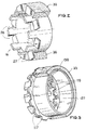
- FIG. 3 which is first explained, shows a known use of a gas generator according to the prior art.
- the tubular insert has outlet openings on its outer circumferential surface and a radially outwardly projecting ring flange with prong-like extensions 117.
- the ring flange delimits a filter 33 with the outer circumferential surface 130.
- the geometry of the tubular insert is very complicated, so that it is complex to manufacture.
- FIG. 1 shows a gas generator 10 according to the invention, the housing 11 of which essentially consists of a pot-like housing upper part 12 and a bottom-shaped housing lower part 13.
- This lower housing part 13 lies with its inside against a contact surface 14 of the upper housing part 12 and is fastened to the upper housing part 12 via a radial rivet connection 15 by the free axial ends 16 of the upper housing part 12 being bent inwards onto the outer surface 17 of the lower housing part 13.
- a tubular insert 18 is fixed in position in contact with axial projections 19, 20 of the upper housing part 12 and the lower housing part 13.
- the space enclosed by the tubular insert 18, the upper housing part 12 and the lower housing part 13 forms a combustion chamber 21 in which there is a solid propellant 22 in tablet form.
- an ignition device 23 is also fastened to the lower housing part 13 and a pre-ignition unit 24 to the upper housing part 12.
- a filler 25 is also introduced into the combustion chamber 21, which fills the free volume in the combustion chamber 21.
- An annular first filter element 26 abuts the tubular insert 18 in the combustion chamber 21.
- the tubular insert 18 has radially outwardly bent tabs 27 (see FIG. 2) which are bent out of its peripheral surface and therefore form outlet openings 28 from the combustion chamber 21 into a flow space 29.
- An annular second filter and cooling element 30 with a dam 31 lies on the bent tabs 27. This insulation 31 prevents the heat from flowing over from the gas generator housing 11 via the outflow openings 32 into a gas bag (not shown).
- the flow space 29 is formed with the gas bag via outlet openings 32 in the upper housing part 12.
- the ignition unit 23 of the gas generator 10 is activated so that the fuel 22 inside the combustion chamber 21 can ignite and burn.
- the combustion of the propellant 22 creates a propellant gas which is filtered by the prefilter device 26 and enters the flow space 29 through the outlet openings 28 of the tubular insert 18.
- the hot propellant gas escaping from the combustion chamber 21 is cooled on the one hand by the prefilter device 26 and on the other hand on the walls within the flow space 29.
- hot particles within the fuel gas change from a gaseous to a solid state and condense on the inner walls of the flow space 29.
- the propellant gas flows through the annular filter 30 and the dam 31 from the outflow openings 32 of the gas generator 10 in the direction of the gas bag (not shown).
- the dam 31 further cools the propellant gas before it emerges from the outflow openings 29.
- the pre-ignition unit 24 is provided so that when a certain limit temperature is exceeded, the propellant can ignite itself in a controlled manner without a vehicle accident having occurred.
Landscapes
- Physics & Mathematics (AREA)
- Fluid Mechanics (AREA)
- Engineering & Computer Science (AREA)
- Mechanical Engineering (AREA)
- Air Bags (AREA)
- Feeding, Discharge, Calcimining, Fusing, And Gas-Generation Devices (AREA)
Abstract
Description
- Die Erfindung betrifft einen Gasgenerator, der Treibgas zum Aufblasen eines Gassacks in einem Airbagsystem erzeugt, mit einem Gehäuse mit Ausströmöffnungen für den Austritt des Treibgases aus dem Gehäuse in den Gassack, mit einer Filtervorrichtung vor den Ausströmöffnungen und mit einer Zündvorrichtung zum Zünden eines in der Brennkammer befindlichen Feststoff-Treibmittels, wobei das aus der Brennkammer austretende Treibgas über Strömungsräume aus dem Gehäuse herausgeleitet wird, mit einer Brennkammer, die im Innern des Gehäuses durch ein Gehäuseoberteil, ein Gehäuseunterteil sowie durch einen Innenraum eines rohrförmigen Einsatzes ausgebildet ist, der zwischen Gehäuseoberteil und Gehäuseunterteil ortsfest gehalten ist, wobei der rohrförmige Einsatz Austrittsöffnungen in einen ringförmigen Strömungsraum zwischen dem rohrförmigen Einsatz und dem Gehäuse aufweist und Mittel an der Außenumfangsfläche des rohrförmigen Einsatzes vorgesehen sind, mit denen die Filtervorrichtung zwischen dem rohrförmigen Einsatz und dem Gehäuse gehalten ist.
- Ein derartiger Gasgenerator ist beispielsweise aus der US-A-5 189 255 bekannt.
- Airbagsysteme werden in Fahrzeuge eingebaut, um im Falle eines Aufprallunfalls des Fahrzeugs die kinetische Energie der Fahrzeuginsassen zu reduzieren und die Fahrzeuginsassen vor dem Aufprall auf harte Fahrzeuginnenteile, wie beispielsweise Lenkrad oder Seitenverkleidungen der Fahrzeugtüren, zu schützen. Wenn eine Sensorik des Airbagsystems einen Aufprallunfall des Fahrzeugs erkennt, wird innerhalb des Gasgenerators ein meist in Tablettenform vorliegender Treibstoff entzündet, der in dem Brennkammergehäuse unter einem hohen Druck abbrennt und so ein Treibgas erzeugt. Dieses Treibgas dient zum Füllen eines Gassackes, auf den die Fahrzeuginsassen im Falle des Aufprallunfalls des Fahrzeugs auftreffen.
- Gasgeneratoren, bei denen die axiale Bauhöhe kleiner als der radiale Durchmesser des Gasgenerators ist, werden als sogenannte Rundgasgeneratoren bezeichnet.
- Ein aus der DE-A-41 35 299 bekannter Gasgenerator weist ein Zweiteiliges Gehäuse auf, dessen beide Teile miteinander verschraubt sind. In dem axialsymetrisch ausgebildeten Gehäuse ist eine Brennkammer vorgesehen, in der sich ein Feststoff-Treibmittel in Tablettenform befindet. Im Falle eines Fahrzeugunfalls wird über einen elektrischen Stromimpuls eine Zündeinheit nahe der Brennkammer aktiviert, welche den Treibstoff zündet. Der Treibstoff brennt unter hohem Druck ab, und das so erzeugte Treibgas entweicht über radiale Austrittsöffnungen in einem Brennkammergehäuse nach außen, durchströmt durch Strömungsbleche vorgegebene Strömungsräume, wird in einer Filtereinheit gereinigt und strömt über Austrittsöffnungen eines Verkleidungsbleches aus dem Gasgenerator in den Gassack ein.
- Die Strömungsbleche bilden dabei einerseits ein Zyklon, welches eine Zwangsführung für das Treibgas in gewünschter Weise herbeiführt, so daß nicht nur eine mehrfache Strömungsumlenkung, sondern auch ein Abtrennen von kleinen Partikeln erfolgt. Andererseits dienen die Strömungsbleche auch dazu, sich gegeneinander beabstandet für eine ausreichend entspannte Gasströmung in und durch die Filtervorrichtung zu halten. Diese Strömungsbleche müssen vor dem Verschrauben des Gehäuseoberteils mit dem Gehäuseunterteil bereits in entsprechende Aufnahmen in beiden Gehäuseteilen eingebracht sein und während der Verschraubung beider Gehäuseteile lagefixiert und vor einem Verkanten geschützt werden. Die Montage des Gasgenerators erfolgt daher aufwendig von Hand, oder es sind entsprechend komplizierte Vorrichtungen für den Zusammenbau des Gasgenerators vorzusehen. Da die Strömungsräume bei dem bekannten Gasgenerator durch mindestens vier Strömungsbleche ausgebildet sind, ist auch die Anzahl der für den Gasgenerator benötigten Einzelteile entsprechend hoch. Auch die Ausbildung der speziellen Formen der Strömungsbleche erfordert eine aufwendige Herstellung.
- Aus der DE 43 17 727 ist ein Gasgenerator bekannt, der ein im wesentlichen topfförmiges, zweiteiliges Gehäuse aufweist. In dem als Brennkammer ausgebildeten Innenraum des Gehäuses ist eine Zündvorrichtung zum Zünden einer pyrotechnischen Ladung vorgesehen, deren Verbrennungsgase durch Austrittsöffnungen aus der Brennkammer austreten und über Strömungsräume zu einer Filtervorrichtung geführt werden, bevor sie aus dem Gasgenerator in den Gassack einströmen. Dieser bekannte Gasgenerator umfaßt sehr viele Einzelteile und insbesondere sind die Strömungsräume und die Filtereinrichtung außerhalb des eigentlichen Brennkammergehäuses ausgebildet, was zusätzliche Befestigungsteile erfordert.
- Aus der US-A-5 189 255 ist ein Rundgasgenerator mit einem rohrförmigen Einsatz bekannt, wobei dieser Einsatzaustrittsöffnungen sowie Mittel an seiner Außenumfangsfläche hat, mit denen die Filtervorrichtung zwischen dem rohrförmigen Einsatz und dem Gehäuse gehalten ist. Diese Mittel sind durch einen radial nach außen abstehenden Ringflansch mit zackenartigen Fortsätzen gebildet. Der rohrförmige Einsatz, dessen Geometrie und damit auch seine Fertigung sehr kompliziert ist, verteuert die Kosten für das Gehäuse.
- Die Erfindung schafft ein Gehäuse für einen Gasgenerator, das einfach und kostengünstig hergestellt werden kann. Dies wird bei einem Einsatz der eingangs genannten Art dadurch erreicht, daß der rohrförmige Einsatz radial nach außen abgewinkelte Laschen aufweist, durch die einerseits die Austrittsöffnungen in dem rohrförmigen Einsatz gebildet werden und die andererseits als Mittel an der Außenumfangsfläche des rohrförmigen Einsatzes zum Halten für die Filtereinrichtung dienen.
- Der erfindungsgemäße Gasgenerator hat damit den wesentlichen Vorteil, daß die Anzahl der Einzelkomponenten durch die vereinfachte Bauweise des Gasgenerators bei kostengünstiger Herstellung erheblich reduziert wird. Der rohrförmige Einsatz bildet sowohl die Brennkammer und die Strömungsführung für die aus der Brennkammer austretenden Treibgase als auch die Halterung für die Filtervorrichtung. Der rohrförmige Einsatz braucht mit den Gehäuseteilen selbst nicht verbunden zu werden, sondern kann leicht über entsprechende formschlüssige Verbindungen beim das Verbinden von Gehäuseober- und -unterteil im Gehäuse fixiert werden. Durch diese einfache Verbindungstechnik läßt sich die Montage des Gasgenerators noch weiter vereinfachen sowie das Gewicht des Gasgenerators reduzieren.
- Durch die radial nach außen abgewinkelten Laschen des rohrförmigen Einsatzes sind die Austrittsöffnungen in dem rohrförmigen Einsatz ausgebildet. Durch axiale Einschnitte in einem Rohr lassen sich die Abschnitte zwischen benachbarten Einschnitten leicht zu beispielsweise rechtwinklig radial nach außen stehenden Laschen abwinkeln. Die axiale Tiefe der Einschnitte entspricht dabei etwa der radialen Ausdehnung des Strömungsraumes zwischen dem Gasgeneratorgehäuse und dem rohrförmigen Einsatz. Die Laschen dienen zum einen als Strömungsschikanen für die in den Strömungsraum einströmenden Treibgase, so daß der von den Treibgasen bis zum Austritt aus dem Gehäuse zurückgelegte Strömungsweg sich verlängert und die Gase besser abgekühlt und durch Ablagerungen heißer Partikel weiter gereinigt werden. Zum anderen läßt sich die Filtervorrichtung besonders einfach, insbesondere unmittelbar vor den Ausströmöffnungen des Gasgenerators, durch Auflage auf den abgewinkelten Laschen im Gehäuse anordnen.
- Eine weitere Ausführungsform ist dadurch gekennzeichnet, daß die Filtervorrichtung vor den Austrittsöffnungen des Gehäuses auch als Wärmeverdämmung ausgebildet ist. Diese Wärmeverdämmung verhindert, daß die Wärme aus dem Generatorgehäuse über die Ausströmöffnungen in den Gassack hinüberströmt.
- In einer weiteren bevorzugten Ausführungsform ist eine Vorfiltervorrichtung in der Brennkammer unmittelbar vor den Ausrittsöffnungen des rohrförmigen Einsatzes vorgesehen. Diese Vorfiltervorrichtung dient einerseits zur Fixierung des in der Brennkammer befindlichen Feststoff-Treibmittels, andererseits aber gleichzeitig auch als Kühl- und Filtermedium.
- In einer bevorzugten Ausführungsform ist diese Vorfiltervorrichtung ringförmig ausgebildet, so daß sie sich formschlüssig an den rohrförmigen Einsatz anlegt und somit keine besondere Halterung für die Vorfiltervorrichtung in der Brennkammer vorgesehen werden muß.
- Eine weitere Ausführungsform besteht darin, daß in der Brennkammer ein Füllmaterial zur Fixierung des Feststoff-Treibmittels vorgesehen ist. Dadurch kann das Feststoff-Treibmittel, das üblicherweise in Tablettenform vorliegt, allseitig, insbesondere auch dicht zusammengepackt werden, wodurch ein Rasseln der Tabletten beim Schütteln des Gasgenerators im Einsatzfall in einem bewegten Fahrzeug vermieden wird.
- Weiterhin bevorzugt ist in der Brennkammer eine Frühzündvorrichtung angeordnet. Die Selbstzündungstemperatur der heutzutage verwendeten Treibstoffe liegt bei ca. 400°C, daneben wird das Gasgeneratorgehäuse heute vorwiegend aus einer Aluminiumlegierung gefertigt, deren geringe Festigkeit bei hohen Temperaturen bekannt ist. Deshalb muß zur Erfüllung einer gesetzlich vorgeschriebenen Brandprüfung für diese Art von Gasgeneratoren eine Frühzündeinrichtung in die Gasgeneratoren integriert werden, die bereits bei einer Temperatur von unter 400°C, aber über typischen Einsatztemperaturen von bis zu 100°C eine Zündung des Treibmittels veranlaßt.
- In einer weiteren vorteilhaften Ausführungsform sind das Gehäuseoberteil und das Gehäuseunterteil über eine Radialnietverbindung miteinander verbunden. Diese Verbindung ist besonders leicht auszubilden und einfach automatisch herzustellen.
- In einer weiteren Ausführungsform ist ein ringförmiger Befestigungsflansch am Außenumfang des Gehäuses angebracht, so daß dieses beispielsweise über eine Schraubverbindung an das Airbagmodul angeschraubt werden kann.
- Weitere Vorteile der Erfindung ergeben sich aus der Beschreibung und der Zeichnung. Ebenso können die vorstehend genannten und die noch weiter aufgeführten Merkmale erfindungsgemäß jeweils einzeln für sich oder zu mehreren in beliebigen Kombinationen Verwendung finden. Die gezeigte und beschriebene Ausführungsform ist dabei nicht als abschließende Aufzählung zu verstehen, sondern hat vielmehr beispielhaften Charakter für die Schilderung der Erfindung.
- Die Erfindung ist in einem Ausführungsbeispiel in der Zeichnung dargestellt und wird in der nachfolgenden Beschreibung näher erläutert. Die Figuren sind nicht notwendigerweise maßstäblich zu verstehen. Es zeigen:
- Fig. 1
- einen stark schematisierten, halbseitigen Längsquerschnitt eines Ausführungsbeispiels der Erfindung mit integrierter Halterung;
- Fig. 2
- eine Perspektivansicht des rohrförmigen Einsatzes des erfindungsgemäßen Generators; und
- Fig. 3
- eine entsprechende Ansicht des in der US-A-5 189 255 gezeigten Einsatzes.
- In Figur 3, die zunächst erläutert wird, ist ein bekannter Einsatz eines Gasgenerators nach dem Stand der Technik gezeigt. Der rohrförmige Einsatz weist Austrittsöffnungen an seiner Außenumfangsfläche auf sowie einen radial nach außen vorstehenden Ringflansch mit zackenartigen Fortsätzen 117. Der Ringflansch begrenzt mit der Außenumfangsfläche 130 einen Filter 33. Auch innerhalb des Rohres ist ein Ringflansch mit radial nach innen weisenden Zinken 115, die zwischen sich Öffnungen 121 bilden, vorgesehen. Die Geometrie des rohrförmigen Einsatzes ist sehr kompliziert, so daß dieser in seiner Herstellung aufwendig ist.
- In Figur 1 ist ein erfindungsgemäßer Gasgenerator 10 dargestellt, dessen Gehäuse 11 im wesentlichen aus einem topfartigen Gehäuseoberteil 12 und einem bodenförmigen Gehäuseunterteil 13 besteht. Dieses Gehäuseunterteil 13 liegt mit seiner Innenseite an einer Anlagefläche 14 des Gehäuseoberteils 12 an und wird über eine Radialnietverbindung 15 an dem Gehäuseoberteil 12 befestigt, indem die freien axialen Enden 16 des Gehäuseoberteils 12 nach innen auf die Außenfläche 17 des Gehäuseunterteils 13 abgebogen werden.
- Innerhalb des von dem Gehäuseoberteil 12 und dem Gehäuseunterteil 13 gebildeten Innenraums ist ein rohrförmiger Einsatz 18 in Anlage an Axialvorsprüngen 19, 20 des Gehäuseoberteils 12 bzw. des Gehäuseunterteils 13 lagefixiert angebracht. Der von dem rohrförmigen Einsatz 18, dem Gehäuseoberteil 12 und dem Gehäuseunterteil 13 eingeschlossene Raum bildet eine Brennkammer 21, in welcher sich ein Feststoff-Treibmittel 22 in Tablettenform befindet. In der Brennkammer 21 ist weiterhin eine Zündeinrichtung 23 am Gehäuseunterteil 13 sowie eine Frühzündeinheit 24 an dem Gehäuseoberteil 12 befestigt. Um ein Rasseln bzw. Klappern des Treibmittels 22 zu verhindern, ist außerdem in die Brennkammer 21 ein Füllmaterial 25 eingebracht, das das freie Volumen in der Brennkammer 21 ausfüllt. Ein ringförmiges erstes Filterelement 26 liegt in der Brennkammer 21 an dem rohrförmigen Einsatz 18 an.
- Der rohrförmige Einsatz 18 weist radial nach außen abgebogene Laschen 27 auf (vgl. Figur 2), die aus seiner Umfangsfläche abgebogen sind und daher Austrittsöffnungen 28 aus der Brennkammer 21 in einen Strömungsraum 29 ausbilden. Auf den abgebogenen Laschen 27 liegt ein ringförmiges zweites Filter- und Kühlelement 30 mit einer Verdämmung 31 auf. Diese Verdämmung 31 verhindert das Hinüberströmen der Wärme aus dem Gasgeneratorgehäuse 11 über die Ausströmöffnungen 32 in einen Gassack (nicht gezeigt). Der Strömungsraum 29 ist die über Auströmöffnungen 32 in dem Gehäuseoberteil 12 mit dem Gassack ausgebildet. An der Außenfläche des Gehäuseoberteils 12 ist weiterhin ein Befestigungsflansch 33 vorgesehen, über den der Gasgenerator 10 mit einem Airbagmodul verbindbar ist.
- Wenn eine in der Figur nicht gezeigte Sensorik des Airbagsystems einen Fahrzeugunfall mit einem harten Aufprall des Fahrzeugs erkennt, wird die Zündeinheit 23 des Gasgenerators 10 aktiviert, so daß sich das Treibstoffmittel 22 innerhalb der Brennkammer 21 entzündet und abbrennen kann. Durch den Abbrand des Treibmittels 22 entsteht ein Treibgas, das durch die Vorfiltervorrichtung 26 gefiltert und durch die Austrittsöffnungen 28 des rohrförmigen Einsatzes 18 in den Strömungsraum 29 eintritt.
- Das aus der Brennkammer 21 entweichende heiße Treibgas wird dabei einerseits durch die Vorfiltervorrichtung 26 und andererseits an den Wänden innerhalb des Strömungsraumes 29 abgekühlt. Durch diesen Abkühlprozeß und die verringerte Strömungsgeschwindigkeit innerhalb des Strömungsraumes 29 gehen heiße Partikel innerhalb des Treibstoffgases von einem gasförmigen in einen festen Aggregatzustand über und kondensieren an den Innenwänden des Strömungsraumes 29. Das Treibgas strömt über den ringförmigen Filter 30 und die Verdämmung 31 aus den Ausströmöffnungen 32 des Gasgenerators 10 in Richtung auf den Gassack (nicht gezeigt) aus. Durch die Verdämmung 31 wird das Treibgas vor seinem Austritt aus den Ausströmöffnungen 29 weiter abgekühlt.
- Die Frühzündeinheit 24 ist vorgesehen, damit bei Überschreiten einer gewissen Grenztemperatur das Treibmittel kontrolliert selbst zu zünden, ohne daß ein Fahrzeugunfall aufgetreten ist.
Claims (7)
- Gasgenerator (10), der Treibgas zum Aufblasen eines Gassackes in einem Airbagsystem erzeugt, mit einem Gehäuse (11) mit Ausströmöffnungen (32) für den Austritt des Treibgases aus dem Gehäuse (11) in den Gassack, mit einer Filtervorrichtung (30) vor den Ausströmöffnungen (32) und mit einer Zündvorrichtung (23) zum Zünden eines in der Brennkammer (21) befindlichen Feststoff-Treibmittels (22), wobei das aus der Brennkammer (21) austretende Treibgas über Strömungsräume (29) aus dem Gehäuse (11) herausgeleitet wird, mit einer Brennkammer (21), die im Innern des Gehäuses (11) durch ein Gehäuseoberteil (12), ein Gehäuseunterteil (13) sowie durch einen Innenraum eines rohrförmigen Einsatzes (18) ausgebildet ist, der zwischen Gehäuseoberteil (12) und Gehäuseunterteil (13) ortsfest gehalten ist,
wobei der rohrförmige Einsatz (18) Austrittsöffnungen (28) in einen ringförmigen Strömungsraum (29) zwischen dem rohrförmigen Einsatz (18) und dem Gehäuse (11) aufweist und Mittel an der Außenumfangsfläche des rohrförmigen Einsatzes (18) vorgesehen sind, mit denen die Filtervorrichtung (30) zwischen dem rohrförmigen Einsatz (18) und dem Gehäuse (11) gehalten ist,
dadurch gekennzeichnet,
daß der rohrförmige Einsatz (18) radial nach außen abgewinkelte Laschen (27) aufweist, durch die einerseits die Austrittsöffnungen (28) in dem rohrförmigen Einsatz (18) gebildet werden und die andererseits als Mittel an der Außenumfangsfläche des rohrförmigen Einsatzes (18) zum Halten für die Filtereinrichtung (30) dienen. - Gasgenerator nach Anspruch 1, dadurch gekennzeichnet, daß eine Vorfiltervorrichtung (26) in der Brennkammer (21) unmittelbar vor den Austrittsöffnungen (28) in dem rohrförmigen Einsatz (18) vorgesehen ist.
- Gasgenerator nach Anspruch 2, dadurch gekennzeichnet, daß die Vorfiltervorrichtung (26) ringförmig ausgebildet ist.
- Gasgenerator nach einem der vorhergehenden Ansprüche, dadurch gekennzeichnet, daß in der Brennkammer (21) ein Füllmaterial (25) zur Fixierung des Feststoff-Treibmittels (22) vorgesehen ist.
- Gasgenerator nach einem der vorhergehenden Ansprüche, dadurch gekennzeichnet, daß eine Frühzündvorrichtung (24) in der Brennkammer (21) angeordnet ist.
- Gasgenerator nach einem der vorhergehenden Ansprüche, dadurch gekennzeichnet, daß das Gehäuseoberteil (12) und das Gehäuseunterteil (13) über eine Radialnietverbindung (15) miteinander verbunden sind.
- Gasgenerator nach einem der vorhergehenden Ansprüche, dadurch gekennzeichnet, daß ein ringförmiger Befestigungsflansch (33) an dem Außenumfang des Gehäuses (11) angebracht ist.
Applications Claiming Priority (2)
| Application Number | Priority Date | Filing Date | Title |
|---|---|---|---|
| DE19618040A DE19618040A1 (de) | 1996-05-04 | 1996-05-04 | Gehäuse für einen Rundgasgenerator |
| DE19618040 | 1996-05-04 |
Publications (3)
| Publication Number | Publication Date |
|---|---|
| EP0805072A2 true EP0805072A2 (de) | 1997-11-05 |
| EP0805072A3 EP0805072A3 (de) | 1999-12-08 |
| EP0805072B1 EP0805072B1 (de) | 2002-03-06 |
Family
ID=7793409
Family Applications (1)
| Application Number | Title | Priority Date | Filing Date |
|---|---|---|---|
| EP97107182A Expired - Lifetime EP0805072B1 (de) | 1996-05-04 | 1997-04-30 | Gasgenerator |
Country Status (3)
| Country | Link |
|---|---|
| US (1) | US5782487A (de) |
| EP (1) | EP0805072B1 (de) |
| DE (2) | DE19618040A1 (de) |
Families Citing this family (6)
| Publication number | Priority date | Publication date | Assignee | Title |
|---|---|---|---|---|
| DE19804683C5 (de) * | 1998-02-06 | 2008-01-03 | Autoliv Development Ab | Gassackanordnung mit Gasfilterung |
| JP2000016226A (ja) * | 1998-06-26 | 2000-01-18 | Daicel Chem Ind Ltd | エアバッグ用ガス発生器及びエアバッグ装置 |
| DE29818957U1 (de) * | 1998-10-23 | 1999-02-18 | TRW Airbag Systems GmbH & Co. KG, 84544 Aschau | Gasgenerator |
| WO2001062558A1 (fr) * | 2000-02-22 | 2001-08-30 | Daicel Chemical Industries, Ltd. | Generateur de gaz pour coussin gonflable de securite, deflecteur, support de dispositif pour refrigerant/filtre, refrigerant et logement |
| DE202004014775U1 (de) | 2004-09-22 | 2005-02-10 | Trw Airbag Systems Gmbh | Gasgenerator |
| DE102006041628A1 (de) * | 2005-09-13 | 2007-04-19 | Neumayer Tekfor Holding Gmbh | Brennkammer sowie Verfahren zur Herstellung |
Family Cites Families (14)
| Publication number | Priority date | Publication date | Assignee | Title |
|---|---|---|---|---|
| JPS52121242A (en) * | 1976-04-05 | 1977-10-12 | Daicel Chem Ind Ltd | Gas generator for gas bag |
| US4907819A (en) * | 1988-09-16 | 1990-03-13 | Talley Automotive Products, Inc. | Lightweight non-welded gas generator with rolled spun lip |
| US5189255A (en) * | 1989-09-04 | 1993-02-23 | Mitsuhiko Fukabori | Gas generator |
| DE4005871A1 (de) * | 1990-02-24 | 1991-09-05 | Bayern Chemie Gmbh Flugchemie | Gasgenerator |
| JPH0478638A (ja) * | 1990-07-16 | 1992-03-12 | Asahi Chem Ind Co Ltd | インフレータ |
| US5100174A (en) * | 1990-12-18 | 1992-03-31 | Trw, Inc. | Auto ignition package for an air bag inflator |
| DE9117104U1 (de) * | 1990-12-18 | 1996-03-07 | Trw Inc., Lyndhurst, Ohio | Selbstzünderpaket für eine Airbagaufblasvorrichtung |
| US5201542A (en) * | 1991-07-10 | 1993-04-13 | Breed Automotive Corporation | Two piece inflator housing |
| US6379627B1 (en) * | 1991-12-09 | 2002-04-30 | Automotive Systems Laboratory, Inc. | Gas generator |
| JPH0655990A (ja) * | 1992-08-11 | 1994-03-01 | Nippon Koki Kk | エアバッグ展開用ガス発生装置のガス発生剤 |
| JPH07237518A (ja) * | 1994-03-02 | 1995-09-12 | Daicel Chem Ind Ltd | エアバッグ用ガス発生器 |
| US5556130A (en) * | 1994-10-05 | 1996-09-17 | Morton International, Inc. | Single side wall air bag inflator |
| US5564742A (en) * | 1995-07-20 | 1996-10-15 | Morton International, Inc. | Airbag inflator performance telltale |
| US5624133A (en) * | 1995-10-26 | 1997-04-29 | Trw Inc. | Prefilter for gas generating air bag inflator |
-
1996
- 1996-05-04 DE DE19618040A patent/DE19618040A1/de not_active Ceased
-
1997
- 1997-04-30 EP EP97107182A patent/EP0805072B1/de not_active Expired - Lifetime
- 1997-04-30 DE DE59706529T patent/DE59706529D1/de not_active Expired - Lifetime
- 1997-05-02 US US08/850,177 patent/US5782487A/en not_active Expired - Fee Related
Also Published As
| Publication number | Publication date |
|---|---|
| EP0805072B1 (de) | 2002-03-06 |
| EP0805072A3 (de) | 1999-12-08 |
| DE19618040A1 (de) | 1997-11-06 |
| US5782487A (en) | 1998-07-21 |
| DE59706529D1 (de) | 2002-04-11 |
Similar Documents
| Publication | Publication Date | Title |
|---|---|---|
| DE69008932T2 (de) | Gasgenerator für die Rückhaltevorrichtung eines Insassens eines Kraftfahrzeuges. | |
| DE69624112T2 (de) | Azidfreier zweikammer-generator | |
| DE68904443T2 (de) | Leichtbauaufblasvorrichtung fuer fahrzeugrueckhaltebalg. | |
| DE69608332T2 (de) | Pyrotechnischer Aufblaser für einen Kraftfahrzeug-Gassack | |
| EP0738631A1 (de) | Pyrotechnischer Gasgenerator mit zwei getrennten Brennkammern | |
| DE69620114T2 (de) | Unabhängiger,pyrotechnischer Zünder für eine Aufblasvorrichtung | |
| DE69208238T2 (de) | Gasgenerator | |
| DE4317727C2 (de) | Pyrotechnischer Gaserzeuger | |
| DE3872175T2 (de) | Laengsfoermiger gaserzeuger zum aufblasen von aufblasbaren rueckhaltekissen in fahrzeugen. | |
| DE2406645A1 (de) | Insassen-auffangsystem fuer ein fahrzeug | |
| DE4222780A1 (de) | Zweiteiliges gehaeuse fuer ein airbag-aufblassystem | |
| DE3147780A1 (de) | Passive einspann- und aufprallsicherungsvorrichtung fuer kraftfahrzeuginsassen mit einem durch einen stroemungsmittelgenerator aufblasbaren kissen bzw. luftsack | |
| WO1997034784A1 (de) | Gasgenerator für ein airbagsystem | |
| DE19620758A1 (de) | Gasgenerator | |
| EP0844949A1 (de) | Vorrichtung zum befüllen einer rückhaltevorrichtung | |
| DE102018112011A1 (de) | Treibstoffkäfig für einen rohrgasgenerator, füllkörperelement für einen rohrgasgenerator, rohrgasgenerator für ein gassackmodul, gassackmodul, fahrzeugsicherheitssystem, verfahren zum betreiben und herstellen eines rohrgasgenerators | |
| DE19602695C2 (de) | Gasgenerator mit Kühlvorrichtung | |
| DE4005768A1 (de) | Gasgenerator | |
| EP0805072B1 (de) | Gasgenerator | |
| DE112008002151B4 (de) | Gasgenerator und Fahrzeugairbagvorrichtung mit einem Gasgenerator | |
| DE19541798A1 (de) | Gasgenerator mit Regelung des Treibgasstromweges und Verfahren zu seinem Betrieb | |
| DE69315782T2 (de) | Gasgenerator für airbags mit axialer bauteilanordnung | |
| WO1996026851A1 (de) | Gasgenerator, insbesondere für einen airbag, mit einem ladebehälter und einem flammleitrohr | |
| EP0874744B1 (de) | Gasgenerator zum erzeugen einer gasmischung | |
| EP0891268B1 (de) | Gasgenerator |
Legal Events
| Date | Code | Title | Description |
|---|---|---|---|
| PUAI | Public reference made under article 153(3) epc to a published international application that has entered the european phase |
Free format text: ORIGINAL CODE: 0009012 |
|
| AK | Designated contracting states |
Kind code of ref document: A2 Designated state(s): DE ES FR GB IT SE |
|
| RAP1 | Party data changed (applicant data changed or rights of an application transferred) |
Owner name: TRW AIRBAG SYSTEMS GMBH & CO. KG |
|
| PUAL | Search report despatched |
Free format text: ORIGINAL CODE: 0009013 |
|
| AK | Designated contracting states |
Kind code of ref document: A3 Designated state(s): DE ES FR GB IT SE |
|
| 17P | Request for examination filed |
Effective date: 20000419 |
|
| GRAG | Despatch of communication of intention to grant |
Free format text: ORIGINAL CODE: EPIDOS AGRA |
|
| GRAG | Despatch of communication of intention to grant |
Free format text: ORIGINAL CODE: EPIDOS AGRA |
|
| GRAH | Despatch of communication of intention to grant a patent |
Free format text: ORIGINAL CODE: EPIDOS IGRA |
|
| 17Q | First examination report despatched |
Effective date: 20010724 |
|
| GRAH | Despatch of communication of intention to grant a patent |
Free format text: ORIGINAL CODE: EPIDOS IGRA |
|
| REG | Reference to a national code |
Ref country code: GB Ref legal event code: IF02 |
|
| GRAA | (expected) grant |
Free format text: ORIGINAL CODE: 0009210 |
|
| AK | Designated contracting states |
Kind code of ref document: B1 Designated state(s): DE ES FR GB IT SE |
|
| PG25 | Lapsed in a contracting state [announced via postgrant information from national office to epo] |
Ref country code: IT Free format text: LAPSE BECAUSE OF FAILURE TO SUBMIT A TRANSLATION OF THE DESCRIPTION OR TO PAY THE FEE WITHIN THE PRESCRIBED TIME-LIMIT;WARNING: LAPSES OF ITALIAN PATENTS WITH EFFECTIVE DATE BEFORE 2007 MAY HAVE OCCURRED AT ANY TIME BEFORE 2007. THE CORRECT EFFECTIVE DATE MAY BE DIFFERENT FROM THE ONE RECORDED. Effective date: 20020306 Ref country code: GB Free format text: LAPSE BECAUSE OF FAILURE TO SUBMIT A TRANSLATION OF THE DESCRIPTION OR TO PAY THE FEE WITHIN THE PRESCRIBED TIME-LIMIT Effective date: 20020306 |
|
| REF | Corresponds to: |
Ref document number: 59706529 Country of ref document: DE Date of ref document: 20020411 |
|
| ET | Fr: translation filed | ||
| GBV | Gb: ep patent (uk) treated as always having been void in accordance with gb section 77(7)/1977 [no translation filed] |
Effective date: 20020306 |
|
| PG25 | Lapsed in a contracting state [announced via postgrant information from national office to epo] |
Ref country code: ES Free format text: LAPSE BECAUSE OF FAILURE TO SUBMIT A TRANSLATION OF THE DESCRIPTION OR TO PAY THE FEE WITHIN THE PRESCRIBED TIME-LIMIT Effective date: 20020925 |
|
| PLBE | No opposition filed within time limit |
Free format text: ORIGINAL CODE: 0009261 |
|
| STAA | Information on the status of an ep patent application or granted ep patent |
Free format text: STATUS: NO OPPOSITION FILED WITHIN TIME LIMIT |
|
| 26N | No opposition filed |
Effective date: 20021209 |
|
| PGFP | Annual fee paid to national office [announced via postgrant information from national office to epo] |
Ref country code: FR Payment date: 20050401 Year of fee payment: 9 |
|
| PGFP | Annual fee paid to national office [announced via postgrant information from national office to epo] |
Ref country code: SE Payment date: 20050404 Year of fee payment: 9 |
|
| PG25 | Lapsed in a contracting state [announced via postgrant information from national office to epo] |
Ref country code: SE Free format text: LAPSE BECAUSE OF NON-PAYMENT OF DUE FEES Effective date: 20060501 |
|
| EUG | Se: european patent has lapsed | ||
| REG | Reference to a national code |
Ref country code: FR Ref legal event code: ST Effective date: 20061230 |
|
| PG25 | Lapsed in a contracting state [announced via postgrant information from national office to epo] |
Ref country code: FR Free format text: LAPSE BECAUSE OF NON-PAYMENT OF DUE FEES Effective date: 20060502 |
|
| PGFP | Annual fee paid to national office [announced via postgrant information from national office to epo] |
Ref country code: DE Payment date: 20150430 Year of fee payment: 19 |
|
| REG | Reference to a national code |
Ref country code: DE Ref legal event code: R119 Ref document number: 59706529 Country of ref document: DE |
|
| PG25 | Lapsed in a contracting state [announced via postgrant information from national office to epo] |
Ref country code: DE Free format text: LAPSE BECAUSE OF NON-PAYMENT OF DUE FEES Effective date: 20161101 |