EP0804994B1 - Dispositif de jonction par bille - Google Patents
Dispositif de jonction par bille Download PDFInfo
- Publication number
- EP0804994B1 EP0804994B1 EP97102219A EP97102219A EP0804994B1 EP 0804994 B1 EP0804994 B1 EP 0804994B1 EP 97102219 A EP97102219 A EP 97102219A EP 97102219 A EP97102219 A EP 97102219A EP 0804994 B1 EP0804994 B1 EP 0804994B1
- Authority
- EP
- European Patent Office
- Prior art keywords
- bonding
- ball
- bond
- forming
- wire
- Prior art date
- Legal status (The legal status is an assumption and is not a legal conclusion. Google has not performed a legal analysis and makes no representation as to the accuracy of the status listed.)
- Expired - Lifetime
Links
Images

Classifications
-
- B—PERFORMING OPERATIONS; TRANSPORTING
- B23—MACHINE TOOLS; METAL-WORKING NOT OTHERWISE PROVIDED FOR
- B23K—SOLDERING OR UNSOLDERING; WELDING; CLADDING OR PLATING BY SOLDERING OR WELDING; CUTTING BY APPLYING HEAT LOCALLY, e.g. FLAME CUTTING; WORKING BY LASER BEAM
- B23K20/00—Non-electric welding by applying impact or other pressure, with or without the application of heat, e.g. cladding or plating
- B23K20/002—Non-electric welding by applying impact or other pressure, with or without the application of heat, e.g. cladding or plating specially adapted for particular articles or work
- B23K20/004—Wire welding
- B23K20/005—Capillary welding
- B23K20/007—Ball bonding
-
- H—ELECTRICITY
- H10—SEMICONDUCTOR DEVICES; ELECTRIC SOLID-STATE DEVICES NOT OTHERWISE PROVIDED FOR
- H10W—GENERIC PACKAGES, INTERCONNECTIONS, CONNECTORS OR OTHER CONSTRUCTIONAL DETAILS OF DEVICES COVERED BY CLASS H10
- H10W72/00—Interconnections or connectors in packages
- H10W72/071—Connecting or disconnecting
- H10W72/0711—Apparatus therefor
- H10W72/07141—Means for applying energy, e.g. ovens or lasers
-
- H—ELECTRICITY
- H10—SEMICONDUCTOR DEVICES; ELECTRIC SOLID-STATE DEVICES NOT OTHERWISE PROVIDED FOR
- H10W—GENERIC PACKAGES, INTERCONNECTIONS, CONNECTORS OR OTHER CONSTRUCTIONAL DETAILS OF DEVICES COVERED BY CLASS H10
- H10W72/00—Interconnections or connectors in packages
- H10W72/071—Connecting or disconnecting
- H10W72/075—Connecting or disconnecting of bond wires
- H10W72/07531—Techniques
- H10W72/07532—Compression bonding, e.g. thermocompression bonding
- H10W72/07533—Ultrasonic bonding, e.g. thermosonic bonding
-
- H—ELECTRICITY
- H10—SEMICONDUCTOR DEVICES; ELECTRIC SOLID-STATE DEVICES NOT OTHERWISE PROVIDED FOR
- H10W—GENERIC PACKAGES, INTERCONNECTIONS, CONNECTORS OR OTHER CONSTRUCTIONAL DETAILS OF DEVICES COVERED BY CLASS H10
- H10W72/00—Interconnections or connectors in packages
- H10W72/50—Bond wires
- H10W72/551—Materials of bond wires
- H10W72/552—Materials of bond wires comprising metals or metalloids, e.g. silver
- H10W72/5524—Materials of bond wires comprising metals or metalloids, e.g. silver comprising aluminium [Al]
Definitions
- the invention relates to a device according to the preamble of claim 1 (EP-A-494 510).
- Devices for "ball" bonding with a bond tool (wedge capillary) through which a bond wire, in particular aluminum wire, and the up or can be moved towards or away from the bond points, and with a device to form a "ball” at the free end of the bond wire before welding it onto an assigned bond point are well known and z. Described in EP-B-0 299 987 or US-A-4 586 642. In the prior art according to EP-B-0 299 987 the device comprises to form a "ball” at the free end of the bond wire a so-called flame lance.
- the device described in US 4,575,602 for the formation of Bond "balls" are driven by a common drive with one Axis of rotation an up and down movement of a Bonding tool, an up and down movement of a cylinder and a horizontal pivoting movement of a device for Formation of a "ball".
- the facility for Formation of a "ball” comprising a flame lance, horizontally from the direction of fall of the "ball” swung out as soon as the "ball” is formed.
- the area Flame lance is for this a relatively large distance from the lower end of the bonding tool and a device for Generation of an inert gas atmosphere arranged.
- EP 0 494 510 A2 describes a bondhead that is not horizontal but can be swiveled vertically. As a result, is a big one Distance between the lower end of the bonding tool and the Workpiece required in order to have sufficient space for the vertical pivoting of the bondhead is available too put.
- the present invention has for its object a Device for "ball” bonding of the known type to train that the training of the "ball” and its free Fall to the workpiece to be bonded largely without external Influences take place in an inert gas environment.
- the present Invention includes the device for training of a "ball” a flame lance, whose in Swivel direction of the device aligned Cross-sectional area is L-shaped. By arranging a the L shape forming vertical leg ensures that the trainee and free-falling "ball" from one Inert gas atmosphere is surrounded.
- the device for forming a "ball” is with the bond tool or a bondhead that carries this mechanically coupled that when lowering the bond tool or the assigned bond head into a bond position from its "ball” formation position can be swung out. It will surely become one Collision between flame device and bonding tool prevented. In this way, without separate motors or same drives achieved that the bond tool unhindered even on a housing or the like Wall arranged bond point is movable. This movement is created by the "Ball" training facility at the Bond wire tip not hindered. Because of the mechanical Coupling between the aforementioned facility and the The bond tool or that of the carrying bond head is the Effort for moving out of the training facility of the "ball" at the bond wire tip is comparatively minimal.
- a special one simple construction of the invention consists in that can be moved up and down together with the bond tool Bond head a extending parallel to the direction of movement Control arm with at one end, especially that of the bond point facing lower end, trained control surface arranged is one with one also parallel to the direction of movement extending axis cooperates with the pivotable holding arm, at its free end the training facility a "ball" or the flame lance is arranged.
- the aforementioned measure is the up and down movement of the bondhead in a horizontal pivoting movement of the holding arm for the flame lance implemented.
- the control arm is used to set the relative movement in the direction of movement or in the direction parallel to it Longitudinally adjustable on the bond head.
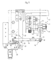
- This bond head 11 comprises a bond tool 12, which is also referred to as a "wedge capillary". Because of this Bond tool 12 extends a not shown Bond wire, in particular aluminum wire 13 therethrough.
- the bond tool 12 is at the free end of an ultrasound exciter or "Transducers" 14 arranged. The transducer is in the bond wire feed direction upstream of a wire tear-off clip 15. Because it the aforementioned components are generally known construction elements acts, is here for a more detailed description the same waived.
- the lower free end of the bond wire, not shown 13 or the bond wire tip is a device 16 for Formation of a "ball” 17 (see FIGS. 3 and 4) at the free end assigned to the bond wire 13.
- the formation of the "ball” the bond wire tip occurs immediately before the same is welded on on an assigned and not shown here Bond location.
- the mentioned facility for training a "Balls" comprises a so-called flame lance 18, which is at the free End of a holding arm pivoted in the horizontal plane 19 is attached.
- the holding arm 19 together with the flame lance 18 is on a separate stationary machine part 20 by one parallel to the direction of movement 10 of the bond tool 12 or of the bond head 11 extending axis 21 pivotable stored.
- the control arm 22 On the bondhead 11 is also parallel to Direction of movement 10 of the same extending control arm 22 attached, in the direction parallel to the direction of movement 10 adjustable.
- the control arm 22 has on the bondhead fastening section an elongated hole 23 through which a fastening screw 24 extends through. That of the bond office facing lower end of the control arm 22 is wedge-shaped formed showing an oblique to the direction of movement 10 of the bond head 11 extending control surface 25.
- control surface 25 of the control arm 22 When lowering the bondhead 11 with appropriate entrainment of the bond tool 12 comes the control surface 25 of the control arm 22 in contact with a roller 27 which is horizontally displaceable mounted carriage 26 is rotatably supported, wherein the roller axis is perpendicular to the direction of movement 10 of the Bond head and parallel to the control surface 25 of the control arm 22 extends.
- the control surface 25 pushes through the aforementioned contact with the roller 27 to the side of the slide 26, namely in 1 and 2 to the left while taking a another roller 29 on the carriage 26 about a vertical axis is rotatably mounted and abuts a driver 30, the fixed with the support arm 19 and then pivoted with this connected is.
- bond sites are also within one pot-shaped housing accessible, even if this is located near the housing wall.
- the forced control described between bond head 11 and flame lance 18 or their holding arm 19 enables a particularly simple construction.
- the return movement of the holding arm 19 together with the flame lance 18 is carried out by a Torsion spring, which is not shown here.
- This torsion spring is effective about the pivot axis 21 of the holding arm 19.
- a helical compression or tension spring can also be used serve as a reset element.
- the pivotal movement of the driver 30 due to the Hinund The movement of the roller 29 is indicated by the double arrow 31.
- This pivoting movement is followed equally by the holding arm 19 due to the rigid connection between driver 30 and Holding arm 19, the driver 30 in the illustrated Embodiment extends perpendicular to the support arm 19, namely at the level of the pivot axis 21 of the holding arm 19.
- the mentioned Back and forth movement of the interacting with the driver 30 Roll 29 is indicated in Fig. 2 with the double arrow 32.
- the Double arrow 32 of course also corresponds to the back and forth movement of the carriage 26 due to the up and down movement the control arm 22, the up and down movement 10 of the bondhead 11 follows.
- the flame lance 18 is enlarged Scale shown in longitudinal and cross section.
- the flame lance includes a cross section (Fig. 4) L-shaped section.
- Fig. 4 L-shaped section.
- the two legs of the L-shaped section limited space 33 emerges for the purpose of Formation of a "ball" on the bond wire tip this one, so as shown in Figs. 3 and 4.
- a flat electrode 34 arranged, the 35 via a clamping and contact screw is connected to an electrical line 36.
- the electrical Line 36 leads to a power source, not shown.
- the clamping and contact screw 35 also serves for fixation the flat electrode 34 on the top of the horizontal leg the flame lance 18, as indicated in FIG. 3 is.
- the horizontal leg of the flame lance 18 is shown in FIG. 3 and 4 with the reference numeral 39, while the vertical leg has the reference numeral 40.
- the flame lance 18 On the vertical leg 40 opposite side is the flame lance 18 open. Accordingly, the flame lance 18 can freely 1 and 2 described horizontal pivoting movement carry out without the flame lance beforehand for this purpose lowered or the wire tip can be raised with "Ball" 17 got to.
- the device described is particularly suitable for "Ball" bonding of thick aluminum wire. It should be borne in mind that previously a "ball” bonding with aluminum wire in normal Manufacturing company did not consider possible. By rapid oxidation of the wire tip when forming a “Balls” tends to detach it before hitting a bond can be pressed. The tip of the wire is literally burning from. Since according to the invention the formation of the "ball” 17 in in an inert gas environment, however, is the aluminum wire become controllable. This applies in particular to thick aluminum wire, but of course also for thin aluminum wire.
Landscapes
- Engineering & Computer Science (AREA)
- Mechanical Engineering (AREA)
- Wire Bonding (AREA)
Claims (7)
- Appareil pour réaliser des connexions en "boule" avec un capillaire de connexion, en particulier un capillaire de coin (12), dans lequel passe un fil de connexion (13), en particulier un fil de connexion en aluminium, qui peut être approché ou écarté de points de connexion, et avec un dispositif (16) pour former une boule (17) à l'extrémité libre du fil de connexion (13) avant la soudure de celui-ci en un point de connexion affecté, dans lequel le dispositif (16) pour former une "boule" (17) avec le capillaire de coin (12), respectivement une tête de connexion (11) qui le porte est couplé mécaniquement de manière telle que lors de l'abaissement du capillaire de coin (12), respectivement de la tête de connexion (11) affectée, il puisse sortir par pivotement dans un plan horizontal de sa position de formation de boule en une position de connexion,
caractérisé en ce que
le dispositif (16) pour former une "boule" (17) comprend une lance de flambage (18), dont la surface de section orientée vers la direction de pivotement du dispositif (16) est en forme de L. - Appareil selon la revendication 1,
caractérisé en ce que la sortie par pivotement du dispositif (16) pour former une "boule" (17) de la position de formation de "boule" s'effectue contre l'effet d'un élément élastique de repositionnement, en particulier d'un ressort de torsion. - Appareil selon la revendication 1 ou 2,
caractérisé en ce que, à la tête de connexion (11) qu'il est possible d'approcher et écarter conjointement avec le capillaire de connexion (12), un bras de guidage (22) est disposé s'étendant parallèlement à la direction du mouvement (10) avec à une extrémité, en particulier l'extrémité inférieure dirigée vers le point de connexion, des surfaces de guidage (25) formées qui, directement ou indirectement, agit conjointement avec un bras support (19) pivotant autour d'un axe (21) s'étendant également parallèlement à la direction du mouvement (10) de la tête de connexion (11), à l'extrémité libre duquel le dispositif (16) pour former une "boule" (17) est disposé. - Appareil selon la revendication 3,
caractérisé en ce que le bras de guidage (22) est décalable dans la direction du mouvement (10) de la tête de connexion (11), respectivement dans la direction parallèle à son allongement maximal. - Appareil selon la revendication 3 ou 4,
caractérisé en ce que la surface de guidage (25) du bras de guidage (22) agit conjointement avec un traíneau positionné de manière translatable en travers de son allongement longitudinal, qui, lors d'une translation hors d'une position d'origine déclenche le mouvement de pivotement du bras support (19) pour le dispositif (16) pour former une "boule" (17). - Appareil selon l'une des revendications 1 à 5,
caractérisé en ce que la lance de flambage (18) présente une électrode (34) raccordable à une source de courant. - Appareil selon la revendication 6,
caractérisé en ce que dans la zone entre les deux montants (39, 40) de la lance de flambage (18) débouche une ouverture (37) pour apporter du gaz inerte, en particulier de l'argon.
Applications Claiming Priority (4)
| Application Number | Priority Date | Filing Date | Title |
|---|---|---|---|
| DE19617360 | 1996-04-30 | ||
| DE19617360 | 1996-04-30 | ||
| DE19618320 | 1996-05-07 | ||
| DE19618320A DE19618320A1 (de) | 1996-04-30 | 1996-05-07 | Vorrichtung zum "Ball"-Bonden |
Publications (2)
| Publication Number | Publication Date |
|---|---|
| EP0804994A1 EP0804994A1 (fr) | 1997-11-05 |
| EP0804994B1 true EP0804994B1 (fr) | 2002-09-04 |
Family
ID=26025269
Family Applications (1)
| Application Number | Title | Priority Date | Filing Date |
|---|---|---|---|
| EP97102219A Expired - Lifetime EP0804994B1 (fr) | 1996-04-30 | 1997-02-12 | Dispositif de jonction par bille |
Country Status (2)
| Country | Link |
|---|---|
| EP (1) | EP0804994B1 (fr) |
| AT (1) | ATE223276T1 (fr) |
Family Cites Families (2)
| Publication number | Priority date | Publication date | Assignee | Title |
|---|---|---|---|---|
| JPS60227432A (ja) * | 1984-04-26 | 1985-11-12 | Nec Corp | ボンデイング用ワイヤのボ−ル形成装置 |
| GB9100225D0 (en) * | 1991-01-05 | 1991-02-20 | Emhart Inc | Bonding head |
-
1997
- 1997-02-12 AT AT97102219T patent/ATE223276T1/de not_active IP Right Cessation
- 1997-02-12 EP EP97102219A patent/EP0804994B1/fr not_active Expired - Lifetime
Also Published As
| Publication number | Publication date |
|---|---|
| EP0804994A1 (fr) | 1997-11-05 |
| ATE223276T1 (de) | 2002-09-15 |
Similar Documents
| Publication | Publication Date | Title |
|---|---|---|
| DE10337785B3 (de) | Düsenanpressvorrichtung | |
| EP0000876B1 (fr) | Appareil de soudage par points pour le soudage électrique par résistance, notamment pour le soudage de précision d'éléments miniatures | |
| DE2717453C3 (de) | Vorrichtung zum Widerstandsschweißen von Bauteilen | |
| DE2709435A1 (de) | Einbaubohle fuer strassendeckenfertiger | |
| EP0850705A1 (fr) | Machine à dresser | |
| AT403812B (de) | Maschine zum anpressen von schwellenankern | |
| EP0804994B1 (fr) | Dispositif de jonction par bille | |
| EP0904907B1 (fr) | Scie à fil à rouleau de stockage du fil de sciage | |
| DE4311299C1 (de) | Richtapparat für drahtförmiges, mehrdrahtförmiges oder rohrförmiges Richtgut | |
| DE3840006C1 (fr) | ||
| DE4326478C2 (de) | Bondkopf für Ultraschall-Bonden | |
| DE19618320A1 (de) | Vorrichtung zum "Ball"-Bonden | |
| DE10325351B4 (de) | Fronthaubenanordnung | |
| DE3049480C2 (de) | Vorrichtung zum Holzspalten mit Hilfe einer Drallkeilspitze | |
| DE3314646C2 (de) | Vorrichtung zum Widerstandsschweißen | |
| DE4117947A1 (de) | Hydromechanische ueberlastsicherung fuer beet- und drehpfluege | |
| EP1008550B1 (fr) | Agencement mécanique pour limiter le mouvement de plate-formes de travail | |
| EP1366947B1 (fr) | Dispositif de descente rapide d'une prise de courant | |
| DE3519594A1 (de) | Bondkopf | |
| DE69903007T2 (de) | Untertischkreissäge | |
| DE3807076C2 (fr) | ||
| EP0502254B1 (fr) | Outil interceps réversible | |
| DE19920919A1 (de) | Aufhängung für einen Ultraschall-Transducer und Verfahren zur Steuerung des Bondvorganges | |
| DE3915979A1 (de) | Vorrichtung zum einfaedeln von baendern, insbesondere metallbaendern, in bandbehandlungsanlagen | |
| DE4302421A1 (de) | Zweistöckige Parkeinrichtung |
Legal Events
| Date | Code | Title | Description |
|---|---|---|---|
| PUAI | Public reference made under article 153(3) epc to a published international application that has entered the european phase |
Free format text: ORIGINAL CODE: 0009012 |
|
| AK | Designated contracting states |
Kind code of ref document: A1 Designated state(s): AT CH DE FR GB IT LI NL |
|
| 17P | Request for examination filed |
Effective date: 19980429 |
|
| 17Q | First examination report despatched |
Effective date: 20000228 |
|
| GRAG | Despatch of communication of intention to grant |
Free format text: ORIGINAL CODE: EPIDOS AGRA |
|
| GRAG | Despatch of communication of intention to grant |
Free format text: ORIGINAL CODE: EPIDOS AGRA |
|
| GRAH | Despatch of communication of intention to grant a patent |
Free format text: ORIGINAL CODE: EPIDOS IGRA |
|
| GRAH | Despatch of communication of intention to grant a patent |
Free format text: ORIGINAL CODE: EPIDOS IGRA |
|
| GRAA | (expected) grant |
Free format text: ORIGINAL CODE: 0009210 |
|
| AK | Designated contracting states |
Kind code of ref document: B1 Designated state(s): AT CH DE FR GB IT LI NL |
|
| REF | Corresponds to: |
Ref document number: 223276 Country of ref document: AT Date of ref document: 20020915 Kind code of ref document: T |
|
| REG | Reference to a national code |
Ref country code: GB Ref legal event code: FG4D Free format text: NOT ENGLISH |
|
| REG | Reference to a national code |
Ref country code: CH Ref legal event code: NV Representative=s name: TROESCH SCHEIDEGGER WERNER AG Ref country code: CH Ref legal event code: EP |
|
| REF | Corresponds to: |
Ref document number: 59708101 Country of ref document: DE Date of ref document: 20021010 |
|
| GBT | Gb: translation of ep patent filed (gb section 77(6)(a)/1977) |
Effective date: 20021029 |
|
| ET | Fr: translation filed | ||
| PLBE | No opposition filed within time limit |
Free format text: ORIGINAL CODE: 0009261 |
|
| STAA | Information on the status of an ep patent application or granted ep patent |
Free format text: STATUS: NO OPPOSITION FILED WITHIN TIME LIMIT |
|
| 26N | No opposition filed |
Effective date: 20030605 |
|
| PGFP | Annual fee paid to national office [announced via postgrant information from national office to epo] |
Ref country code: AT Payment date: 20040220 Year of fee payment: 8 |
|
| PGFP | Annual fee paid to national office [announced via postgrant information from national office to epo] |
Ref country code: GB Payment date: 20050128 Year of fee payment: 9 |
|
| PG25 | Lapsed in a contracting state [announced via postgrant information from national office to epo] |
Ref country code: IT Free format text: LAPSE BECAUSE OF NON-PAYMENT OF DUE FEES;WARNING: LAPSES OF ITALIAN PATENTS WITH EFFECTIVE DATE BEFORE 2007 MAY HAVE OCCURRED AT ANY TIME BEFORE 2007. THE CORRECT EFFECTIVE DATE MAY BE DIFFERENT FROM THE ONE RECORDED. Effective date: 20050212 Ref country code: AT Free format text: LAPSE BECAUSE OF NON-PAYMENT OF DUE FEES Effective date: 20050212 |
|
| PGFP | Annual fee paid to national office [announced via postgrant information from national office to epo] |
Ref country code: FR Payment date: 20050216 Year of fee payment: 9 |
|
| PG25 | Lapsed in a contracting state [announced via postgrant information from national office to epo] |
Ref country code: GB Free format text: LAPSE BECAUSE OF NON-PAYMENT OF DUE FEES Effective date: 20060212 |
|
| GBPC | Gb: european patent ceased through non-payment of renewal fee |
Effective date: 20060212 |
|
| REG | Reference to a national code |
Ref country code: FR Ref legal event code: ST Effective date: 20061031 |
|
| PG25 | Lapsed in a contracting state [announced via postgrant information from national office to epo] |
Ref country code: FR Free format text: LAPSE BECAUSE OF NON-PAYMENT OF DUE FEES Effective date: 20060228 |
|
| PGFP | Annual fee paid to national office [announced via postgrant information from national office to epo] |
Ref country code: CH Payment date: 20080229 Year of fee payment: 12 |
|
| PGFP | Annual fee paid to national office [announced via postgrant information from national office to epo] |
Ref country code: NL Payment date: 20080227 Year of fee payment: 12 |
|
| REG | Reference to a national code |
Ref country code: CH Ref legal event code: PL |
|
| PG25 | Lapsed in a contracting state [announced via postgrant information from national office to epo] |
Ref country code: LI Free format text: LAPSE BECAUSE OF NON-PAYMENT OF DUE FEES Effective date: 20090228 Ref country code: CH Free format text: LAPSE BECAUSE OF NON-PAYMENT OF DUE FEES Effective date: 20090228 |
|
| NLV4 | Nl: lapsed or anulled due to non-payment of the annual fee |
Effective date: 20090901 |
|
| PG25 | Lapsed in a contracting state [announced via postgrant information from national office to epo] |
Ref country code: NL Free format text: LAPSE BECAUSE OF NON-PAYMENT OF DUE FEES Effective date: 20090901 |
|
| PGFP | Annual fee paid to national office [announced via postgrant information from national office to epo] |
Ref country code: DE Payment date: 20140429 Year of fee payment: 18 |
|
| REG | Reference to a national code |
Ref country code: DE Ref legal event code: R119 Ref document number: 59708101 Country of ref document: DE |
|
| PG25 | Lapsed in a contracting state [announced via postgrant information from national office to epo] |
Ref country code: DE Free format text: LAPSE BECAUSE OF NON-PAYMENT OF DUE FEES Effective date: 20150901 |