EP0804975B1 - Dispositif d'accumulation de courrier - Google Patents
Dispositif d'accumulation de courrier Download PDFInfo
- Publication number
- EP0804975B1 EP0804975B1 EP97107319A EP97107319A EP0804975B1 EP 0804975 B1 EP0804975 B1 EP 0804975B1 EP 97107319 A EP97107319 A EP 97107319A EP 97107319 A EP97107319 A EP 97107319A EP 0804975 B1 EP0804975 B1 EP 0804975B1
- Authority
- EP
- European Patent Office
- Prior art keywords
- conveying
- belt
- mail items
- output
- stream forming
- Prior art date
- Legal status (The legal status is an assumption and is not a legal conclusion. Google has not performed a legal analysis and makes no representation as to the accuracy of the status listed.)
- Expired - Lifetime
Links
- 230000001360 synchronised effect Effects 0.000 claims description 4
- 230000000717 retained effect Effects 0.000 claims description 2
- 230000001276 controlling effect Effects 0.000 claims 1
- 230000001105 regulatory effect Effects 0.000 claims 1
- 230000003287 optical effect Effects 0.000 description 4
- 239000002184 metal Substances 0.000 description 2
- 238000000034 method Methods 0.000 description 1
- 230000005693 optoelectronics Effects 0.000 description 1
- 230000000284 resting effect Effects 0.000 description 1
Images

Classifications
-
- B—PERFORMING OPERATIONS; TRANSPORTING
- B65—CONVEYING; PACKING; STORING; HANDLING THIN OR FILAMENTARY MATERIAL
- B65H—HANDLING THIN OR FILAMENTARY MATERIAL, e.g. SHEETS, WEBS, CABLES
- B65H29/00—Delivering or advancing articles from machines; Advancing articles to or into piles
- B65H29/66—Advancing articles in overlapping streams
- B65H29/6645—Advancing articles in overlapping streams buffering an overlapping stream of articles
-
- B—PERFORMING OPERATIONS; TRANSPORTING
- B07—SEPARATING SOLIDS FROM SOLIDS; SORTING
- B07C—POSTAL SORTING; SORTING INDIVIDUAL ARTICLES, OR BULK MATERIAL FIT TO BE SORTED PIECE-MEAL, e.g. BY PICKING
- B07C1/00—Measures preceding sorting according to destination
- B07C1/02—Forming articles into a stream; Arranging articles in a stream, e.g. spacing, orientating
- B07C1/025—Devices for the temporary stacking of objects provided with a stacking and destacking device (interstack device)
-
- Y—GENERAL TAGGING OF NEW TECHNOLOGICAL DEVELOPMENTS; GENERAL TAGGING OF CROSS-SECTIONAL TECHNOLOGIES SPANNING OVER SEVERAL SECTIONS OF THE IPC; TECHNICAL SUBJECTS COVERED BY FORMER USPC CROSS-REFERENCE ART COLLECTIONS [XRACs] AND DIGESTS
- Y10—TECHNICAL SUBJECTS COVERED BY FORMER USPC
- Y10S—TECHNICAL SUBJECTS COVERED BY FORMER USPC CROSS-REFERENCE ART COLLECTIONS [XRACs] AND DIGESTS
- Y10S209/00—Classifying, separating, and assorting solids
- Y10S209/90—Sorting flat-type mail
-
- Y—GENERAL TAGGING OF NEW TECHNOLOGICAL DEVELOPMENTS; GENERAL TAGGING OF CROSS-SECTIONAL TECHNOLOGIES SPANNING OVER SEVERAL SECTIONS OF THE IPC; TECHNICAL SUBJECTS COVERED BY FORMER USPC CROSS-REFERENCE ART COLLECTIONS [XRACs] AND DIGESTS
- Y10—TECHNICAL SUBJECTS COVERED BY FORMER USPC
- Y10S—TECHNICAL SUBJECTS COVERED BY FORMER USPC CROSS-REFERENCE ART COLLECTIONS [XRACs] AND DIGESTS
- Y10S209/00—Classifying, separating, and assorting solids
- Y10S209/923—Feed through including at least one endless conveyor
Definitions
- the present invention relates to a mail accumulating device.
- Mail sorting systems are known to comprise automatic reading devices supplied with a stream of mail items (letters and postcards), and which provide for automatically reading the address on the item, extracting any items with addresses not recognizable automatically, and supplying them to an accumulating device where the items are stored pending manual recognition of the address.
- Known accumulating devices which normally store the items in containers into which the items are fed successively, are not very flexible, at times involve a certain amount of manual operation (e.g. to transport and/or unload the containers), and therefore provide for a poor degree of efficiency.
- Document US-A-5 433 325 describes a device for accumulating mail items as defined in the preamble of claim 1.
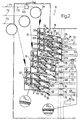
- Number 1 in Figure 1 indicates a mail sorting system comprising a mail accumulating device 5 supplied with mail items from an automatic reading device 6 (shown schematically) in turn supplied with a stream Fi of mail items 7 (letters and postcards), and which provides for automatically reading the handwritten or typed address on the item.
- Automatic reading device 6 generates at the output a first stream Fr of items with automatically recognized addresses; and a second stream Fnr of items bearing addresses which have failed to be recognized automatically, and which is conveniently supplied to accumulating device 5 where the items are stored pending manual recognition of the address.
- Accumulating device 5 and automatic reading device 6 are controlled by an electronic control unit 8 (shown schematically).
- Accumulating device 5 receives three separate streams F1, F2, F3 of mail items forming part of stream Fnr, and generates at the output a stream Fu of overlapping mail items, which is supplied, for example, to a separating device 9 (shown schematically) connected to accumulating device 5 by a conveyor belt system 10 (shown schematically).
- the accumulating device comprises an input section 11 receiving streams F1, F2, F3; an output section 12 generating stream Fu; and an intermediate accumulating section 14 interposed between input section 11 and output section 12.
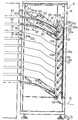
- Input section 11 comprises a vertical metal supporting structure 16 (shown schematically in Figure 1) supporting three superimposed stream forming devices 18, 19, 20 supplied respectively with streams F1, F2, F3. More specifically, stream F1 travels along a horizontal portion 22 ( Figure 2) of input section 11, and is then diverted downwards towards forming device 18 by a pulley 24 supporting two superimposed belts (not shown) for retaining the items in stream F1. Stream F1 is thus supplied to a sorting unit 26 forming part of forming device 18, and which directs the items in stream F1 to first, second, third and fourth stream forming units 27a, 27b, 27c, 27d.
- Sorting unit 26 is of a known type, and comprises first, second, third and fourth blade selecting devices 30a, 30b, 30c, 30d connected respectively to stream forming units 27a, 27b, 27c, 27d and aligned in a vertical direction parallel to stream F1 inside sorting unit 26.
- Each blade selecting device 30a, 30b, 30c, 30d is moved by a respective electric actuator (not shown) between a first activated position, to intercept and feed the items in stream F1 to a respective stream forming unit 27a, 27b, 27c, 27, and a second release position enabling the items to travel on to the next selecting device.
- Each blade selecting device 30a, 30b, 30c, 30d cooperates with a pair of powered rollers 31a, 31b located to the side of the blade selecting device, between this and the respective forming unit.
- Each stream forming unit 27 is fitted to a substantially rectangular metal plate 32, and comprises a first belt 35 defining an endless path extending between two pulleys 37, 38 located close to adjacent corners of plate 32 and cooperating with the inner surface of belt 35.
- Belt 35 also cooperates with two tensioning pulleys 39, 40 located along a first long side 32a of plate 32, and which press on the outer surface of belt 35 to form a substantially straight portion 42 of belt 35 extending between pulley 37 and pulley 38.
- Sorting unit 26 also comprises a second belt 44 defining an endless path, and the inner surface of which cooperates with two pulleys 46, 47 located along a second long side 32b of plate 32, and with a third pulley 53 fitted to a first end of an arm 55, the second end of which is hinged to plate 32.
- Pulleys 46, 47 and 53 are substantially located at the vertices of an isosceles triangle, with pulley 53 adjacent to straight portion 42 of belt 35.
- the second belt 44 also cooperates with two tensioning pulleys 58, 59 located respectively on the second end of arm 55 and close to pulley 47, and which press on the outer surface of belt 44.
- Belt 44 defines, among other things, a straight portion 61 extending between pulleys 46 and 53 and terminating at a point Z at which belt 44 contacts straight portion 42, and which defines the input of stream forming unit 27.
- Belts 35 and 44 are operated by respective drive devices 62a, 62b (shown schematically) controlled by electronic unit 8, and which provide for moving belts 35 and 44 as described later on.
- Each stream forming unit 27 also comprises a first optoelectronic sensor 63, in turn comprising a photoemitting device (not shown) and a photoreceiving device (not shown) defining an optical path 65, which extends close to the point of contact Z of belts 35 and 44, and is interrupted by the entry of a mail item into stream forming unit 27.
- Each stream forming unit also comprises an output 68 defined by an end portion of belt 35 close to pulley 38.
- Stream Forming devices 19 and 20 are structured in exactly the same way as forming device 18 described above, except that devices 19 and 20 comprise three sorting units 26 and three stream forming units 27 as opposed to four, and each sorting unit 26 comprises three blade selecting devices 30.
- output 68 of each stream forming unit 27 of stream forming device 18 communicates with the input 71 of a first straight conveyor belt 73 forming part of accumulating section 14 and extending between two pulleys 76, 77, at least one of which is a drive pulley operated by drive means 80 controlled by electronic unit 8.
- Pulley 76 is located adjacent to and below pulley 38, so that the mail items coming off belt 35 are deposited on to belt 73; and belt 73 is moved by drive means 80 towards the output section in discrete steps S2 of predetermined length (e.g. 5 mm) and at constant speed.
- belt 73 comprises an output 82 communicating with the input 84 of a second straight conveyor belt 86 forming part of accumulating section 14 and extending between two pulleys 87, 88, at least one of which is a drive pulley operated by respective drive means (not shown) controlled by electronic unit 8.
- Pulley 87 is located adjacent to pulley 77, so that the mail items coming off belt 73 are deposited on to belt 86; and belt 86 is moved (in the same direction as belt 73) by the drive means (not shown) in steps S2 of predetermined length and synchronized with the steps of belt 73.
- Belt 86 comprises an output 90 communicating with the input 91 of a third straight conveyor belt 93 forming part of accumulating section 14 and extending between two pulleys 94, 95, at least one of which is a drive pulley operated by respective drive means (not shown) controlled by electronic unit 8.
- Pulley 94 is located adjacent to pulley 88, so that the mail items coming off belt 86 are deposited on to belt 93; and belt 93 is moved (in the same direction as belts 73 and 86) by the drive means (not shown) in steps S2 of predetermined length and synchronized with the steps of belts 73 and 86.
- stream forming units 27 of forming devices 19 and 20 also communicate with successive adjacent first, second and third belts structured and operating in exactly the same way as belts 73, 86 and 93.
- stream forming units 27 of stream forming device 18 ( Figure 2) cooperate with respective straight auxiliary belts 97, each interposed between output 68 of the forming unit and the input of first conveyor belt 73; and, similarly, stream forming units 27 of stream forming device 19 ( Figure 2) cooperate with respective straight auxiliary belts 98, each interposed between output 68 of the forming unit and the input of first conveyor belt 73.
- Auxiliary belts 97 and 98 move in successive steps S2 in time with the first, second and third conveyor belts.
- each belt 93 defines an output 102 communicating with the input 104 of a conveying device 106, which, among other things, comprises a rectangular chute-like blade 109 projecting from a vertical wall 111 of output section 12, and comprising a first top end portion 109a adjacent to pulley 95, and a second bottom end portion 109b.
- Blade 109 cooperates with a powered conveyor belt 110, which rests on the upper face of blade 109, from portion 109a to portion 109b, to define a conveying portion 110a, which terminates as belt 110 rotates about a pulley 110b adjacent to bottom end portion 109b.
- Belt 110 is also supported on a number of tensioning pulleys located beneath blade 109.
- Conveying device 106 also comprises a pressing device 112, which in turn comprises a straight arm 114 having a first end portion connected to an elastic system (not shown) fitted to wall 111, and a second end portion fitted with an idle pressure roller 116, which rests on an initial portion of belt 110 close to top end portion 109a.
- Conveying device 106 also comprises an end guide device 118 in turn comprising a belt 119 extending along an endless path defined by a number of pulleys 120. More specifically, belt 119 defines a straight portion 122 extending between a pulley 120 facing blade 109, and a point at which belt 119 contacts belt 110 close to bottom end portion 109b.
- the end guide device also comprises a tensioning device 124, in turn comprising a straight arm 125 having a first end portion connected to an elastic system (not shown) fitted to wall 111, and a second end portion fitted with an idle roller 120a for pressing belt 119 on to belt 110.
- a tensioning device 124 in turn comprising a straight arm 125 having a first end portion connected to an elastic system (not shown) fitted to wall 111, and a second end portion fitted with an idle roller 120a for pressing belt 119 on to belt 110.
- Conveying devices 106 cooperate with a transportation device comprising a conveying belt 129 extending along a substantially rectangular endless path comprising a straight vertical portion 129a extending adjacent to all the bottom end portions 109b of blades 109, between a top pulley 131 and a bottom pulley 132.
- Belt 129 is moved downwards, i.e.
- tensioning devices 135 located inside the rectangular perimeter of belt 129, and each comprising a straight arm 136 having a first end portion connected to an elastic device 136a, and a second end portion fitted with an idle roller 137 cooperating with an inner portion of belt 129 to push belt 129 towards belt 110 rotating about pulley 110b.
- Conveyor belt system 10 defines a path (curved in the Figure 1 embodiment, but which may also be straight) of a length L at least equal to the length l of first straight conveyor belt 73 (L ⁇ 1).
- the mail items in each of streams F1, F2, F3, e.g. stream F1 are fed to a sorting unit 26 of a forming device, e.g. stream forming device 18.
- a forming device e.g. stream forming device 18.
- the mail items are therefore fed to the first selecting device, which, in said first position, feeds the items into stream forming unit 27a. If the selecting device is set to the second position, the mail items are fed to the next selecting device 30b, in which the above operations are repeated to feed the items into stream forming unit 27b or to the next selecting device.
- the last selecting device 30d acts as a fixed guide, but which anyway provides for feeding the mail items into the adjacent stream forming unit 27d.
- the mail item When fed to a stream forming unit 27, the mail item slides along a lateral wall of the selecting device to rollers 31a, 31b, which grip the item and feed it to input Z of stream forming unit 27.
- the mail item travels along a parabolic trajectory, which intersects optical path 65 and terminates when the leading edge of the item is inserted between belts 35 and 44 with a small portion of the item beneath pulley 53.
- the interruption of optical path 65 is detected by electronic control unit 8, which activates drive devices 62a, 62b so that belts 35 and 44 move one step S1 of predetermined length, e.g. 10 mm, in the same direction and at constant speed, and the first item fed into stream forming unit 27 is positioned between belts 35 and 44 and fed by a length S1 towards output 68.
- Group Ibs therefore travels along first belt 73 on to second belt 86, and from there on to third belt 93, and engagement of belts 73, 86, 93 is detected by optical sensors (not shown) located at opposite ends of the belts.
- Belts 73, 86, 93 therefore act as an accumulating unit for housing the group Ibs of overlapping items formed by stream forming unit 27 and expelled from output 68; and the group Ibs formed in stream forming unit 27 gets longer as further items are fed into stream forming unit 27, and moves towards output 102 of the last belt (the third in the example shown).
- group Ibs As it is moved along by belt 110, group Ibs is engaged by pressure roller 116 of pressing device 112 to hold the items down; and, at the end of belt 110, group Ibs is fed beneath belt 119, which pushes the items towards vertical portion 129a where group Ibs makes a sharp turn and is fed vertically downwards by belt 129.
- group Ibs When unloaded off belt 129, group Ibs is fed on to conveyor belt system 10 to form the output stream Fu generated by accumulating device 5.
- first belt 73 which, as stated, is of a length 1 equal to or less than the length of system 10, has definitely been cleared.
- Device 5 therefore requires no manual operation, by virtue of conveying the mail items, forming groups Ibs of overlapping items, storing and conveying groups Ibs along intermediate section 14, and unloading groups Ibs fully automatically, and is therefore highly flexible, and provides for a high degree of efficiency.
- the accumulating device may comprise a scanning device 140 (shown schematically) located along horizontal portion 22 to measure (in known manner, e.g. by means of laser techniques) the Dop thickness of individual mail items 7 supplied to forming device 18; and the Dop thickness value may conveniently be supplied to electronic control unit 8 to so control drive devices 62a, 62b as to regulate step S1 according to the measured Dop thickness, and so obtain a group Ibs of substantially constant thickness.
- a scanning device 140 shown schematically located along horizontal portion 22 to measure (in known manner, e.g. by means of laser techniques) the Dop thickness of individual mail items 7 supplied to forming device 18; and the Dop thickness value may conveniently be supplied to electronic control unit 8 to so control drive devices 62a, 62b as to regulate step S1 according to the measured Dop thickness, and so obtain a group Ibs of substantially constant thickness.
- output section 12 may comprise two outputs to increase the number of mail items unloaded per unit of time off accumulating device 5.
Landscapes
- Engineering & Computer Science (AREA)
- Mechanical Engineering (AREA)
- Sorting Of Articles (AREA)
- Delivering By Means Of Belts And Rollers (AREA)
- Separation, Sorting, Adjustment, Or Bending Of Sheets To Be Conveyed (AREA)
- Container Filling Or Packaging Operations (AREA)
Claims (18)
- Dispositif pour accumuler des éléments de courrier, comprenant un certain nombre d'unités de formation de flux (27) recevant chacune un flux (F1, F2, F3) d'éléments de courrier (7) ; chaque unité de formation de flux (27) comprenant des moyens de bande transporteuse (35, 44) et des premiers moyens d'entraínement (62a, 62b) qui déplacent lesdits moyens de bande transporteuse (35, 44) selon des pas discrets (S1) à réception d'un signal de validation ;
lesdites unités de formation de flux (27) retenant les éléments de courrier fournis à l'unité de formation de flux et délivrant les éléments de courrier retenus le long d'un trajet (42) s'étendant entre une entrée (Z) et une sortie (68) de ladite unité de formation de flux (27) ;
chaque unité formation de flux (27) comprenant également des moyens capteurs (63) pour détecter le passage d'un élément de courrier (7) dans l'unité de formation de flux et pour générer ledit signal de validation qui active lesdits premiers moyens d'entraínement (62a, 62b) déplaçant les éléments contenus dans ladite unité de formation de flux de ladite entrée (Z) à ladite sortie (68) selon lesdits pas discrets (S1), formant ainsi un groupe (Ibs) d'éléments de courrier en recouvrement alignés le long desdits moyens de bande transporteuse (35, 44) ayant des bords avant respectifs séparés d'une distance donnée (S1) ;
caractérisé en ce qu'il comprend un certain nombre de dispositifs de transport (73, 86, 93)déplacés par des seconds moyens d'entraínement (80) ; chaque dispositif de transport (73, 86, 93) ayant une entrée (71), une sortie (102) et définissant une unité d'accumulation pour un groupe (Ibs) d'éléments de courrier en recouvrement se déplaçant le long du dispositif de transport ;
l'entrée (71) de chaque dispositif de transport (73, 86, 93) communiquant avec une sortie respective (68) d'une unité de formation de flux respective (27) pour recevoir ledit groupe (Ibs) d'éléments de courrier en recouvrement et pour délivrer ledit groupe (Ibs) d'éléments de courrier en recouvrement à la sortie (102) dudit dispositif de transport (73, 86, 93). - Dispositif selon la revendication 1, caractérisé en ce que chaque dispositif de transport comprend au moins une bande transporteuse (73, 86, 93)déplacée par lesdits seconds moyens d'entraínement (80) ayant une entrée (71) communiquant avec une sortie respective (68) de l'une desdites unités de formation de flux (27).
- Dispositif selon l'une des revendications 1 et 2, caractérisé en ce que chaque dispositif de transport comprend un certain nombre de bandes transporteuses (73, 86, 93) agencées en série etdéplacées dans la même direction par lesdits seconds moyens d'entraínement (80) ; une première bande transporteuse dudit certain nombre ayant une entrée (71) communiquant avec une sortie respective (68) de ladite unité de formation de flux (27).
- Dispositif selon l'une quelconque des revendications précédentes, caractêrisé en ce que chaque dispositif de transport (73, 86, 93) estdéplacé selon des pas discrets successifs (S2) commandés par lesdits seconds moyens d'entraínement (80).
- Dispositif selon la revendication 4, caractérisé en ce que lesdits seconds moyens d'entraínement déplacent ledit dispositif de transport selon des pas discrets (S2) synchronisés avec lesdits pas discrets (S1) selon lequel lesdits moyens de bandes transporteuses (35, 44) sontdéplacés par lesdits premiers moyens d'entraínement (62a, 62b).
- Dispositif selon l'une quelconque des revendications précédentes, caractérisé en ce que lesdits premiers moyens d'entraínement (62a, 62b) déplacent lesdits moyens de bande transporteuse (35, 44) selon des premiers pas discrets (S1), et lesdits dispositifs de transport (73, 86, 93) sontdéplacés par lesdits seconds moyens d'entraínement (80) selon des seconds pas discrets (S2) ; lesdits seconds pas discrets (S2) étant plus petits que lesdits premiers pas discrets (S1).
- Dispositif selon l'une quelconque des revendications précédentes, caractérisé en ce que les moyens de bande transporteuse (35, 44) comprennent au moins une première bande (35) et une seconde bande (44) activée par des moyens d'entraínement respectifs (62a, 62b) ;
ladite première bande (35) comprenant au moins une partie sensiblement rectiligne (42) définissant au moins une partie dudit trajet ; ladite seconde bande (44) comprenant une partie (61) se terminant à un point de contact (Z) avec ladite partie sensiblement rectiligne (42) ; ledit point de contact (Z) définissant ladite entrée de ladite l'unité de formation de flux 27 ; et lesdites première et seconde bandes (35, 44) étantdéplacées dans la même direction et selon des pas discrets (S1) à réception dudit signal de validation. - Dispositif selon la revendication 7, caractérisé en ce que ladite seconde bande (44) est supportée par au moins trois poulies (46, 47, 53) placées aux sommets d'un triangle et coopérant avec une surface interne de ladite seconde bande ; une (53) desdites trois poulies étant ajustée sur une extrémité libre d'un bras (55) reliée à des moyens élastiques et pour presser ladite poulie (53) sur ladite partie sensiblement rectiligne de ladite première bande (35) pour définir ledit point de contact (Z).
- Dispositif selon l'une quelconque des revendications précédentes, caractérisé en ce qu'il comprend des moyens de tri (26) reliés auxdites unités de formation de flux (27) ; lesdits moyens de tri (26) recevant un flux (F1, F2, F3) d'éléments de courrier et dirigeant lesdits éléments de courrier vers les diverses unités de formation de flux (27).
- Dispositif selon la revendication 9, caractérisé en ce que les moyens de tri (26) comprennent un certain nombre de sélecteurs (30) pour intercepter successivement les éléments de courrier dans ledit flux ; chacun desdits sélecteurs (30) étant mobile entre une position activée pour intercepter et délivrer les éléments de courrier (7) dans ledit flux vers une unité de formation de flux (27) respective, et une position désactivée pour délivrer le flux des éléments de courrier vers le sélecteur suivant (30).
- Dispositif selon l'une quelconque des revendications précédentes, caractérisé en ce qu'il comprend une section de sortie (12) comprenant un dispositif de transport commun (129) ayant des entrées ; lesdites sorties (102) desdits dispositifs de transport (73, 86, 93) communiquant avec ladite entrée dudit dispositif de transport commun (129) pour recevoir lesdits groupes (Ibs) d'éléments de courrier en recouvrement desdits dispositifs de transport (73, 86, 93).
- Dispositif selon la revendication 11, caractérisé en ce que ladite section de sortie (12) comprend un certain nombre de moyens de transport (106), chacun interposé entre une sortie (102) d'un dispositif de transport (73, 86, 93) et ledit dispositif de transport commun (129).
- Dispositif selon la revendication 12, caractérisé en ce que chaque moyen de transport (106) comprend une lame du type goulotte (109) ayant une partie d'extrémité supérieure (109a) adjacente à ladite sortie (102) dudit dispositif de transport (73, 86, 93), une partie d'extrémité inférieure (109a) en regard d'une partie dudit dispositif de transport commun (129) ; ladite lame du type goulotte (109) étant raccordée à une première bande transporteuse motorisée (110) définissant une partie de transport (110a) s'étendant à proximité de ladite lame du type goulotte, de ladite partie d'extrémitê supérieure (109a) à ladite partie d'extrémité inférieure (109b).
- Dispositif selon la revendication 13, caractérisé en ce que chaque moyen de transport (106) comprend également un dispositif de pression en regard de ladite lame du type goulotte (109) ayant au moins un rouleau de pression libre (116) en contact avec ladite première bande transporteuse motorisée (110) à proximité de ladite partie d'extrémité supérieure (109a).
- Dispositif selon l'une des revendications 13 et 14, caractérisé en ce que chaque moyen de transport (106) comprend également un dispositif de guidage d'extrémité (118) comprenant à son tour une seconde bande transporteuse motorisée (119) définissant au moins une partie rectiligne (122) en regard de ladite lame du type goulotte (109) et en contact avec ladite première bande transporteuse motorisée (110) à proximité de ladite partie d'extrémité inférieure (109d) de ladite lame du type goulotte (109).
- Dispositif selon l'une des revendications 13 à 15, caractérisé en ce que ledit dispositif de transport commun comprend une troisième bande transporteuse motorisée (129) définissant au moins une partie rectiligne (129a) en regard desdites parties d'extrémité inférieure (109b) desdites lames du type goulotte (109).
- Dispositif selon l'une quelconque des revendications précédentes, caractérisé en ce qu'il comprend des moyens de mesure (140) mesurant l'épaisseur (Dop) d'éléments de courrier individuel (7) fournis aux unités de formation de flux (27) ; ledit dispositif d'accumulation (5) comprenant des moyens de commande électronique (8) commandant lesdits premiers moyens d'entraínement au moyen d'un signal de commande lié à ladite épaisseur mesurée (Dop) ; lesdits premiers moyens d'entraínement (62a, 62b) commandés par ledit signal de commande régulant la dimension desdits pas discrets (S1) selon l'épaisseur mesurée (Dop) pour obtenir un groupe (Ibs) d'éléments de courrier en recouvrement d'une épaisseur sensiblement constante.
- Dispositif selon l'une quelconque des revendications précédentes, caractérisé en ce que lesdits dispositifs de transport (73, 86, 93) communiquent à la sortie (102) avec un système de transport (10) s'étendant à partir dudit dispositif d'accumulation (5) et pour transporter les groupes (Ibs) d'éléments de courrier en recouvrement ;
chacun desdits dispositifs de transport (73, 86, 93) comprenant au moins une première partie de transport (73) communiquant à l'entrée (71) avec la sortie (68) de l'unité de formation de flux respectif (27) et une seconde partie de transport (86, 93) reliée en série à ladite première partie de transport (73) et ayant une sortie (102) définissant la sortie du dispositif de transport ; ledit système de transport (10) définissant un trajet d'une longueur (L) au moins égale à la longueur de ladite première partie de transport (73).
Applications Claiming Priority (2)
| Application Number | Priority Date | Filing Date | Title |
|---|---|---|---|
| IT96TO000358A IT1285082B1 (it) | 1996-05-03 | 1996-05-03 | Dispositivo di accumulo per oggetti postali. |
| ITTO960358 | 1996-05-03 |
Publications (3)
| Publication Number | Publication Date |
|---|---|
| EP0804975A2 EP0804975A2 (fr) | 1997-11-05 |
| EP0804975A3 EP0804975A3 (fr) | 1998-10-28 |
| EP0804975B1 true EP0804975B1 (fr) | 2002-11-13 |
Family
ID=11414602
Family Applications (1)
| Application Number | Title | Priority Date | Filing Date |
|---|---|---|---|
| EP97107319A Expired - Lifetime EP0804975B1 (fr) | 1996-05-03 | 1997-05-02 | Dispositif d'accumulation de courrier |
Country Status (5)
| Country | Link |
|---|---|
| US (1) | US5908116A (fr) |
| EP (1) | EP0804975B1 (fr) |
| JP (1) | JPH1071368A (fr) |
| DE (1) | DE69716990T2 (fr) |
| IT (1) | IT1285082B1 (fr) |
Cited By (1)
| Publication number | Priority date | Publication date | Assignee | Title |
|---|---|---|---|---|
| EP2366462A1 (fr) | 2010-03-19 | 2011-09-21 | ELSAG DATAMAT S.p.A. | Procédé et dispositif pour trier des objets postaux |
Families Citing this family (12)
| Publication number | Priority date | Publication date | Assignee | Title |
|---|---|---|---|---|
| ATE222212T1 (de) * | 1996-07-19 | 2002-08-15 | Ferag Ag | Vorrichtung zum zubringen von druckereierzeugnissen zu verarbeitungsstationen |
| IT1296655B1 (it) * | 1997-12-17 | 1999-07-14 | Finmeccanica Spa | Dispositivo di accumulo e trasporto di insiemi di oggetti postali parzialmente sovrapposti. |
| US6151037A (en) * | 1998-01-08 | 2000-11-21 | Zebra Technologies Corporation | Printing apparatus |
| US6536191B1 (en) * | 1999-06-28 | 2003-03-25 | Bell & Howell Mail And Messaging Technologies Company | Method and apparatus for high speed envelope traying |
| US8556260B2 (en) * | 2006-05-26 | 2013-10-15 | Lockheed Martin Corporation | Method for optimally loading objects into storage/transport containers |
| DE102007057497A1 (de) * | 2007-11-29 | 2009-06-10 | Siemens Ag | Verfahren und Vorrichtung zum Zusammenführen von zwei Strömen von Gegenständen |
| DE102007058581B4 (de) * | 2007-12-05 | 2011-03-24 | Siemens Ag | Sortiersystem für flache Postsendungen |
| IT1402221B1 (it) * | 2010-10-06 | 2013-08-28 | Elsag Datamat Spa | Sistema di movimentazione automatica per lettere alms |
| ITTO20110851A1 (it) * | 2011-09-23 | 2013-03-24 | Selex Elsag Spa | Metodo e dispositivo per la movimentazione e fusione di due o piu' gruppi di oggetti postali parzialmente sovrapposti (shingled) |
| WO2016077782A1 (fr) | 2014-11-13 | 2016-05-19 | United States Postal Service | Système et procédé de tri et de séquençage d'articles |
| WO2017192824A1 (fr) | 2016-05-06 | 2017-11-09 | United States Postal Service | Système et procédé de tri et de livraison d'articles |
| US10974283B2 (en) | 2017-10-05 | 2021-04-13 | United States Postal Service | System and method of sorting and sequencing items |
Family Cites Families (8)
| Publication number | Priority date | Publication date | Assignee | Title |
|---|---|---|---|---|
| US4161244A (en) * | 1978-03-31 | 1979-07-17 | Burroughs Corporation | Mail buffer feeder system |
| US4273326A (en) * | 1978-12-14 | 1981-06-16 | Norfin, Inc. | Collator |
| FR2650767B1 (fr) * | 1989-08-08 | 1991-12-06 | Rougier Yann | Dispositif d'indexation d'enveloppes de lettres ou objets plats analogues |
| NL8902846A (nl) * | 1989-11-17 | 1991-06-17 | Nederland Ptt | Buffer en buffersysteem voor het tijdelijk opslaan van platte voorwerpen, zoals brieven. |
| US5119954A (en) * | 1990-03-29 | 1992-06-09 | Bell & Howell Company | Multi-pass sorting machine |
| US5095684A (en) * | 1990-10-31 | 1992-03-17 | Food Machinery Sales, Inc. | On edge cookie loader |
| IT1256777B (it) * | 1992-01-22 | 1995-12-15 | Macchina con linea di ritardo per il trattamento di oggetti postali. | |
| ES2137219T3 (es) * | 1993-11-23 | 1999-12-16 | Elsag Spa | Dispositivo acumulador de correo. |
-
1996
- 1996-05-03 IT IT96TO000358A patent/IT1285082B1/it active IP Right Grant
-
1997
- 1997-05-02 JP JP9127787A patent/JPH1071368A/ja active Pending
- 1997-05-02 EP EP97107319A patent/EP0804975B1/fr not_active Expired - Lifetime
- 1997-05-02 US US08/850,380 patent/US5908116A/en not_active Expired - Lifetime
- 1997-05-02 DE DE69716990T patent/DE69716990T2/de not_active Expired - Lifetime
Cited By (1)
| Publication number | Priority date | Publication date | Assignee | Title |
|---|---|---|---|---|
| EP2366462A1 (fr) | 2010-03-19 | 2011-09-21 | ELSAG DATAMAT S.p.A. | Procédé et dispositif pour trier des objets postaux |
Also Published As
| Publication number | Publication date |
|---|---|
| IT1285082B1 (it) | 1998-06-03 |
| ITTO960358A1 (it) | 1997-11-03 |
| EP0804975A3 (fr) | 1998-10-28 |
| EP0804975A2 (fr) | 1997-11-05 |
| ITTO960358A0 (it) | 1996-05-03 |
| US5908116A (en) | 1999-06-01 |
| JPH1071368A (ja) | 1998-03-17 |
| DE69716990D1 (de) | 2002-12-19 |
| DE69716990T2 (de) | 2003-07-24 |
Similar Documents
| Publication | Publication Date | Title |
|---|---|---|
| US5433325A (en) | Mail accumulating device | |
| EP0804975B1 (fr) | Dispositif d'accumulation de courrier | |
| US4119194A (en) | System and apparatus for the orientation and bidirectional feed of indicia bearing mail | |
| US4753429A (en) | Collating station for inserting machine | |
| US5508818A (en) | Mixed mail transport | |
| US5547063A (en) | Apparatus and method of sorting objects | |
| WO2001046047A2 (fr) | Convoyeur a vitesse variable | |
| US8727341B2 (en) | Feeding apparatus for flat items processed in a mail sorting machine with pulleys located under transport deck | |
| CA1090737A (fr) | No translation available | |
| JP2001515002A (ja) | 給送装置 | |
| US5538140A (en) | Buffered stacker with drop floor assembly | |
| US8002263B2 (en) | Pickoff mechanism for mail feeder | |
| US5465825A (en) | Mail flow compensating device | |
| US7029225B2 (en) | Stacking tray for flat mail items | |
| US5330174A (en) | Automatic article discharge into mail container | |
| US5171008A (en) | Apparatus for stacking pieces of mail having a pressure roller | |
| US6179284B1 (en) | Method and apparatus for forming a scaled flow of overlapping shipments | |
| US4691913A (en) | Separating apparatus for flat objects | |
| US4802665A (en) | Conveyor device for flat objects | |
| US5569015A (en) | Intermediate storage apparatus | |
| JPH08239142A (ja) | 郵便物分離装置 | |
| US20020094266A1 (en) | Charging apparatus | |
| EP0876980B1 (fr) | Appareil d'alimentation en objets et de tri d'objets | |
| FI83571B (fi) | Behandlingsanordning foer flaskorna fraon en automat foer returflaskor och foerfarande foer sortering av returflaskor. | |
| JPH1085673A (ja) | 紙葉類処理装置 |
Legal Events
| Date | Code | Title | Description |
|---|---|---|---|
| PUAI | Public reference made under article 153(3) epc to a published international application that has entered the european phase |
Free format text: ORIGINAL CODE: 0009012 |
|
| AK | Designated contracting states |
Kind code of ref document: A2 Designated state(s): DE ES FR GB NL |
|
| PUAL | Search report despatched |
Free format text: ORIGINAL CODE: 0009013 |
|
| AK | Designated contracting states |
Kind code of ref document: A3 Designated state(s): DE ES FR GB NL |
|
| 17P | Request for examination filed |
Effective date: 19990212 |
|
| RAP1 | Party data changed (applicant data changed or rights of an application transferred) |
Owner name: ELSAG SPA |
|
| 17Q | First examination report despatched |
Effective date: 20010313 |
|
| GRAG | Despatch of communication of intention to grant |
Free format text: ORIGINAL CODE: EPIDOS AGRA |
|
| GRAG | Despatch of communication of intention to grant |
Free format text: ORIGINAL CODE: EPIDOS AGRA |
|
| GRAH | Despatch of communication of intention to grant a patent |
Free format text: ORIGINAL CODE: EPIDOS IGRA |
|
| GRAH | Despatch of communication of intention to grant a patent |
Free format text: ORIGINAL CODE: EPIDOS IGRA |
|
| GRAA | (expected) grant |
Free format text: ORIGINAL CODE: 0009210 |
|
| AK | Designated contracting states |
Kind code of ref document: B1 Designated state(s): DE ES FR GB NL |
|
| PG25 | Lapsed in a contracting state [announced via postgrant information from national office to epo] |
Ref country code: NL Free format text: LAPSE BECAUSE OF FAILURE TO SUBMIT A TRANSLATION OF THE DESCRIPTION OR TO PAY THE FEE WITHIN THE PRESCRIBED TIME-LIMIT Effective date: 20021113 |
|
| REG | Reference to a national code |
Ref country code: GB Ref legal event code: FG4D |
|
| REF | Corresponds to: |
Ref document number: 69716990 Country of ref document: DE Date of ref document: 20021219 |
|
| NLV1 | Nl: lapsed or annulled due to failure to fulfill the requirements of art. 29p and 29m of the patents act | ||
| PG25 | Lapsed in a contracting state [announced via postgrant information from national office to epo] |
Ref country code: GB Free format text: LAPSE BECAUSE OF NON-PAYMENT OF DUE FEES Effective date: 20030502 |
|
| PG25 | Lapsed in a contracting state [announced via postgrant information from national office to epo] |
Ref country code: ES Free format text: LAPSE BECAUSE OF FAILURE TO SUBMIT A TRANSLATION OF THE DESCRIPTION OR TO PAY THE FEE WITHIN THE PRESCRIBED TIME-LIMIT Effective date: 20030529 |
|
| ET | Fr: translation filed | ||
| PLBE | No opposition filed within time limit |
Free format text: ORIGINAL CODE: 0009261 |
|
| STAA | Information on the status of an ep patent application or granted ep patent |
Free format text: STATUS: NO OPPOSITION FILED WITHIN TIME LIMIT |
|
| 26N | No opposition filed |
Effective date: 20030814 |
|
| GBPC | Gb: european patent ceased through non-payment of renewal fee |
Effective date: 20030502 |
|
| PGFP | Annual fee paid to national office [announced via postgrant information from national office to epo] |
Ref country code: DE Payment date: 20130522 Year of fee payment: 17 |
|
| PGFP | Annual fee paid to national office [announced via postgrant information from national office to epo] |
Ref country code: FR Payment date: 20130610 Year of fee payment: 17 |
|
| REG | Reference to a national code |
Ref country code: DE Ref legal event code: R119 Ref document number: 69716990 Country of ref document: DE |
|
| REG | Reference to a national code |
Ref country code: DE Ref legal event code: R119 Ref document number: 69716990 Country of ref document: DE Effective date: 20141202 |
|
| REG | Reference to a national code |
Ref country code: FR Ref legal event code: ST Effective date: 20150130 |
|
| PG25 | Lapsed in a contracting state [announced via postgrant information from national office to epo] |
Ref country code: DE Free format text: LAPSE BECAUSE OF NON-PAYMENT OF DUE FEES Effective date: 20141202 |
|
| PG25 | Lapsed in a contracting state [announced via postgrant information from national office to epo] |
Ref country code: FR Free format text: LAPSE BECAUSE OF NON-PAYMENT OF DUE FEES Effective date: 20140602 |