EP0804684B1 - Compressor - Google Patents
Compressor Download PDFInfo
- Publication number
- EP0804684B1 EP0804684B1 EP95939216A EP95939216A EP0804684B1 EP 0804684 B1 EP0804684 B1 EP 0804684B1 EP 95939216 A EP95939216 A EP 95939216A EP 95939216 A EP95939216 A EP 95939216A EP 0804684 B1 EP0804684 B1 EP 0804684B1
- Authority
- EP
- European Patent Office
- Prior art keywords
- piston
- compressor according
- compressor
- working medium
- supply
- Prior art date
- Legal status (The legal status is an assumption and is not a legal conclusion. Google has not performed a legal analysis and makes no representation as to the accuracy of the status listed.)
- Expired - Lifetime
Links
- 238000007906 compression Methods 0.000 claims description 31
- 230000006835 compression Effects 0.000 claims description 30
- 230000033001 locomotion Effects 0.000 claims description 14
- 238000000034 method Methods 0.000 claims description 2
- 238000013461 design Methods 0.000 description 15
- 238000001816 cooling Methods 0.000 description 8
- 238000011161 development Methods 0.000 description 6
- 238000004939 coking Methods 0.000 description 4
- 238000002485 combustion reaction Methods 0.000 description 4
- 238000010276 construction Methods 0.000 description 4
- 238000004519 manufacturing process Methods 0.000 description 3
- 238000007789 sealing Methods 0.000 description 3
- 238000000926 separation method Methods 0.000 description 3
- 238000012549 training Methods 0.000 description 3
- 230000006978 adaptation Effects 0.000 description 2
- 238000009826 distribution Methods 0.000 description 2
- 238000010438 heat treatment Methods 0.000 description 2
- 238000009434 installation Methods 0.000 description 2
- 238000005461 lubrication Methods 0.000 description 2
- 239000002245 particle Substances 0.000 description 2
- 230000005540 biological transmission Effects 0.000 description 1
- 230000015572 biosynthetic process Effects 0.000 description 1
- 230000000694 effects Effects 0.000 description 1
- 239000012530 fluid Substances 0.000 description 1
- 239000007789 gas Substances 0.000 description 1
- 239000004575 stone Substances 0.000 description 1
- 238000003860 storage Methods 0.000 description 1
- 239000000126 substance Substances 0.000 description 1
- 238000012546 transfer Methods 0.000 description 1
- XLYOFNOQVPJJNP-UHFFFAOYSA-N water Substances O XLYOFNOQVPJJNP-UHFFFAOYSA-N 0.000 description 1
Images

Classifications
-
- F—MECHANICAL ENGINEERING; LIGHTING; HEATING; WEAPONS; BLASTING
- F02—COMBUSTION ENGINES; HOT-GAS OR COMBUSTION-PRODUCT ENGINE PLANTS
- F02B—INTERNAL-COMBUSTION PISTON ENGINES; COMBUSTION ENGINES IN GENERAL
- F02B75/00—Other engines
- F02B75/16—Engines characterised by number of cylinders, e.g. single-cylinder engines
- F02B75/18—Multi-cylinder engines
- F02B75/24—Multi-cylinder engines with cylinders arranged oppositely relative to main shaft and of "flat" type
- F02B75/246—Multi-cylinder engines with cylinders arranged oppositely relative to main shaft and of "flat" type with only one crankshaft of the "pancake" type, e.g. pairs of connecting rods attached to common crankshaft bearing
-
- F—MECHANICAL ENGINEERING; LIGHTING; HEATING; WEAPONS; BLASTING
- F01—MACHINES OR ENGINES IN GENERAL; ENGINE PLANTS IN GENERAL; STEAM ENGINES
- F01B—MACHINES OR ENGINES, IN GENERAL OR OF POSITIVE-DISPLACEMENT TYPE, e.g. STEAM ENGINES
- F01B9/00—Reciprocating-piston machines or engines characterised by connections between pistons and main shafts, not specific to groups F01B1/00 - F01B7/00
- F01B9/02—Reciprocating-piston machines or engines characterised by connections between pistons and main shafts, not specific to groups F01B1/00 - F01B7/00 with crankshaft
- F01B9/026—Rigid connections between piston and rod; Oscillating pistons
-
- F—MECHANICAL ENGINEERING; LIGHTING; HEATING; WEAPONS; BLASTING
- F04—POSITIVE - DISPLACEMENT MACHINES FOR LIQUIDS; PUMPS FOR LIQUIDS OR ELASTIC FLUIDS
- F04B—POSITIVE-DISPLACEMENT MACHINES FOR LIQUIDS; PUMPS
- F04B25/00—Multi-stage pumps
-
- F—MECHANICAL ENGINEERING; LIGHTING; HEATING; WEAPONS; BLASTING
- F04—POSITIVE - DISPLACEMENT MACHINES FOR LIQUIDS; PUMPS FOR LIQUIDS OR ELASTIC FLUIDS
- F04B—POSITIVE-DISPLACEMENT MACHINES FOR LIQUIDS; PUMPS
- F04B27/00—Multi-cylinder pumps specially adapted for elastic fluids and characterised by number or arrangement of cylinders
- F04B27/02—Multi-cylinder pumps specially adapted for elastic fluids and characterised by number or arrangement of cylinders having cylinders arranged oppositely relative to main shaft
-
- F—MECHANICAL ENGINEERING; LIGHTING; HEATING; WEAPONS; BLASTING
- F04—POSITIVE - DISPLACEMENT MACHINES FOR LIQUIDS; PUMPS FOR LIQUIDS OR ELASTIC FLUIDS
- F04B—POSITIVE-DISPLACEMENT MACHINES FOR LIQUIDS; PUMPS
- F04B39/00—Component parts, details, or accessories, of pumps or pumping systems specially adapted for elastic fluids, not otherwise provided for in, or of interest apart from, groups F04B25/00 - F04B37/00
- F04B39/0005—Component parts, details, or accessories, of pumps or pumping systems specially adapted for elastic fluids, not otherwise provided for in, or of interest apart from, groups F04B25/00 - F04B37/00 adaptations of pistons
- F04B39/0016—Component parts, details, or accessories, of pumps or pumping systems specially adapted for elastic fluids, not otherwise provided for in, or of interest apart from, groups F04B25/00 - F04B37/00 adaptations of pistons with valve arranged in the piston
-
- F—MECHANICAL ENGINEERING; LIGHTING; HEATING; WEAPONS; BLASTING
- F04—POSITIVE - DISPLACEMENT MACHINES FOR LIQUIDS; PUMPS FOR LIQUIDS OR ELASTIC FLUIDS
- F04B—POSITIVE-DISPLACEMENT MACHINES FOR LIQUIDS; PUMPS
- F04B39/00—Component parts, details, or accessories, of pumps or pumping systems specially adapted for elastic fluids, not otherwise provided for in, or of interest apart from, groups F04B25/00 - F04B37/00
- F04B39/04—Measures to avoid lubricant contaminating the pumped fluid
- F04B39/041—Measures to avoid lubricant contaminating the pumped fluid sealing for a reciprocating rod
-
- F—MECHANICAL ENGINEERING; LIGHTING; HEATING; WEAPONS; BLASTING
- F04—POSITIVE - DISPLACEMENT MACHINES FOR LIQUIDS; PUMPS FOR LIQUIDS OR ELASTIC FLUIDS
- F04B—POSITIVE-DISPLACEMENT MACHINES FOR LIQUIDS; PUMPS
- F04B39/00—Component parts, details, or accessories, of pumps or pumping systems specially adapted for elastic fluids, not otherwise provided for in, or of interest apart from, groups F04B25/00 - F04B37/00
- F04B39/12—Casings; Cylinders; Cylinder heads; Fluid connections
- F04B39/126—Cylinder liners
-
- Y—GENERAL TAGGING OF NEW TECHNOLOGICAL DEVELOPMENTS; GENERAL TAGGING OF CROSS-SECTIONAL TECHNOLOGIES SPANNING OVER SEVERAL SECTIONS OF THE IPC; TECHNICAL SUBJECTS COVERED BY FORMER USPC CROSS-REFERENCE ART COLLECTIONS [XRACs] AND DIGESTS
- Y10—TECHNICAL SUBJECTS COVERED BY FORMER USPC
- Y10T—TECHNICAL SUBJECTS COVERED BY FORMER US CLASSIFICATION
- Y10T74/00—Machine element or mechanism
- Y10T74/18—Mechanical movements
- Y10T74/18056—Rotary to or from reciprocating or oscillating
- Y10T74/18248—Crank and slide
- Y10T74/18256—Slidable connections [e.g., scotch yoke]
Definitions
- the invention relates to a compressor for the compression of a working medium, in particular for production of compressed air, with at least one in a work area reciprocating piston to compress the Working medium, a drive device for reciprocation of the piston and with a feed device and a discharge device for supplying or removing the working medium, a crank loop drive being provided as the drive device.
- Compressible substances such as gases are used as working media or vapors are used in conventional compressors mostly air is compressed. This compressed air is e.g. in trucks as a means of transmission in braking devices used.
- the conventional plunger compressors with crank-connecting rod drive therefore require a considerable constructive Effort, a variety of components and a large one Space requirements. Furthermore, e.g. a change of location of the Inlet connection usually a complete constructive redesign of the compressor, since the piping of the inlet and the outlet pipes and the cooling pipes precisely matched due to the heat development have to be.
- crank loop drives to use for internal combustion engines. So shows e.g. DE 32 18 311 C2 a crank loop drive, especially for a two-stroke internal combustion engine is provided which is operational even without oil lubrication is. Furthermore, DE 34 47 663 A1 describes a multi-cylinder internal combustion engine known in the implementation in a rotary motion by means of a crank loop drive he follows. Another embodiment of such a crank loop drive is described in DE 43 07 205 A1. Regarding the exact functional principle and regarding the operation of the crank loop drive can therefore full reference to the publications mentioned become.
- crank loop drive offers the advantage that that the rotary motion of a crankshaft in a purely longitudinal motion the piston is converted. This enables one secure sealing of the sliding surface between the piston skirt and the bearing in the compressor block. If appropriate the teaching of DE-A-2 033 820, FR-A-364091 or BE-A-861533 a crank loop drive is provided as the drive device of the compressor, can be ensured that the work area opposite the crankcase is always adequately sealed, which has the decisive advantage that the work space used on both sides of the piston for the compression process and that no oil particles get into the work area can.
- the object of the invention is to create a compressor in which the working space can be sealed in a simple manner.
- the invention solves this problem by the subject matter of claim 1.
- the workspace can be specified in claim 2 Development of the invention on both sides of the piston on the one hand as a pre-compression space and on the other hand as Serve the main compression space, i.e. the piston movement can e.g. serve as an ejection movement and at the same time for suction of still uncompressed working fluid on the rear of the piston.
- the compression energy introduced into the dead volume is therefore not lost and therefore enables a significant higher efficiency or delivery rate.
- a such an arrangement can e.g. the degree of delivery versus 55% with a conventional series compressor to 80% with Raise the crank loop compressor with pre-compression.
- the degree of delivery is in the arrangement according to the invention determined by the volume of the pre-compression space.
- the dead volume occurring here is due to the lower Pressure of less importance because the back-expanding Damage volume is not as extensive.
- the working medium in the precompression room is almost completely in the Main compression space transferred and what occurs there Dead volume restores the energy introduced into it Support for the return movement of the piston and thus for the pre-compression.
- An annular feed groove directed towards the work area according to the training specified in claim 5 the invention enables a uniform inflow of sucked in working medium in the precompression room.
- the disc-shaped piston according to claim 7 is preferred with a large number of openings or through holes is formed, it is possible on overflow channels in the cylinder head.
- the working medium can by the openings in the piston from the pre-compression chamber directly in be transferred to the main compression room. The constructive This reduces the effort for the cylinder head essential. Furthermore, the openings reduce the weight of the piston, which increases the size of the moving mass is lower.
- the piston according to claim 9 at its openings preferably has a valve device allows overflow of the working medium and thereby but at the same time the pre-compression space from the main compression space be separated.
- the working medium can only be in flow into the main compression space while the opposite direction is blocked.
- Another advantage is that according to the claim 10 specified development of the invention by a crank loop drive without much effort two opposing ones Pistons can be driven. So it is possible with a simple construction a double compression cylinder to create and significantly increase performance.
- This design also has the advantage that with only a few other parts e.g. a 2-, 4- or 8-cylinder version of the compressor is made possible.
- the compressor can thus to corresponding performance requirements without major Effort to be adjusted.
- crank loop drive allows a low one Piston speed, which enables dry running becomes. Furthermore, only small masses are moved and it there are only slight fluctuations in tangential force, which is why the strength requirements for the structure reduce.
- the simple structure with only a few components of the compressor according to the invention allows inexpensive and easy manufacture and assembly. Like the installation space comparison with conventional compressors can also achieved a compact design with small dimensions become. Furthermore, a flexible redesign, e.g. of the Inlet device, according to the conditions of the site possible without great design effort.
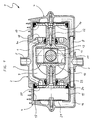
- a compressor 1 has a compressor block 2, a crank loop drive 3 and two cylinder heads 4 on.
- the compressor block 2 has as a feed device for the working medium (namely air) an inlet pipe sleeve 5 and an inlet line system 6, and as a discharge device for the compressed or compressed working medium an outlet pipe sleeve 7 and an outlet pipe system 8; further an inner cavity 9 is provided.
- working medium namely air
- inlet pipe sleeve 5 and an inlet line system 6 and as a discharge device for the compressed or compressed working medium an outlet pipe sleeve 7 and an outlet pipe system 8; further an inner cavity 9 is provided.
- the crank loop drive is in the inner cavity 9 of the compressor block 2 3 housed.
- This has one Crank loop frame 10 on which a backdrop 11 is formed is.
- a sliding block 12 is placed in the backdrop 11 guided.
- the sliding block 12 is eccentrically guided on a crankshaft crank pin 13 and thus transforms e.g. through the crankshaft of an internal combustion engine a rotary motion applied to a truck in a longitudinal movement of the crank loop frame 10 around.
- crank loop frame 10 Piston 14 attached. These lie on one axis and face each other. As a drive, a crank loop is used, the two pistons 14 lead one linear float out.
- each of the cylinder heads 4 there is a working space 15 and an outlet duct 16 are formed.
- a liner 17 In the work room 15 is a liner 17 attached.
- valve lamellae are arranged such that they only one direction of flow into the working space 15 allow.
- the piston 14 then reverses its direction of movement and moves onto the annular feed groove 6a of the inlet pipe system 6 to.
- the valve plate 18 attached there prevents the air from flowing back. This will be pre-compressed and flows through openings 19 in the piston 14 and a valve device arranged behind it 20 in the resulting on the other side of the piston Working space.
- the centers of the openings 19 are on the same radius around the center of the disc-shaped Piston 14 arranged and evenly distributed thereon.
- the extent of the delivery quantity of the compressor 1 is determined by the amount of the in the 1st stage, the pre-compression stage, aspirated working medium determined. Because the working medium that is not so highly compressed at this stage Back expansion share from the dead spaces less. The order receives a much higher degree of delivery.
- the valve plate 21 has such a bias on that they only at a certain, preset Pressure opens.
- the compressed Air is finally expelled into the outlet duct 16 and flows through the discharge line system 8 of the compressor block 2 through the outlet pipe sleeve 7 as compressed air (Compressed air).
- Precompaction is then carried out again during the return stroke Air through openings 19 and valve device 20 of the piston 14 inserted into the work space.
- a second Compressors of the same type connected e.g. a 4-cylinder star arrangement are formed. From two to the Drive shaft connected 4-cylinder compressors can be used 8-cylinder compressors are trained and other possible combinations are always open. An individual Adaptation to the respective performance requirements thus possible without much effort.
- the simple design of the compressor enables also an adaptation to individual circumstances without big design changes.
- Another arrangement e.g. the inlet or outlet device can be easily be performed.
- the crank loop drive 3 also has coated Backdrops 11, the dry running of the backdrop stone 12 enable.
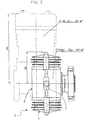
- pistons 30 become immediate through an off-center on a crankshaft that only is indicated indicated, mounted crank pin 33 driven.
- Piston shaft 31 formed sliding surface 32 as a counter surface for the crank pin 33.
- a backdrop and a sliding block are not necessary here.
- the piston skirt 31 is in the area the sliding surface 32 formed such that a spring 34 can clamp the piston 30 against the crank pin 33. This also guarantees the piston return movement.
- the remaining parts, in particular the compression section and the cylinders correspond to those of the first embodiment, so that reference is made to this.
Landscapes
- Engineering & Computer Science (AREA)
- Mechanical Engineering (AREA)
- General Engineering & Computer Science (AREA)
- Chemical & Material Sciences (AREA)
- Combustion & Propulsion (AREA)
- Compressor (AREA)
- Compressors, Vaccum Pumps And Other Relevant Systems (AREA)
Description
Die Erfindung betrifft einen Verdichter bzw. Kompressor zur Verdichtung eines Arbeitsmediums, insbesondere zur Erzeugung von Druckluft, mit zumindest einem in einem Arbeitsraum hin- und herbewegbaren Kolben zum Verdichten des Arbeitsmediums, einer Antriebseinrichtung zur Hin- und Herbewegung des Kolbens sowie mit einer Zuführeinrichtung und einer Abführeinrichtung zur Zufuhr bzw. Abfuhr des Arbeitsmediums, wobei als Antriebseinrichtung ein Kurbelschleifenantrieb vorgesehen ist.The invention relates to a compressor for the compression of a working medium, in particular for production of compressed air, with at least one in a work area reciprocating piston to compress the Working medium, a drive device for reciprocation of the piston and with a feed device and a discharge device for supplying or removing the working medium, a crank loop drive being provided as the drive device.
Als Arbeitmedien werden komprimierbare Stoffe wie Gase oder Dämpfe verwendet, wobei in den herkömmlichen Kompressoren meist Luft verdichtet wird. Diese Druckluft wird z.B. in Lastkraftwagen als Übertragungsmittel in Bremseinrichtungen verwendet.Compressible substances such as gases are used as working media or vapors are used in conventional compressors mostly air is compressed. This compressed air is e.g. in trucks as a means of transmission in braking devices used.
Es sind eine Vielzahl von Tauchkolben-Kompressoren mit Kurbel-Pleuel-Antrieb bekannt. Diese Verdichter arbeiten nach dem Prinzip des Kurbeltriebs und weisen üblicherweise eine Ölschmierung auf. Aufgrund der Schwingbewegung des Pleuels ist es bei diesen Verdichtern schwierig, den arbeitsraum gegenüber dem Kurbelraum abzudichten. Deshalb gelangt Ölleckage an den Kolbenringen vorbei in den Arbeitsraum und führt insbesondere am Auslaßventil zu Ölverkokung. Als Gegenmaßnahme hierzu sind in den herkömmlichen Verdichtern Kühlungseinrichtungen notwendig. Mit diesen wird die Luft- und Bauteiltemperatur reduziert und damit auch das Maß der Ölverkokung herabgesetzt. Die Notwendigkeit einer Kühlung, die meist als Wasser- oder Luftkühlung ausgeführt ist, bedingt aber einen erheblichen konstruktiven Aufwand und einen großen Bauraumbedarf.There are a variety of plunger compressors with Crank-connecting rod drive known. These compressors work on the principle of the crank mechanism and usually have an oil lubrication. Due to the swinging movement of the Connecting rods make it difficult for these compressors to enter the work area to seal against the crankcase. Therefore came Oil leakage past the piston rings into the work area and leads to oil coking, especially at the outlet valve. As a countermeasure to this are in the conventional compressors Cooling devices necessary. With these the Reduced air and component temperature and thus that too Degree of oil coking reduced. The need for one Cooling, which is usually carried out as water or air cooling is, but requires considerable design effort and a large space requirement.
Der konstruktive Aufwand erhöht sich weiter aus der Notwendigkeit, eine Erwärmung der angesaugten Luft durch die abzuführende, komprimierte Luft zu vermeiden. Je wärmer die angesaugte Luft ist, desto geringer wird der Liefergrad der Verdichters aufgrund der mit der Temperaturerhöhung einhergehenden Volumenausdehnung des Arbeitsmediums. Deshalb wird eine größtmögliche bauliche Trennung der Zuführund Abführleitungen für das Arbeitsmedium angestrebt.The design effort increases further from the Need to heat the intake air through to avoid the compressed air to be discharged. The warmer the air sucked in, the lower the delivery rate the compressor due to the increase in temperature accompanying volume expansion of the working medium. Therefore the greatest possible structural separation of the feed and Leakage lines for the working medium are sought.
Ein weiterer Nachteil der herkömmlichen Kompressoren mit diesen einstufigen Verdichtern ist der niedrige Liefergrad. Dieser ist aufgrund des rückexpandlierenden Schadvolumens aus den Toträumen, der hohen Einlaßventilwiderstände wegen der notwendigen Druckstabilität des Ventils und der Aufheizung der Luft durch die ebenfalls im Zylinderkopf geführte heiße Auslaßluft begrenzt.Another disadvantage of conventional compressors with these single-stage compressors is the low delivery rate. This is due to the re-expanding damage volume from the dead spaces, the high intake valve resistances because of the necessary pressure stability of the valve and the Heating of the air through the also in the cylinder head hot exhaust air limited.
Die herkömmlichen Tauchkolben-Kompressoren mit Kurbel-Pleuel-Antrieb bedingen also einen erheblichen konstruktiven Aufwand, eine Vielzahl von Bauteilen und einen großen Bauraumbedarf. Ferner erfordert z.B. eine Lageänderung des Einlaßanschlusses meist eine völlige konstruktive Neugestaltung des Verdichters, da die Leitungsführung der Einlaß- und der Auslaßleitungen sowie der Kühlungsleitungen aufgrund der Wärmeentwicklugen genau aufeinander abgestimmt sein müssen.The conventional plunger compressors with crank-connecting rod drive therefore require a considerable constructive Effort, a variety of components and a large one Space requirements. Furthermore, e.g. a change of location of the Inlet connection usually a complete constructive redesign of the compressor, since the piping of the inlet and the outlet pipes and the cooling pipes precisely matched due to the heat development have to be.
Es ist im Stand er Technik bereits bekannt, Kurbelschleifenantriebe für Brennkraftmaschinen zu verwenden. So zeigt z.B. die DE 32 18 311 C2 einen Kurbelschleifenantrieb, der insbesondere für eine Zweitakt-Brennkraftmaschine vorgesehen ist, die auch ohne Ölschmierung betriebsfähig ist. Weiterhin ist aus der DE 34 47 663 A1 eine Mehrzylinder-Brennkraftkolbenmaschine bekannt, bei der die Umsetzung in eine Drehbewegung mittels eines Kurbelschleifenantrieb erfolgt. Eine weitere Ausführungsform eines solchen Kurbelschleifenantriebs wird in der DE 43 07 205 A1 beschrieben. Bezüglich des genauen Funktionsprinzips und hinsichtlich der Arbeitsweise des Kurbelschleifenantriebs kann daher vollinhaltlich auf die genannten Druckschriften verwiesen werden.It is already known in the state of the art, crank loop drives to use for internal combustion engines. So shows e.g. DE 32 18 311 C2 a crank loop drive, especially for a two-stroke internal combustion engine is provided which is operational even without oil lubrication is. Furthermore, DE 34 47 663 A1 describes a multi-cylinder internal combustion engine known in the implementation in a rotary motion by means of a crank loop drive he follows. Another embodiment of such a crank loop drive is described in DE 43 07 205 A1. Regarding the exact functional principle and regarding the operation of the crank loop drive can therefore full reference to the publications mentioned become.
Der Kurbelschleifenantrieb bietet demmach den Vorteil, daß die Drehbewegung einer Kurbelwelle in eine reine Längsbewegung der Kolben umgewandelt wird. Dies ermöglicht ein sicheres Abdichten der Gleitfläche zwischen dem Kolbenschaft und der Lagerstelle im Verdichterblock. Wenn entsprechend der Lehre der DE-A-2 033 820, der FR-A-364091 oder der BE-A-861533 als Antriebseinrichtung des Verdichters ein Kurbelschleifenantrieb vorgesehen wird, kann sichergestellt werden, daß der Arbeitsraum gegenüber dem Kurbelraum stets ausreichend abgedichtet ist, was den entscheidenden Vorteil hat, daß der Arbeitsraum beidseits des Kolbens für den Verdichtungsvorgang genutzt werden kann und daß keine Ölpartikel in den Arbeitsraun gelangen können.The crank loop drive offers the advantage that that the rotary motion of a crankshaft in a purely longitudinal motion the piston is converted. This enables one secure sealing of the sliding surface between the piston skirt and the bearing in the compressor block. If appropriate the teaching of DE-A-2 033 820, FR-A-364091 or BE-A-861533 a crank loop drive is provided as the drive device of the compressor, can be ensured that the work area opposite the crankcase is always adequately sealed, which has the decisive advantage that the work space used on both sides of the piston for the compression process and that no oil particles get into the work area can.
Dadurch wird eine Verkokung der Ventile, insbesondere des Auslaßventils, vermieden und es kann auf eine Kühlung verzichtet werden. Der erhebliche konstruktive Aufwand zur Gestaltung des Verlaufs der Kühlungskanäle entfällt somit völlig und die Bauform vereinfacht sich wesentlich.This will cause coking of the valves, in particular of the exhaust valve, avoided and it can on cooling to be dispensed with. The considerable design effort The design of the course of the cooling channels is therefore not necessary completely and the design is significantly simplified.
Aufgabe der Erfindung ist es gegenüber der gattungsgemäßen BE-A-861 533 einen Verdichter zu schaffen, bei dem der Arbeitsraum auf einfacher Weise abdichtbar ist. Die Erfindung löst diese Aufgabe durch den Gegenstand des Anspruches 1.Compared to the generic BE-A-861 533, the object of the invention is to create a compressor in which the working space can be sealed in a simple manner. The invention solves this problem by the subject matter of
Der Arbeitsraum kann nach der im Anspruch 2 angegebenen
Weiterbildung der Erfindung auf beiden Seiten des Kolbens
zum einen als Vorverdichtungsraum und zum anderen als
Hauptverdichtungsraum dienen, d.h. die Kolbenbewegung kann
z.B. als Ausstoßbewegung dienen und gleichzeitig zum Ansaugen
von noch unverdichtetem Arbeitsmedium auf der Kolbenrückseite.The workspace can be specified in
Damit ergibt sich ein zweistufiger Verdichter, der das Arbeitsmedium zunächst vorverdichtet und anschließend in einem Hauptverdichtungshub ausstößt. Während beim herkömmlichen einstufigen Verdichter das aufgrund von Bauteiltoleranzen und der Wärmeausdehnung auftretende Totvolumen den Liefergrad wesentlich verschlechtert, ist für den zweistufigen Verdichter die Arbeit des Totvolumens nahezu unbedeutend, da die Rückexpansion des dortigen Arbeitsmediums direkt zur Vorverdichtung genutzt wird.This results in a two-stage compressor that Working medium first compressed and then in emits a main compression stroke. While the conventional single-stage compressor due to component tolerances and the thermal expansion occurring dead volume Degree of delivery deteriorated significantly, is for the two-tier Compressor the work of the dead volume almost insignificant, because the back expansion of the working medium there is direct is used for pre-compression.
Die in das Totvolumen eingebrachte Verdichtungsenergie ist somit nicht verloren und ermöglicht deshalb einen wesentlich höheren Wirkungsgrad bzw. Liefergrad. Mit einer solchen Anordnung läßt sich z.B. der Liefergrad gegenüber 55% bei einem herkömmlichen Serienkompressor auf 80% beim Kurbelschleifenkompressor mit Vorverdichtung anheben.The compression energy introduced into the dead volume is therefore not lost and therefore enables a significant higher efficiency or delivery rate. With a such an arrangement can e.g. the degree of delivery versus 55% with a conventional series compressor to 80% with Raise the crank loop compressor with pre-compression.
Der Liefergrad wird in der erfindungsgemäßen Anordnung durch das Volumen des Vorverdichtungsraumes bestimmt. Das hier auftretende Totvolumen ist aber aufgrund des niedrigeren Drucks von geringerer Bedeutung, da das rückexpandierende Schadvolumen nicht so umfangreich ist. Das Arbeitsmedium im Vorverdichtungsraum wird nahezu völlig in den Hauptverdichtungsraum übergeführt und das dort auftretende Totvolumen setzt die darin eingebrachte Energie wieder zur Unterstützung der Rückbewegung des Kolbens und somit für die Vorverdichtung ein.The degree of delivery is in the arrangement according to the invention determined by the volume of the pre-compression space. The dead volume occurring here is due to the lower Pressure of less importance because the back-expanding Damage volume is not as extensive. The working medium in the precompression room is almost completely in the Main compression space transferred and what occurs there Dead volume restores the energy introduced into it Support for the return movement of the piston and thus for the pre-compression.
Die Ausbildung in einem hintereinander geschalteten Vor- und Hauptverdichtungsraum ermöglicht eine einfache Ventilanordnung. Jeder Verdichtungsraum benötigt daher gemäß der im Anspruch 3 angegebenen Weiterbildung der Erfindung nur jeweils eine Ventileinrichtung für die Zufuhr und eine Ventileinrichtung für die Abfuhr des Arbeitsmediums. Diese Ventileinrichtungen können zudem sehr einfach und betriebssicher gestaltet werden. Der konstruktive Aufwand verringert sich somit wesentlich und die bauliche Ausführungsform vereinfacht sich hierdurch erheblich.Training in a series The pre-compression and main compression space enables easy Valve arrangement. Every compression space therefore needs the development of the invention specified in claim 3 only one valve device for the supply and a valve device for the removal of the working medium. These valve devices can also be very simple and reliable be designed. The construction effort thus significantly reduced and the structural embodiment this simplifies considerably.
Dadurch, daß der Raum beidseitig des Kolbens als Arbeitsraum
Verwendung findet, ergibt sich der Vorteil, daß
eine räumliche Trennung der Zuführeinrichtung von der Abführeinrichtung,
wie z.B. eine Anordnung auf axial gegenüberliegenden
Seiten des Kolbens gemäß der im Anspruch 4
angegebenen Weiterbildung der Erfindung, ermöglicht wird.
Die Zuführeinrichtung kann also z.B. im Verdichterblock angeordnet
werden, während die Abführeinrichtung im Zylinderkopf
vorgesehen ist und die weitere Leitungsführung beliebig
gewählt werden kann. Somit kann die Erwärmung des zugeführten
Arbeitsmediums durch das aufgrund des Druckvorgangs
erwärmte abgeführte Arbeitsmedium vermieden werden. Ein
konstruktives Hauptproblem herkömmlicher Verdichter entfällt
damit und die Bauweise des Verdichters vereinfacht
sich wesentlich.The fact that the space on both sides of the piston as a working space
Is used, there is the advantage that
a spatial separation of the feed device from the discharge device,
such as. an arrangement on axially opposite
Sides of the piston according to that in
Eine auf den Arbeitsraum hin gerichtete ringförmige Zuführnut
gemäß der im Anspruch 5 angegebenen Weiterbildung
der Erfindung ermöglicht ein gleichmäßiges Einströmen des
angesaugten Arbeitsmediums in den Vorverdichtungsraum.An annular feed groove directed towards the work area
according to the training specified in
Wenn der Kolben nach der im Anspruch 6 angegebenen Weiterbildung
der Erfindung als kreisförmige Scheibe ausgebildet
wird, so erlaubt dies eine einfache und kostengünstige
Herstellung desselben. Ferner können die bewegten Massen
und die Größe der Reibungsflächen gering gehalten werden.If the piston according to the training specified in
Da der scheibenförmige Kolben gemäß Anspruch 7 vorzugsweise
mit einer Vielzahl von Öffnungen bzw. Durchgangslöchern
ausgebildet ist, ist es möglich auf Überströmkanäle
im Zylinderkopf zu verzichten. Das Arbeitsmedium kann durch
die Öffnungen im Kolben vom Vorverdichtungsraum direkt in
den Hauptverdichtungsraum übergeleitet werden. Der konstruktive
Aufwand für den Zylinderkopf verringert sich so
wesentlich. Ferner wird durch die Öffnungen eine Gewichtsverminderung
des Kolbens erreicht, womit die Größe der zu
bewegenden Masse geringer wird.Since the disc-shaped piston according to
Eine gleichmäßige Verteilung der Öffnungen auf dem Kolben
gemäß der im Anspruch 8 angegebenen Weiterbildung der
Erfindung ermöglicht eine ausgewogene Druckverteilung auf
dem Kolben. Die Belastung auf die Lagerung wird somit nicht
einseitig und der Verschleiß an den Laufflächen bleibt gering.An even distribution of the openings on the piston
according to the further development of the in
Dadurch, daß der Kolben gemäß Anspruch 9 an seinen Öffnungen
vorzugsweise eine Ventileinrichtung aufweist, kann
ein Überströmen des Arbeitsmediums ermöglicht und dabei
aber gleichzeitig der Vorverdichtungsraum vom Hauptverdichtungsraum
abgetrennt werden. Das Arbeitsmedium kann nur in
den Hauptverdichtungsraum hineinströmen, während die Gegenrichtung
gesperrt wird. Somit wird auf einfache Weise eine
Trennung der Verdichtungsräume erreicht und gleichzeitig
die Möglichkeit des direkten Übertritts des Arbeitsmediums
ohne einen Umweg über Kanäle im Zylinderkopf genutzt. Damit
vereinfacht sich die Bauweise des Verdichters weiter.In that the piston according to
Die Ausbildung der Laufbuchse als Tiefziehteil erlaubt eine kostengünstige und präzise Führung des Kolbens.The formation of the liner as a deep-drawn part allows the piston to be guided cost-effectively and precisely.
Ferner ist es dadurch möglich, die Laufbuchse einstückig mit der Ventilplatte auszubilden. Dadurch vermindert sich der Montageaufwand.It is also possible to use the liner to be formed in one piece with the valve plate. Thereby the assembly effort is reduced.
Von weiterem Vorteil ist es, daß gemäß der im Anspruch
10 angegebenen Weiterbildung der Erfindung durch einen Kurbelschleifenantrieb
ohne großen Aufwand zwei gegenläufige
Kolben angetrieben werden können. Somit ist es möglich mit
einer einfachen Bauweise einen Doppelverdichtungszylinder
zu schaffen und die Leistung wesentlich zu erhöhen.Another advantage is that according to the
Diese Bauweise hat ferner den Vorteil, daß mit nur wenigen weiteren Teilen z.B. eine 2-, 4- oder 8-Zylinder-Version des Verdichters ermöglicht wird. Der Verdichter kann somit an entsprechende Leistungsanforderungen ohne großen Aufwand angepaßt werden.This design also has the advantage that with only a few other parts e.g. a 2-, 4- or 8-cylinder version of the compressor is made possible. The compressor can thus to corresponding performance requirements without major Effort to be adjusted.
Die Ausführung als Mehrzylinderanordnung führt weiterhin zu einem gleichmäßigeren Verlauf des Antriebsmomentes im Verhältnis zu den aufgrund der Baugröße und des konstruktiven Aufwands meist nur einzylindrig ausgeführten herkömmlichen Verdichtern.The execution as a multi-cylinder arrangement continues for a more even course of the drive torque in relation to those due to the size and construction Expenses usually only one-cylinder conventional compressors.
Ferner erlaubt der Kurbelschleifenantrieb eine geringe Kolbengeschwindigkeit, wodurch ein Trockenlauf möglich wird. Weiterhin werden nur geringe Massen bewegt und es entstehen nur geringe Tangentialkraftschwankungen, weshalb sich die Festigkeitsanforderungen an den Aufbau wesentlich mindern.Furthermore, the crank loop drive allows a low one Piston speed, which enables dry running becomes. Furthermore, only small masses are moved and it there are only slight fluctuations in tangential force, which is why the strength requirements for the structure reduce.
Der einfache und nur wenige Bauteile aufweisende Aufbau des erfindungsgemäßen Verdichters erlaubt eine kostengünstige und einfache Herstellung und Montage. Wie der Bauraumvergleich mit herkömmlichen Verdichtern zeigt, kann zudem eine kompakte Bauform mit geringen Abmessungen erreicht werden. Ferner ist eine flexible Umgestaltung, z.B. der Einlaßeinrichtung, nach den Gegebenheiten des Einsatzortes ohne großen konstruktiven Aufwand möglich.The simple structure with only a few components of the compressor according to the invention allows inexpensive and easy manufacture and assembly. Like the installation space comparison with conventional compressors can also achieved a compact design with small dimensions become. Furthermore, a flexible redesign, e.g. of the Inlet device, according to the conditions of the site possible without great design effort.
Die Erfindung wird nachstehend anhand der Beschreibung
von Ausführungsbeispielen unter Bezugnahme auf die Zeichnung
näher erläutert. Es zeigt:
Gemäß Fig.1 weist ein Verdichter 1 einen Verdichterblock
2, einen Kurbelschleifenantrieb 3 und zwei Zylinderköpfe
4 auf.1, a
Der Verdichterblock 2 weist als Zuführeinrichtung für
das Arbeitsmedium (nämlich Luft) eine Einlaßrohrmuffe 5 und
ein Einlaßleitungssystem 6, sowie als Abführeinrichtung für
das komprimierte bzw. verdichtete Arbeitsmedium eine Auslaßrohrmuffe
7 und ein Auslaßleitungssystem 8 auf; ferner
ist ein Innenhohlraum 9 vorgesehen.The
Im Innenhohlraum 9 des Verdichterblocks 2 ist der Kurbelschleifenantrieb
3 untergebracht. Dieser weist einen
Kurbelschleifenrahmen 10 auf, auf dem eine Kulisse 11 ausgebildet
ist. In der Kulisse 11 wird ein Kulissenstein 12
geführt. Der Kulissenstein 12 wird durch einen außermittig
auf einer Kurbelwelle gelagerten Kurbelzapfen 13 geführt
und wandelt so die z.B. durch die Kurbelwelle eines Verbrennungsmotors
eines Lastkraftwagens aufgebrachte Drehbewegung
in eine Längsbewegung des Kurbelschleifenrahmens 10
um.The crank loop drive is in the
Ferner sind am Kurbelschleifenrahmen 10 zwei scheibenförmige
Kolben 14 befestigt. Diese liegen auf einer Achse
und stehen einander gegenüber. Da als Antrieb eine Kurbelschleife
verwendet wird, führen die beiden Kolben 14 eine
lineare Hin- und Herbewegung aus. Furthermore, two disc-shaped are on the
In den Zylinderköpfen 4 ist jeweils ein Arbeitsraum 15
und ein Auslaßkanal 16 ausgebildet. Im Arbeitsraum 15 ist
eine Laufbuchse 17 befestigt.In each of the
In Betrieb wird durch die Kolbenbewegung Luft in den
Arbeitsraum 15 angesaugt. Die Luft strömt über die Einlaßrohrmuffe
5 und das Einlaßleitungssystem 6 über eine ringförmige
Zuführnut 6a durch eine auf dem Verdichterblock 2
angeordnete Ventilplatte 18 in den Arbeitsraum 15. Auf der
Ventilplatte 18 sind Ventillamellen derart angeordnet, daß
sie nur eine Strömungsrichtung in den Arbeitsraum 15 hinein
erlauben.In operation, the piston moves air into the
Der Kolben 14 kehrt dann seine Bewegungsrichtung um und
bewegt sich auf die ringförmige Zuführnut 6a des Einlaßleitungssystems
6 zu. Die dort angebrachte Ventilplatte 18
verhindert ein Zurückströmen der Luft. Diese wird somit
vorverdichtet und strömt durch Öffnungen 19 im Kolben 14
und eine dahinter anliegend angeordnete Ventileinrichtung
20 in den sich nun auf der anderen Seite des Kolbens ergebenden
Arbeitsraum. Die Zentren der Öffnungen 19 sind auf
dem gleichen Radius um das Zentrum des scheibenförmigen
Kolbens 14 angeordnet und gleichmäßig darauf verteilt.The
Das Ausmaß der Liefermenge des Verdichters 1 wird durch
die Menge des in der 1. Stufe, der Vorverdichtungsstufe,
angesaugten Arbeitsmediums bestimmt. Da das Arbeitsmedium
in dieser Stufe nicht so hoch verdichtet wird, ist auch der
Rückexpansionsanteil aus den Toträumen geringer. Die Anordnung
erhält so einen wesentlich höheren Liefergrad.The extent of the delivery quantity of the
Die auf die andere Seite des Kolbens 14 übergeströmte
Luft wird dann durch die neuerliche Umkehrung der Kolbenbewegung
verdichtet und gegen eine integral mit der Laufbuchse
17 ausgebildete Ventilplatte 21 gedrückt. Dies ist
möglich, da auch die Lamellen der Ventileinrichtung 20 auf
den Kolben 14 nur eine Strömungsrichtung in den Hauptverdichtungsraum
hinein zulassen.The flow over to the other side of the
Die Ventilplatte 21 weist eine derartige Vorspannung
auf, daß sie erst bei einem bestimmten, voreinstellbaren
Druck öffnet. Beim Öffnen der Ventilplatte 21 wird die komprimierte
Luft schließlich in den Auslaßkanal 16 ausgestoßen
und strömt über das Auslaßleitungssystem 8 des Verdichterblocks
2 durch die Auslaßrohrmuffe 7 als verdichtet Luft
(Druckluft) ab.The
Da auch die Lamellen der Ventilplatte 21 nur eine Strömungsrichtung
zulassen, wird ein Zurückströmen der komprimierten
Luft in den Arbeitsraum 15 beim Rückhub des Kolbens
14 vermieden.Since the fins of the
Die in den aufgrund der Bauteiltoleranzen und der Wärmeausdehnung
vorliegenden Toträumen komprimierte Luft dehnt
sich beim Rückhub des Kolbens 14 wieder aus und unterstützt
den Rückhub und damit die Vorverdichtung der Luft auf der
anderen Kolbenseite.The in due to the component tolerances and thermal expansion
existing dead spaces compressed air expands
back out and supported during the return stroke of the
Während des Rückhubs wird dann wieder vorverdichtete
Luft durch die Öffnungen 19 und die Ventileinrichtung 20
des Kolbens 14 in den Arbeitsraum eingeführt.Precompaction is then carried out again during the return stroke
Air through
Da der Kolben 14 eine rein lineare Bewegung ausführt,
kann ein Kolbenschaft 22 problemlos im Verdichterblock 2
geführt und mittels einer Dichtungseinrichtung 23 gegenüber
dem Innenholraum 9 des Verdichterblocks 2, der den Kurbelschleifenantrieb
3 beherbergt, abgedichtet werden. Somit
kann vermieden werden, daß Ölpartikel in den Arbeitsraum 15
gelangen und eine Ölverkokung der Ventileinrichtungen verursachen.
Damit werden Einrichtungen zum Kühlen des Verdichters
nicht benötigt und der konstruktive Aufwand verringert
sich bedeutend. Since the
Durch eine weitere Dichtungseinrichtung 24, die umfangsseitig
am Kolben 14 angeordnet ist, werden die Verdichtungsräume
beidseits des Kolbens 14 gegeneinander abgedichtet.Through a
Da diese Anordnung nur eine relativ geringe Kolbengeschwindigkeit erfordert, ist ein Trockenlauf möglich. Auch deshalb ist keine Kühlungseinrichtung notwendig und die Bauweise vereinfacht sich weiter.Because this arrangement only has a relatively low piston speed requires a dry run is possible. Also therefore no cooling device is necessary and Construction is further simplified.
An der Antriebswelle des erfindungsgemäßen Verdichters kann problemlos mit wenigen weiteren Bauteilen ein zweiter Verdichter derselben Bauart angeschlossen und so z.B. eine 4-Zylinder-Sternanordnung gebildet werden. Aus zwei an der Antriebswelle verbundenen 4-Zylinder-Verdichtern kann ein 8-Zylinder-Verdichter ausgebildet werden und weitere Kombinationsmöglichkeiten stehen jederzeit offen. Eine individuelle Anpassung an die jeweiligen Leistungsanforderungen ist somit ohne großen Aufwand möglich.On the drive shaft of the compressor according to the invention can easily with a few other components a second Compressors of the same type connected, e.g. a 4-cylinder star arrangement are formed. From two to the Drive shaft connected 4-cylinder compressors can be used 8-cylinder compressors are trained and other possible combinations are always open. An individual Adaptation to the respective performance requirements thus possible without much effort.
Die einfache Ausgestaltung des Verdichters ermöglicht zudem eine Anpassung an individuelle Gegebenheiten ohne große konstruktive Änderungen. Eine andere Anordnung z.B. der Einlaß- oder Auslaßeinrichtung kann ohne großen Aufwand durchgeführt werden.The simple design of the compressor enables also an adaptation to individual circumstances without big design changes. Another arrangement e.g. the inlet or outlet device can be easily be performed.
Der Kurbelschleifenantrieb 3 weist ferner beschichtete
Kulissen 11 auf, die einen Trockenlauf des Kulissensteins
12 ermöglichen.The crank loop drive 3 also has coated
In Fig. 2 ist eine vereinfachte Ausführungsform eines
Kurbelschleifenantriebs gezeigt; in dieser sind mit den
gleichen Bezugszeichen jeweils die gleichen Teile bezeichnet.
Bei dieser Ausführungsform werden Kolben 30 unmittelbar
durch einen außermittig auf einer Kurbelwelle, die nur
angedeutet dargestellt ist, gelagerten Kurbelzapfen 33 angetrieben.
In dieser Ausführungsform dient eine auf einem
Kolbenschaft 31 ausgebildete Gleitfläche 32 als Gegenfläche
für den Kurbelzapfen 33. Eine Kulisse und ein Kulissenstein
sind hier nicht notwendig. Der Kolbenschaft 31 ist im Bereich
der Gleitfläche 32 derart ausgebildet, daß eine Feder
34 den Kolben 30 gegen den Kurbelzapfen 33 spannen kann.
Damit ist auch die Kolbenrückbewegung gewährleistet. Die
übrigen Teile, insbesondere der Verdichtungsabschnitt und
die Zylinder, entsprechen denen des ersten Ausführungsbeispiels,
so daß hierauf verwiesen wird.2 is a simplified embodiment of a
Crank loop drive shown; are in this with the
same reference numerals denote the same parts.
In this embodiment,
In Fig. 3 ist die kompakte Bauform des erfindungsgemäßen Verdichters im Bauraumvergleich mit einem herkömmlichen Verdichter derselben Leistung gezeigt. Aus diesem Vergleich wird deutlich, daß der erfindungsgemäße Verdichter wesentlich weniger Platz beansprucht.3 is the compact design of the invention Compressor in the installation space comparison with a conventional one Compressors of the same performance shown. From this comparison it is clear that the compressor according to the invention is essential takes up less space.
Bezüglich weiterer, hier nicht näher beschriebener Merkmale, Vorteil und Wirkungen der Erfindung wird ausdrücklich auf die Zeichnung verwiesen.Regarding further, not described here in more detail Features, advantages and effects of the invention are made explicit referred to the drawing.
Claims (11)
- Compressor (1) for compressing a working medium, in particular for producing compressed air, having at least one piston (14) which can be moved backwards and forwards in a working chamber (15) to compress the working medium, a drive device for moving the piston (14) backwards and forwards, and a supply device and a discharge device for the supply and discharge of the working medium, a crank guide drive (3) being provided as the drive device,
characterised in that
the piston (14) travels in a liner which is constructed as a deep-draw part integral with the valve plate (21). - Compressor according to claim 1, characterised in that the working chamber (15) is divided into a pre-compression chamber and a main compression chamber by the piston (14) moving backwards and forwards.
- Compressor according to claim 2, characterised in that the pre-compression chamber and the main compression chamber each have only one valve device for the supply and discharge of the working medium.
- Compressor according to one of claims 1 to 3, characterised in that the supply and discharge device - seen in the direction of movement of the piston (14) - are arranged on opposite sides of the piston (14) of the crank guide drive (3).
- Compressor according to one of claims 1 to 4, characterised in that the supply device is constructed as an inlet line system (6) arranged in a compressor block (2), the inlet line system (6) being provided with an annular supply groove (6a) facing towards the working chamber.
- Compressor according to one of claims 1 to 5, characterised in that the piston (14) is constructed as a circular disc.
- Compressor according to one of claims 1 to 6, characterised in that a plurality of apertures (19) extending in the axial direction are formed in the piston (14).
- Compressor according to claim 7, characterised in that the centres of the apertures (19) are located on the same radius and are uniformly distributed on the piston (14) about the centre of the piston (14).
- Compressor according to claim 7 or 8, characterised in that the piston (14) is provided with a valve device (20) arranged at the apertures (19).
- Compressor according to one of claims 1 to 9, characterised in that the crank guide drive (3) drives a double compression cylinder with two oppositely acting pistons (4).
- Compressor according to one of claims 1 to 10, characterised in that the compressor is constructed in accordance with a modular assembly technique, for instance as a 2, 4 or 8 cylinder version.
Applications Claiming Priority (3)
| Application Number | Priority Date | Filing Date | Title |
|---|---|---|---|
| DE19501220 | 1995-01-17 | ||
| DE19501220A DE19501220A1 (en) | 1995-01-17 | 1995-01-17 | compressor |
| PCT/DE1995/001706 WO1996022464A1 (en) | 1995-01-17 | 1995-12-01 | Compressor |
Publications (2)
| Publication Number | Publication Date |
|---|---|
| EP0804684A1 EP0804684A1 (en) | 1997-11-05 |
| EP0804684B1 true EP0804684B1 (en) | 1999-03-10 |
Family
ID=7751660
Family Applications (1)
| Application Number | Title | Priority Date | Filing Date |
|---|---|---|---|
| EP95939216A Expired - Lifetime EP0804684B1 (en) | 1995-01-17 | 1995-12-01 | Compressor |
Country Status (4)
| Country | Link |
|---|---|
| US (1) | US5879145A (en) |
| EP (1) | EP0804684B1 (en) |
| DE (2) | DE19501220A1 (en) |
| WO (1) | WO1996022464A1 (en) |
Families Citing this family (26)
| Publication number | Priority date | Publication date | Assignee | Title |
|---|---|---|---|---|
| DE19706066A1 (en) * | 1997-02-17 | 1997-11-20 | Hans Dipl Ing Unger | Compressor providing compressed air in vehicle |
| DE19739662A1 (en) * | 1997-09-10 | 1999-03-11 | Bosch Gmbh Robert | Valve system for reciprocating compressor of braking system in commercial vehicle |
| DE19755771A1 (en) * | 1997-12-16 | 1999-06-24 | Ludwig Wagenseil | Hydraulic pump operated by combustion fuel |
| US6663361B2 (en) * | 2000-04-04 | 2003-12-16 | Baker Hughes Incorporated | Subsea chemical injection pump |
| AU2002306130A1 (en) * | 2002-05-31 | 2003-12-19 | Xiufeng Gao | Yoke mechanism for compressor |
| AU2002306129A1 (en) * | 2002-05-31 | 2003-12-19 | Xiufeng Gao | Multi-stage compressor |
| US6832900B2 (en) * | 2003-01-08 | 2004-12-21 | Thomas Industries Inc. | Piston mounting and balancing system |
| KR20050066322A (en) * | 2003-12-26 | 2005-06-30 | 삼성전자주식회사 | Compressor |
| ITVI20040051A1 (en) | 2004-03-12 | 2004-06-12 | Gentilin Srl | ALTERNATIVE VOLUMETRIC COMPRESSOR |
| US7481627B2 (en) * | 2004-08-30 | 2009-01-27 | Mat Industries Llc | Air compressor tools that communicate with an air compressor |
| US20060045751A1 (en) * | 2004-08-30 | 2006-03-02 | Powermate Corporation | Air compressor with variable speed motor |
| US20060045749A1 (en) * | 2004-08-30 | 2006-03-02 | Powermate Corporation | Air compressor utilizing an electronic control system |
| DE102004061233B3 (en) * | 2004-12-20 | 2006-07-13 | Knorr-Bremse Systeme für Nutzfahrzeuge GmbH | Dry running compressor, in particular swash plate compressor, with a piston rod storage |
| US7475627B2 (en) * | 2005-09-27 | 2009-01-13 | Ragain Air Compressors, Inc. | Rotary to reciprocal power transfer device |
| DE102006007743B4 (en) * | 2006-02-20 | 2016-03-17 | Knorr-Bremse Systeme für Nutzfahrzeuge GmbH | Reciprocating compressor with non-contact gap seal |
| US8328538B2 (en) * | 2007-07-11 | 2012-12-11 | Gast Manufacturing, Inc., A Unit Of Idex Corporation | Balanced dual rocking piston pumps |
| CN101963145B (en) * | 2010-11-04 | 2013-04-10 | 浙江鸿友压缩机制造有限公司 | Lubrication device for air compressor |
| US9856866B2 (en) | 2011-01-28 | 2018-01-02 | Wabtec Holding Corp. | Oil-free air compressor for rail vehicles |
| CN102777343B (en) * | 2012-06-20 | 2015-03-04 | 杭州海胜制冷设备有限公司 | Single-drive multi-cylinder compressor structure |
| CN104728080B (en) * | 2015-03-28 | 2016-03-23 | 孙万春 | High thrust opposed type reciprocating pump |
| US20180195503A1 (en) * | 2017-01-11 | 2018-07-12 | Bristol Compressors International, Llc | Fluid compressor |
| PL3699428T3 (en) * | 2017-10-19 | 2022-09-19 | Active Tools International (Hk) Ltd. | Air compressor cylinder, air compressor, vehicle seat, and vehicle |
| CN114109771A (en) * | 2021-10-25 | 2022-03-01 | 浙江鸿音机电科技有限公司 | Reciprocating piston type compressor |
| US11913441B2 (en) * | 2021-12-29 | 2024-02-27 | Transportation Ip Holdings, Llc | Air compressor system having a hollow piston forming an interior space and a check valve in a piston crown allowing air to exit the interior space |
| CN115263723B (en) * | 2022-08-25 | 2024-01-30 | 瑞立集团瑞安汽车零部件有限公司 | Cylinder body, air compressor and commercial vehicle |
| CN116066337A (en) * | 2023-03-29 | 2023-05-05 | 湖南腾智机电有限责任公司 | A high-efficiency double-cylinder diaphragm vacuum pump |
Family Cites Families (10)
| Publication number | Priority date | Publication date | Assignee | Title |
|---|---|---|---|---|
| FR364091A (en) * | 1906-02-03 | 1906-08-14 | Platt Iron Works Company | Air compressors |
| US1266595A (en) * | 1913-03-06 | 1918-05-21 | Gen Chemical Corp | Process of making carbon-dioxid and solid sodium sulfite. |
| US2229545A (en) * | 1939-01-30 | 1941-01-21 | Harry A Beckstrom | Engine |
| GB611057A (en) * | 1945-10-10 | 1948-10-25 | Prec Developments Co Ltd | Improvements relating to valve arrangements for reciprocating hydraulic pumps |
| GB840499A (en) * | 1958-04-22 | 1960-07-06 | Sidney Owen Grimsdick | Dosing device |
| DE2033820C3 (en) * | 1970-07-08 | 1975-05-15 | Patrick Joseph Dublin Walls | Internal combustion engine |
| BE861533A (en) * | 1977-12-06 | 1978-03-31 | Bullaert Daniel E | NEW DRIVE MECHANISMS FOR OIL-FREE COMPRESSORS AND HEAT PUMPS |
| US4242878A (en) * | 1979-01-22 | 1981-01-06 | Split Cycle Energy Systems, Inc. | Isothermal compressor apparatus and method |
| US5252045A (en) * | 1990-05-11 | 1993-10-12 | Toyo Engineering Corporation | Dual piston reciprocating vacuum pump |
| US5769616A (en) * | 1994-04-11 | 1998-06-23 | Mencarelli; Enzo | Submerged pump with coaxial opposing pistons, driven by double lobed camshaft |
-
1995
- 1995-01-17 DE DE19501220A patent/DE19501220A1/en not_active Withdrawn
- 1995-12-01 WO PCT/DE1995/001706 patent/WO1996022464A1/en not_active Ceased
- 1995-12-01 DE DE59505338T patent/DE59505338D1/en not_active Expired - Lifetime
- 1995-12-01 US US08/875,619 patent/US5879145A/en not_active Expired - Lifetime
- 1995-12-01 EP EP95939216A patent/EP0804684B1/en not_active Expired - Lifetime
Also Published As
| Publication number | Publication date |
|---|---|
| DE19501220A1 (en) | 1996-07-18 |
| US5879145A (en) | 1999-03-09 |
| DE59505338D1 (en) | 1999-04-15 |
| EP0804684A1 (en) | 1997-11-05 |
| WO1996022464A1 (en) | 1996-07-25 |
Similar Documents
| Publication | Publication Date | Title |
|---|---|---|
| EP0804684B1 (en) | Compressor | |
| DE3224482C2 (en) | PISTON MACHINE | |
| DE69308527T2 (en) | Multi-stage vacuum pump | |
| DE69104093T2 (en) | Air conditioning compressor. | |
| DE4110647A1 (en) | PISTON COMPRESSOR | |
| DE4326408C2 (en) | Multiple axial piston compressors | |
| EP0093732B1 (en) | Device in a pressure system | |
| EP0500825A1 (en) | Reciprocating pump. | |
| DE19506184A1 (en) | Reciprocating piston engine powered by compressed air or other medium | |
| DE3928006C2 (en) | Axial piston pump for liquids, especially for use with high-pressure cleaning devices | |
| DE2811460A1 (en) | CURVED CYLINDER | |
| DE102022103714A1 (en) | Internal combustion engine with charging system | |
| EP2054594B1 (en) | Internal combustion engine having integrated supercharging | |
| DE19727987C2 (en) | Two-stroke swashplate internal combustion engine | |
| WO1999022118A1 (en) | Device for conveying a medium or propulsion through a medium | |
| DE4405689C2 (en) | Gas routing mechanism in a piston compressor | |
| DE62139C (en) | Pump with two pistons moving in opposite directions in a cylinder | |
| DE4431798C2 (en) | Internal combustion engine for motor vehicles | |
| DE3433261A1 (en) | Rotary piston engine with sliding vanes mounted for rotary oscillation on the outer mating body | |
| DE3300199A1 (en) | Engine compressor | |
| DE4404100C2 (en) | Cooling gas compressor | |
| DE3121804C2 (en) | Internal combustion engine for pulverulent fuels, in particular pulverized coal | |
| DE10147469A1 (en) | refrigeration compressor | |
| DE4339376A1 (en) | Coolant gas piston compressor with rotary suction valve - which co-rotates with drive shaft, has outer peripheral wall, and opposite end sections | |
| DE29711460U1 (en) | Two-stroke swashplate internal combustion engine |
Legal Events
| Date | Code | Title | Description |
|---|---|---|---|
| PUAI | Public reference made under article 153(3) epc to a published international application that has entered the european phase |
Free format text: ORIGINAL CODE: 0009012 |
|
| 17P | Request for examination filed |
Effective date: 19970814 |
|
| AK | Designated contracting states |
Kind code of ref document: A1 Designated state(s): DE FR GB |
|
| GRAG | Despatch of communication of intention to grant |
Free format text: ORIGINAL CODE: EPIDOS AGRA |
|
| GRAG | Despatch of communication of intention to grant |
Free format text: ORIGINAL CODE: EPIDOS AGRA |
|
| GRAH | Despatch of communication of intention to grant a patent |
Free format text: ORIGINAL CODE: EPIDOS IGRA |
|
| 17Q | First examination report despatched |
Effective date: 19980609 |
|
| GRAH | Despatch of communication of intention to grant a patent |
Free format text: ORIGINAL CODE: EPIDOS IGRA |
|
| GRAA | (expected) grant |
Free format text: ORIGINAL CODE: 0009210 |
|
| AK | Designated contracting states |
Kind code of ref document: B1 Designated state(s): DE FR GB |
|
| REF | Corresponds to: |
Ref document number: 59505338 Country of ref document: DE Date of ref document: 19990415 |
|
| ET | Fr: translation filed | ||
| GBT | Gb: translation of ep patent filed (gb section 77(6)(a)/1977) |
Effective date: 19990614 |
|
| PLBE | No opposition filed within time limit |
Free format text: ORIGINAL CODE: 0009261 |
|
| STAA | Information on the status of an ep patent application or granted ep patent |
Free format text: STATUS: NO OPPOSITION FILED WITHIN TIME LIMIT |
|
| 26N | No opposition filed | ||
| REG | Reference to a national code |
Ref country code: GB Ref legal event code: IF02 |
|
| PGFP | Annual fee paid to national office [announced via postgrant information from national office to epo] |
Ref country code: GB Payment date: 20121218 Year of fee payment: 18 |
|
| PGFP | Annual fee paid to national office [announced via postgrant information from national office to epo] |
Ref country code: FR Payment date: 20130123 Year of fee payment: 18 |
|
| GBPC | Gb: european patent ceased through non-payment of renewal fee |
Effective date: 20131201 |
|
| REG | Reference to a national code |
Ref country code: FR Ref legal event code: ST Effective date: 20140829 |
|
| PG25 | Lapsed in a contracting state [announced via postgrant information from national office to epo] |
Ref country code: GB Free format text: LAPSE BECAUSE OF NON-PAYMENT OF DUE FEES Effective date: 20131201 Ref country code: FR Free format text: LAPSE BECAUSE OF NON-PAYMENT OF DUE FEES Effective date: 20131231 |
|
| PGFP | Annual fee paid to national office [announced via postgrant information from national office to epo] |
Ref country code: DE Payment date: 20141218 Year of fee payment: 20 |
|
| REG | Reference to a national code |
Ref country code: DE Ref legal event code: R071 Ref document number: 59505338 Country of ref document: DE |