EP0804670B1 - Bauelement - Google Patents
Bauelement Download PDFInfo
- Publication number
- EP0804670B1 EP0804670B1 EP95936992A EP95936992A EP0804670B1 EP 0804670 B1 EP0804670 B1 EP 0804670B1 EP 95936992 A EP95936992 A EP 95936992A EP 95936992 A EP95936992 A EP 95936992A EP 0804670 B1 EP0804670 B1 EP 0804670B1
- Authority
- EP
- European Patent Office
- Prior art keywords
- front element
- building front
- frames
- displaceable
- frame
- Prior art date
- Legal status (The legal status is an assumption and is not a legal conclusion. Google has not performed a legal analysis and makes no representation as to the accuracy of the status listed.)
- Expired - Lifetime
Links
- 239000000725 suspension Substances 0.000 description 13
- 239000004033 plastic Substances 0.000 description 6
- 229910000831 Steel Inorganic materials 0.000 description 4
- 238000004140 cleaning Methods 0.000 description 4
- 238000010276 construction Methods 0.000 description 4
- 239000011521 glass Substances 0.000 description 4
- 239000000463 material Substances 0.000 description 4
- 238000000034 method Methods 0.000 description 4
- 239000010959 steel Substances 0.000 description 4
- 239000004411 aluminium Substances 0.000 description 3
- XAGFODPZIPBFFR-UHFFFAOYSA-N aluminium Chemical compound [Al] XAGFODPZIPBFFR-UHFFFAOYSA-N 0.000 description 3
- 229910052782 aluminium Inorganic materials 0.000 description 3
- 230000000903 blocking effect Effects 0.000 description 3
- 238000012423 maintenance Methods 0.000 description 3
- XEEYBQQBJWHFJM-UHFFFAOYSA-N Iron Chemical compound [Fe] XEEYBQQBJWHFJM-UHFFFAOYSA-N 0.000 description 2
- 239000002356 single layer Substances 0.000 description 2
- 229910001369 Brass Inorganic materials 0.000 description 1
- 239000004677 Nylon Substances 0.000 description 1
- 230000032683 aging Effects 0.000 description 1
- 239000010951 brass Substances 0.000 description 1
- 239000011248 coating agent Substances 0.000 description 1
- 238000000576 coating method Methods 0.000 description 1
- 238000006073 displacement reaction Methods 0.000 description 1
- 230000000694 effects Effects 0.000 description 1
- 230000008030 elimination Effects 0.000 description 1
- 238000003379 elimination reaction Methods 0.000 description 1
- 229910052742 iron Inorganic materials 0.000 description 1
- 239000002365 multiple layer Substances 0.000 description 1
- 229920001778 nylon Polymers 0.000 description 1
- 238000010422 painting Methods 0.000 description 1
- 238000001556 precipitation Methods 0.000 description 1
- 230000002787 reinforcement Effects 0.000 description 1
- 238000007789 sealing Methods 0.000 description 1
- 230000003068 static effect Effects 0.000 description 1
- 239000002023 wood Substances 0.000 description 1
Images

Classifications
-
- E—FIXED CONSTRUCTIONS
- E06—DOORS, WINDOWS, SHUTTERS, OR ROLLER BLINDS IN GENERAL; LADDERS
- E06B—FIXED OR MOVABLE CLOSURES FOR OPENINGS IN BUILDINGS, VEHICLES, FENCES OR LIKE ENCLOSURES IN GENERAL, e.g. DOORS, WINDOWS, BLINDS, GATES
- E06B3/00—Window sashes, door leaves, or like elements for closing wall or like openings; Layout of fixed or moving closures, e.g. windows in wall or like openings; Features of rigidly-mounted outer frames relating to the mounting of wing frames
- E06B3/32—Arrangements of wings characterised by the manner of movement; Arrangements of movable wings in openings; Features of wings or frames relating solely to the manner of movement of the wing
- E06B3/34—Arrangements of wings characterised by the manner of movement; Arrangements of movable wings in openings; Features of wings or frames relating solely to the manner of movement of the wing with only one kind of movement
- E06B3/42—Sliding wings; Details of frames with respect to guiding
- E06B3/44—Vertically-sliding wings
-
- E—FIXED CONSTRUCTIONS
- E05—LOCKS; KEYS; WINDOW OR DOOR FITTINGS; SAFES
- E05D—HINGES OR SUSPENSION DEVICES FOR DOORS, WINDOWS OR WINGS
- E05D13/00—Accessories for sliding or lifting wings, e.g. pulleys, safety catches
- E05D13/10—Counterbalance devices
- E05D13/14—Counterbalance devices with weights
-
- E—FIXED CONSTRUCTIONS
- E05—LOCKS; KEYS; WINDOW OR DOOR FITTINGS; SAFES
- E05F—DEVICES FOR MOVING WINGS INTO OPEN OR CLOSED POSITION; CHECKS FOR WINGS; WING FITTINGS NOT OTHERWISE PROVIDED FOR, CONCERNED WITH THE FUNCTIONING OF THE WING
- E05F17/00—Special devices for shifting a plurality of wings operated simultaneously
- E05F17/004—Special devices for shifting a plurality of wings operated simultaneously for wings which abut when closed
Definitions
- the present invention relates to a building front element comprising two opposite and parallelly extending guiding profiles adapted to be placed in a generally vertical position, defining lowermost and uppermost ends, two displaceable frames being of substantially the same weight and being received in and guided in respective slideways in the guiding profiles and each having opposite and parallel lateral edges, and a wire system connecting one of the edges of the displaceable frame, being received in and guided in the appertaining slideway in one of the guiding profiles or in the first guiding profile, to the opposite edge of the second displaceable frame which is received in and is guided in the appertaining slideway of the second guiding profile which wire system in addition connects one of the edges of the above mentioned displaceable frame which is received in and guided in the appertaining slideway of the second guiding profile, to the opposite edge of the second displaceable frame which is received in and guided in the appertaining slideway in one of the guiding profiles or in the first guiding profile, and which wire system is guided around the above mentioned uppermost ends of the guiding profiles.
- a building front element of the kind described above is known from Danish utility model registration No. 93 00123 and is characterized by differing from the building front elements disclosed in the above mentioned publications by having window frames which are not especially likely to block by wedging and thus to prevent an effortless and reliable mobility and operation.
- This elimination of blocking by wedging or poor or unreliable function which is often present in the above mentioned older building front elements is obtained by means of two wires constituting a cross suspension which serves the purpose of ensuring that the two displaceable frames of the building front element to the extent possible are always guided in parallel and in balanced state or in an equilibrium.
- An object of the present invention is to provide a building front element of arbitrary size and of the kind described above which compared to the building front element known from the above mentioned Danish utility model registration provides the further advantage that the cross suspension of the building front element may be established in a simple manner without requiring exact adjustment of the two wires of the wire system known from the above mentioned Danish utility model registration in relation to each other and in relation of the two displaceable frames of the building front element and thus in relation to construction and operation improves the building front element known from the above mentioned Danish utility model registration.
- this object is achieved by means of a building front element of the aforementioned kind, which building front element in accordance with the realization upon which the present invention is based is characterized in that the wire system comprises a single wire which is guided around the lowermost edge of the two displaceable frames which is arranged lowermost in the building front element constituting a closed loop.
- the building front element known from the above mentioned Danish utility model registration is improved by making the wire system of the building front element so to speak self-adjusting as the closed loop formed by one of the wires of the wire system provides a self-adjusting adaption of the parts of the wire corresponding to the two cros suspension-forming wires of the building front element known from the above-mentioned Danish utility model registration.
- the construction of the cross-suspended wire system as a closed loop facilitates the handling of the building front element.
- any changes in the length of the wires due to use or aging of the two wires of the building front element known from the above mentioned Danish utility model registration is in itself counterbalanced in the building front element according to the present invention, in which the wire system constitutes a closed loop comprising one single wire simultaneously establishing the self-adjusting cross suspension which in accordance with the construction known from the above mentioned Danish utility model registration provides an effortless and frictionless mobility and at the same time provides the possibility of positioning of the two displaceable frames in arbitrary positions, e.g. a totally open or a totally closed position and an arbitrary intermediate partly open or partly closed position.
- a primary use of the building front element according to the present invention is for confining e.g. verandas, balconies, pavement restaurants and the like, where these objects should be opened or closed easily, however still maintaining breastwork.
- the building front element according to the present invention may, however, alternatively be employed as a window element.
- the displaceable frames preferably constitute window frames receiving glass panes of one or more glass sheets, e.g. hardened single-layer glass panes, two- or three-layered insulating panes.
- the displaceable frames may, alternatively, constitute covering panels, e.g. in connection with pavement restaurants or shops providing an enclosure and cover for display- or facade areas during the closing hours of the restaurant or shop in question.
- the displaceable frames of the building front element according to the present invention may be formed with reinforcements, e.g. a grid or a wire.
- the two displaceable frames may be received in separate or respective slideways of the guiding profiles.
- each of the guiding profiles is formed with a single slideway for guiding respective lateral edges of the two displaceable frames, said two displaceable frames being guided in the same slideway of the two guiding profiles.
- the wire of the wire system of the building front element according to the present invention constitutes the above-mentioned cross suspension and may lead from one edge of the first displaceable frame to the opposite edge of the second displaceable frame via bushings, rollers or, in accordance with the presently preferred embodiment of the building front element according to the present invention, around respective reels, arranged at said uppermost ends of the guiding profiles, the two wires further, and preferably, being fixed to the uppermost edges of the two displaceable frames.
- the building front element according to the present invention may alone be formed by the two opposite and mutually parallel guiding profiles, the two displaceable frames with their associated wires constituting the cross suspension, characteristic of the present invention.
- the building front element further comprises two fixed frames placed between the guiding profiles at their uppermost and lowermost ends, respectively, defining an uppermost and a lowermost fixed frame, respectively.
- These uppermost and lowermost frames may be of identical dimensions, or different dimensions, and may, additionally, be identical to or different from the displaceable frames, which may again be of different sizes, as long as the displaceable frames are of the same weight or, alternatively, are balanced to an essentially identical weight.
- all four frames i.e. the two displaceable frames and the two fixed frames, are of identical dimensions, thus providing a building front element which, with the displaceable frames being in their closed position, closes off the building front element completely, and with the displaceable frames being in their opened position, provides an approximately 50 per cent opening of the area of the building front element.
- the fixed frames may be fixated in the guiding profiles or may be received in respective, separate slideways of the guiding profiles, whereby the fixed frames, e.g. for reasons of cleaning and maintenance, may be released from the normally locked or fixed positions and displaced relative to the normal, fixed positions, guided by the respective slideways of the guiding profiles.
- the slideway receiving the uppermost fixed frame is preferably placed externally relative to the tracks receiving the displaceable frames and the lowermost fixed frame, relative to the intended position of the building front element, while the track receiving the lowermost fixed frame, correspondingly is placed internally.
- the uppermost fixed frame overlapping the uppermost displaceable frame which, e.g. via a drip nose, overlaps the lowermost displaceable frame, which again overlaps the lowermost fixed frame.
- the easy access to the two displaceable frames of the building front element through the fixed frames formed as window elements that can be opened may be further improved if the uppermost fixed frame, as seen relative to the intended positioning of the building front element, can be opened outwardly whereas the lowermost fixe frame correspondingly may be opened inwardly.
- the building front element may comprise top and bottom elements joined to the guiding profiles and thus forming an integral frame, of which the guiding profiles constitute frame elements.
- the resulting building front element constitutes an independent unit, of which the bottom element may, preferably, be formed with a drip nose for eliminating possible dewatering problems.
- the building front element according to the present invention preferably constitutes a building front element of a height matching the given and intended use.
- the building front element may advantageously be of a total height which matches the height between two floors.
- the height of the lowermost fixed frame preferably corresponds to the breastwork of a balcony.
- the building front element according to the present invention may be manufactured from any suitable and, preferably, weatherproof material, such as aluminium, plastic or pressure- or vacuum-impregnated wood.
- the building front element may also be manufactured by combining elements of any of the above-mentioned materials.
- the building front element may additionally comprise elements made of e.g. iron profiles formed with a protecting surface coating, e.g. of plastic.
- the wires which according to the present invention constitute the cross suspension, characteristic of the present invention may be produced from any suitable material, such as steel or plastic or any combination thereof, e.g. steel wire covered with plastic of a thickness of e.g. 4 to 8 mm.
- the total width of the building front element is 1 to 2 metres, the building front element comprising four frames, two stationary and two displaceable frames of the same width as the building front element, and each having a height of approximately 0.5 to 1 metre.
- the reels or tackles guiding the cross-suspending steel wires may be manufactured from, say nylon or any durable and preferably non-corroding and weatherproof material, such as plastic, surface-treated or plastic-coated steel, brass or the like.
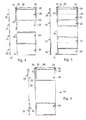
- FIG. 1 shows schematically and perspectively a building front element according to the present invention.
- the building front element as a whole, is designated 10 and comprises two opposite and parallelly extending, lateral elements 12 and 14 which together with opposite top and bottom elements 16 and 18, respectively, form a frame which receives two stationary frames 20 and 26 together with two displaceable frames 22 and 24 which in the positioning of the building front element according to Fig. 1, wherein the building front element is mounted in a generally vertical position, form vertically displaceable frames.
- the fixed frame 20 comprises a circumferential outer, marginal frame 21 and forms an uppermost fixed or stationary frame, while the other fixed frame 26 in the same manner has a circumferential, outer frame 27 and forms a lowermost fixed or stationary frame.
- the displaceable frames 22 and 24 each comprises respective circumferential outer, marginal frames, 23 and 25, respectively. Reels or tackles for wires 34 and 35 are mounted at the upper ends of the lateral elements 12 and 14, the use of which will be apparent from the following description.
- Fig. 2 shows a vertical section through the building front element of Fig. 1 and showing in detail the fixed frames 20 and 26, the displaceable frames 22 and 24 together with top and bottom elements 16 and 18.
- Fig. 2 shows that the marginal edges of each of the displaceable and stationary frames are made up from segments of profiled strips carrying suitable sealing strips and serving to receive and fix respective window panes, formed by hardened single-layer glass windows or multiple-layer insulating windows.
- the top and bottom elements 16 and 18 each carries, as seen in Fig. 2, one slideway; it should be noticed that the lateral elements 12 and 14 shown in Fig. 1, correspondingly comprise one slideway.
- the top element 16 accordingly, is provided with two downwardly extending flanges 16a and 16b, therebetween bordering said slideway and constituting an inwardly and an outwardly protruding flange, respectively, as seen relative to the intended positioning of the building front element.
- the uppoermost fixed frame 20 is received, while the slideway serves the purpose of receiving the two vertically displaceable frames 22 and 24.
- the lowermost fixed frame 26 is received.
- the fixed frames 20 and 26 constitute outwardly and inwardly, respectively, openable window elements and are fixed at the bottom and top elements 16 and 18 by means of profile elements 17 and 19, respectively.
- the construction of the frames 20 and 26 as openable window elements enables, by means of opening of the stationary frames 20 and 26, access from the inner side to the outer side of windows of the displaceable frames 22 and 24 for cleaning of the windows.
- the lowermost displaceable frame 24 is, as apparent from Fig. 2, on the inside provided with a handle 28, preferably formed by a protruding profiled part of the profiled element, forming the uppermost frame part of the frame 25.
- Fig. 2 also shows a wire 36 attached at 40 to the upper edge of the uppermost displaceable frame 22.
- the wire 36 passes around reels 33 and 35 received in a bracket 30 in a closed loop.
- Fig. 3 illustrates the manner in which the reels 33 and 35 are placed at the uppermost end of the lateral element 12, while reels 32 and 34 are arranged at the corresponding uppermost end of the lateral element 14, and received in a corresponding bracket 30.
- Fig. 3 furthermore illustrates the manner in which the wire 36 passes at the uppermost end of the building front element 10 in a crosslike way. This cross-suspension of the vertically displaceable frames 22 and 24 also appears from Figs. 4, 5 and 6; Fig.
- This cross suspension in a closed loop of the displaceable frames 22 and 24 allows for an almost ideal guiding of the vertically displaceable frames which are, at any time, guided mutually parallel and in equilibrium, any tendency of one of the displaceable frames to tip over relative to an intended guiding in the lateral elements 12 and 14 automatically being compensated by this cross suspension, and moreover the closed loop provides a self adjustment of the wire 36 in both sides in relation to the displaceable frames 22 and 24 which accordingly provides a self-realigning effect. Consequently, the cross suspension does not only provide a static balancing of the two displaceable frames 22 and 24, having the same external dimensions and weight, but also a dynamic balancing providing an easy, frictionless displacement.
- the cross-suspension also allows for a positioning of the displaceable frames at any position, either fully closed as shown in Fig. 4, partially opened as shown in Fig. 6, or in any intermediate position, fx a semi-open position as shown in Fig. 5.
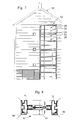
- Fig. 7 shows the application of the building front element described above with reference to Figs. 1-6, in the gable 52 of a house 50.
- the gable 52 forms an external annex, such as a balcony extension or an external, enclosed staircase.
- a total of three complete building front elements are shown together with the upper part of a lowermost building front element, corresponding to a third, a second, and a first storey and the ground floor of the building 50.
- Fig. 7, 54 designates a handrail or balustrade placed on the upper edge of the lowermost fixed frame 26.
- Fig. 8 shows a vertical section through the building front element 10 described above with reference to Figs. 1-6, further showing the mounting of the building front element between two adjacent building components 60 and 62.
- Fig. 8 also shows how the upper fixed frame 20 is intended to be placed outermost, while the lower fixed frame 26 is intended to be placed innermost, thus providing a particularly simple dewatering of the building front element.
- the wires 36 may be mounted freely accessible and visible, or as it is the case in the presently preferred embodiment of the building front element according to the present invention and as illustrated with reference to Figs. 1-8, it my be fixed concealed in the profiles constituting the side elements 12 and 14 in which the displaceable frames are guided.
- the guiding of the wire at the uppermost end of the building front element is concealed to the viewer or user.
- the reels described above may alternatively be provided by means of rollers or wheels that may be mounted on ball or roller bearings, and similarly at the lowermost corners of the lowermost displaceable frame 24, pulleys or rollers may be provided around which the wire 36 is guided in the closed loop as described above.
- the building front element which is in the above and with reference to Figs. 1-8 described embodiment preferably made from extruded, hard anodized aluminium profiles may alternatively be made from pressure- or vacuum-impregnated wooden fillets, if necessary combined with profiled guiding means manufactured from e.g. extruded and hard anodized aluminium.
- the building front element may, as anyone skilled in the art will realize, be formed in any width and height determined by the given application of the building front element.
- the building front element has specific advantages in relation to a virtually 50% openability, easy and unhindered operation and function, allowing for cleaning and maintenance from the inside due to the displaceability of the normally fixed frames 20 and 26.
- the building front element according to the invention is distinguished by not employing a bottom profile section, for example a bottom slide profile, as is normal in connection with conventional, horizontally displaceable frames of verandas or elements for covering balconies, said bottom slide profile often collecting large amounts of dirt and precipitation.
Landscapes
- Engineering & Computer Science (AREA)
- Civil Engineering (AREA)
- Structural Engineering (AREA)
- Mechanical Engineering (AREA)
- Wing Frames And Configurations (AREA)
Claims (12)
- Fassadenelement mit zwei gegenüberliegenden und gegenseitig parallelen Führungsprofilen (12, 14), die zu hauptsächlich vertikaler Positionierung eingerichtet sind, untere und obere Enden definierend, mit zwei beweglichen Rahmen (22, 24), die in der Hauptsache das gleiche Gewicht haben und in jeweiligen Führungsspuren der Führungsprofile aufgenommen und geführt werden, und die jeweils gegenüberliegende, parallele Seitenkanten haben, sowie mit einem Drahtsystem (36), das die Kante des einen beweglichen Rahmens (22, 24), die in der jeweiligen Führungsspur des einen oder ersten Führungsprofils (12, 14) aufgenommen und geführt wird, mit der gegenüberliegenden Kante des anderen beweglichen Rahmens (24, 22), die in der jeweiligen Führungsspur des anderen Führungsprofils (14, 12) aufgenommen und geführt wird, verbindet, welches Drahtsystem ausserdem die Kante des genannten einen beweglichen Rahmens (22, 24), die in der jeweiligen Führungsspur des anderen Führungsprofils (14, 12) aufgenommen und geführt wird, mit der gegenüberliegenden Kante des anderen beweglichen Rahmens (24, 22), die in der jeweiligen Führungsspur des einen oder ersten Führungsprofils (12, 14) aufgenommen und geführt wird, verbindet, und welches Drahtsystem um die oberen Enden der Führungsprofile geführt ist, dadurch gekennzeichnet, dass das Drahtsystem einen einzelnen Draht (36) umfasst, der um die untere Kante desjenigen (24) der beiden beweglichen Rahmen (22, 24) geführt ist, der unten im Fassadenelement angeordnet ist, und eine geschlossene Schleife bildet.
- Fassadenelement nach Anspruch 1, dadurch gekennzeichnet, dass die beweglichen Rahmen (22, 24) Fensterrahmen darstellen, in denen Fensterglas, das aus einem oder mehreren Scheiben besteht, aufgenommen ist.
- Fassadenelement nach Anspruch 1 oder 2, dadurch gekennzeichnet, dass jedes der Führungsprofile eine einzelne Führungsspur zur Führung der jeweiligen Seitenkanten der beiden beweglichen Rahmen (22, 24) hat.
- Fassadenelement nach einem der Ansprüche 1 bis 3, dadurch gekennzeichnet, dass der Draht (36) an den oberen Enden der Führungsprofile um Rollen (30, 32, 33, 35) geführt ist, und dass der Draht an der oberen Kante desjenigen (22) der beiden beweglichen Rahmen (22, 24) befestigt ist, der oben im Fassadenelement angeordnet ist.
- Fassadenelement nach einem der Ansprüche 1 bis 4, dadurch gekennzeichnet, dass das Fassadenelement ausserdem zwei festen Rahmen (20, 26) hat, die zwischen den Führungsprofilen (12, 14) an den oberen bzw. unteren Enden angeordnet sind, einen oberen bzw. einen unteren festen Rahmen definierend.
- Fassadenelement nach Anspruch 5, dadurch gekennzeichnet, dass die festen Rahmen (20, 26) Fensterelemente darstellen, die geöffnet werden können.
- Fassadenelement nach Anspruch 6, dadurch gekennzeichnet, dass der obere feste Rahmen (20), gegenüber der beabsichtigten Positionierung des Fassadenelements gesehen, ausserhalb der Spuren angeordnet ist, in denen die beweglichen Rahmen (22, 24) aufgenommen sind, und das der untere feste Rahmen (26) dementsprechend innerhalb der genannten Spuren angeordnet ist.
- Fassadenelement nach Anspruch 7, dadurch gekennzeichnet, dass der obere feste Rahmen (20), gegenüber der beabsichtigten Positionierung des Fassadenelements gesehen, nach aussen geöffnet werden kann, und dass der untere feste Rahmen (26) dementsprechend nach innen geöffnet werden kann.
- Fassadenelement nach einem der vorhergehenden Ansprüche, dadurch gekennzeichnet, dass das Fassadenelement (10) ausserdem Ober- und Unterteile (16, 18) hat, die mit den Führungsprofilen (12, 14) verbunden sind und einen Gesamtrahmen bilden, wobei die Führungsprofile Rahmenteile darstellen.
- Fassadenelement nach einem der vorhergehenden Ansprüche, dadurch gekennzeichnet, dass das Fassadenelement (10) eine einer Geschosshöhe entsprechende Gesamthöhe hat.
- Fassadenelement nach einem der Ansprüche 5 bis 10, dadurch gekennzeichnet, dass der genannte untere feste Rahmen (26) eine der Brüstungshöhe eines Balkons entsprechende Höhe hat.
- Fassadenelement nach einem der Ansprüche 5 bis 11, dadurch gekennzeichnet, dass die beweglichen Rahmen (22, 24) und die festen Rahmen (20, 26) annährend die gleiche Höhe haben.
Applications Claiming Priority (4)
| Application Number | Priority Date | Filing Date | Title |
|---|---|---|---|
| DK9400435U | 1994-11-18 | ||
| DK9400435U DK9400435U4 (da) | 1994-11-18 | 1994-11-18 | Skydevindue til altaner |
| DK435/94 | 1994-11-18 | ||
| PCT/DK1995/000457 WO1996016244A1 (en) | 1994-11-18 | 1995-11-20 | Building element |
Publications (2)
| Publication Number | Publication Date |
|---|---|
| EP0804670A1 EP0804670A1 (de) | 1997-11-05 |
| EP0804670B1 true EP0804670B1 (de) | 2000-07-05 |
Family
ID=8154953
Family Applications (1)
| Application Number | Title | Priority Date | Filing Date |
|---|---|---|---|
| EP95936992A Expired - Lifetime EP0804670B1 (de) | 1994-11-18 | 1995-11-20 | Bauelement |
Country Status (4)
| Country | Link |
|---|---|
| EP (1) | EP0804670B1 (de) |
| DE (1) | DE69517825D1 (de) |
| DK (1) | DK9400435U4 (de) |
| WO (1) | WO1996016244A1 (de) |
Families Citing this family (3)
| Publication number | Priority date | Publication date | Assignee | Title |
|---|---|---|---|---|
| AU743058B3 (en) * | 1998-07-13 | 2002-01-17 | Aneeta Window Systems (Vic) Pty Ltd | Multi-pane sashless windows |
| AT13674U1 (de) * | 2013-05-28 | 2014-06-15 | Gerfried Dipl Ing Cebrat | Verschiebbare Vordachelemente zur Verschattung und Stromerzeugung |
| CN107401358A (zh) * | 2017-07-03 | 2017-11-28 | 东营坤宝化工有限责任公司 | 一种自动阻音窗及操作方法 |
Family Cites Families (5)
| Publication number | Priority date | Publication date | Assignee | Title |
|---|---|---|---|---|
| US605215A (en) * | 1898-06-07 | Ritory | ||
| US981286A (en) * | 1910-04-06 | 1911-01-10 | Stephen A Lanning | Window-operating device. |
| US1602997A (en) * | 1925-07-16 | 1926-10-12 | Joseph H Beckwith | Sliding door |
| US2654918A (en) * | 1949-03-26 | 1953-10-13 | Anthony G Lemos | Window |
| DK9300123Y6 (da) * | 1993-02-23 | 1993-04-13 | Byens Tegnestue Aps | Facadeelement |
-
1994
- 1994-11-18 DK DK9400435U patent/DK9400435U4/da active Search and Examination
-
1995
- 1995-11-20 DE DE69517825T patent/DE69517825D1/de not_active Expired - Lifetime
- 1995-11-20 EP EP95936992A patent/EP0804670B1/de not_active Expired - Lifetime
- 1995-11-20 WO PCT/DK1995/000457 patent/WO1996016244A1/en not_active Ceased
Also Published As
| Publication number | Publication date |
|---|---|
| DE69517825D1 (de) | 2000-08-10 |
| EP0804670A1 (de) | 1997-11-05 |
| DK9400435U4 (da) | 1996-02-18 |
| WO1996016244A1 (en) | 1996-05-30 |
Similar Documents
| Publication | Publication Date | Title |
|---|---|---|
| US8375516B2 (en) | Joinery | |
| US4115953A (en) | Self sealing heat insulating shutter system | |
| CN1296543A (zh) | 带主框架和窗格覆盖元件的可开启的窗 | |
| CA1328578C (en) | Swinging screen door for sliding glass doors | |
| EP0804670B1 (de) | Bauelement | |
| US4057937A (en) | Window sash assembly | |
| WO1994019572A1 (en) | Building element | |
| US20110079762A1 (en) | Barrier assembly for balconies | |
| FI84645C (fi) | Svaengbar glasbelaeggning. | |
| EP0481911B1 (de) | Rahmenkonstruktion für nach innen öffnende Fenster oder Glastüren | |
| KR20190123424A (ko) | 시스템 이중 창호 | |
| US20030213564A1 (en) | Roller screen housing for a folding window | |
| EP0990762B1 (de) | Fensterladen mit schwenkbaren Lamellen und äusserer Abdeckung | |
| CN219864689U (zh) | 组合式铝合金窗户 | |
| JPS6116369Y2 (de) | ||
| JPH0693771A (ja) | サッシの下部枠 | |
| WO2004027196A1 (en) | Window or door structure with concealed fittings | |
| BE1029760B1 (nl) | Hulpstuk voor een balkondeur en balkondeur uitgerust met dergelijk hulpstuk. | |
| JPS6017494Y2 (ja) | 網戸付き玄関サツシ | |
| JPS5830954Y2 (ja) | サツシの下枠気密装置 | |
| AU609440B2 (en) | Roller shutter which can be fitted to the inside of window openings | |
| IT201800003481A1 (it) | Serramento | |
| GB2312231A (en) | Sliding door assembly | |
| GB2045844A (en) | Cladding for reversible sky-light | |
| JP3420757B2 (ja) | 屋外用下枠フラットサッシの掃除装置 |
Legal Events
| Date | Code | Title | Description |
|---|---|---|---|
| PUAI | Public reference made under article 153(3) epc to a published international application that has entered the european phase |
Free format text: ORIGINAL CODE: 0009012 |
|
| 17P | Request for examination filed |
Effective date: 19970617 |
|
| AK | Designated contracting states |
Kind code of ref document: A1 Designated state(s): BE DE DK ES FR GB IE IT NL SE |
|
| RIN1 | Information on inventor provided before grant (corrected) |
Inventor name: HARILD, JENS Inventor name: HERSKIND, NIELS |
|
| GRAG | Despatch of communication of intention to grant |
Free format text: ORIGINAL CODE: EPIDOS AGRA |
|
| 17Q | First examination report despatched |
Effective date: 19990927 |
|
| GRAG | Despatch of communication of intention to grant |
Free format text: ORIGINAL CODE: EPIDOS AGRA |
|
| GRAH | Despatch of communication of intention to grant a patent |
Free format text: ORIGINAL CODE: EPIDOS IGRA |
|
| GRAH | Despatch of communication of intention to grant a patent |
Free format text: ORIGINAL CODE: EPIDOS IGRA |
|
| GRAA | (expected) grant |
Free format text: ORIGINAL CODE: 0009210 |
|
| AK | Designated contracting states |
Kind code of ref document: B1 Designated state(s): BE DE DK ES FR GB IE IT NL SE |
|
| PG25 | Lapsed in a contracting state [announced via postgrant information from national office to epo] |
Ref country code: NL Free format text: LAPSE BECAUSE OF FAILURE TO SUBMIT A TRANSLATION OF THE DESCRIPTION OR TO PAY THE FEE WITHIN THE PRESCRIBED TIME-LIMIT Effective date: 20000705 Ref country code: IT Free format text: LAPSE BECAUSE OF FAILURE TO SUBMIT A TRANSLATION OF THE DESCRIPTION OR TO PAY THE FEE WITHIN THE PRE;WARNING: LAPSES OF ITALIAN PATENTS WITH EFFECTIVE DATE BEFORE 2007 MAY HAVE OCCURRED AT ANY TIME BEFORE 2007. THE CORRECT EFFECTIVE DATE MAY BE DIFFERENT FROM THE ONE RECORDED.SCRIBED TIME-LIMIT Effective date: 20000705 Ref country code: FR Free format text: LAPSE BECAUSE OF FAILURE TO SUBMIT A TRANSLATION OF THE DESCRIPTION OR TO PAY THE FEE WITHIN THE PRESCRIBED TIME-LIMIT Effective date: 20000705 Ref country code: ES Free format text: THE PATENT HAS BEEN ANNULLED BY A DECISION OF A NATIONAL AUTHORITY Effective date: 20000705 Ref country code: BE Free format text: LAPSE BECAUSE OF FAILURE TO SUBMIT A TRANSLATION OF THE DESCRIPTION OR TO PAY THE FEE WITHIN THE PRESCRIBED TIME-LIMIT Effective date: 20000705 |
|
| REG | Reference to a national code |
Ref country code: IE Ref legal event code: FG4D |
|
| REF | Corresponds to: |
Ref document number: 69517825 Country of ref document: DE Date of ref document: 20000810 |
|
| PG25 | Lapsed in a contracting state [announced via postgrant information from national office to epo] |
Ref country code: DE Free format text: LAPSE BECAUSE OF FAILURE TO SUBMIT A TRANSLATION OF THE DESCRIPTION OR TO PAY THE FEE WITHIN THE PRESCRIBED TIME-LIMIT Effective date: 20001006 |
|
| REG | Reference to a national code |
Ref country code: DK Ref legal event code: T3 |
|
| PG25 | Lapsed in a contracting state [announced via postgrant information from national office to epo] |
Ref country code: IE Free format text: LAPSE BECAUSE OF NON-PAYMENT OF DUE FEES Effective date: 20001120 Ref country code: GB Free format text: LAPSE BECAUSE OF NON-PAYMENT OF DUE FEES Effective date: 20001120 Ref country code: DK Free format text: LAPSE BECAUSE OF NON-PAYMENT OF DUE FEES Effective date: 20001120 |
|
| EN | Fr: translation not filed | ||
| NLV1 | Nl: lapsed or annulled due to failure to fulfill the requirements of art. 29p and 29m of the patents act | ||
| PLBE | No opposition filed within time limit |
Free format text: ORIGINAL CODE: 0009261 |
|
| STAA | Information on the status of an ep patent application or granted ep patent |
Free format text: STATUS: NO OPPOSITION FILED WITHIN TIME LIMIT |
|
| 26N | No opposition filed | ||
| GBPC | Gb: european patent ceased through non-payment of renewal fee |
Effective date: 20001120 |
|
| REG | Reference to a national code |
Ref country code: DK Ref legal event code: EBP |
|
| REG | Reference to a national code |
Ref country code: IE Ref legal event code: MM4A |
|
| PGFP | Annual fee paid to national office [announced via postgrant information from national office to epo] |
Ref country code: SE Payment date: 20011126 Year of fee payment: 7 |
|
| PGFP | Annual fee paid to national office [announced via postgrant information from national office to epo] |
Ref country code: DK Payment date: 20011129 Year of fee payment: 7 |
|
| REG | Reference to a national code |
Ref country code: DK Ref legal event code: EGE |
|
| PG25 | Lapsed in a contracting state [announced via postgrant information from national office to epo] |
Ref country code: SE Free format text: LAPSE BECAUSE OF NON-PAYMENT OF DUE FEES Effective date: 20021121 |
|
| EUG | Se: european patent has lapsed | ||
| REG | Reference to a national code |
Ref country code: DK Ref legal event code: EBP |