EP0804034B1 - Verfahren und Vorrichtung zur Detektion von Bewegungsvektoren - Google Patents
Verfahren und Vorrichtung zur Detektion von Bewegungsvektoren Download PDFInfo
- Publication number
- EP0804034B1 EP0804034B1 EP19960306812 EP96306812A EP0804034B1 EP 0804034 B1 EP0804034 B1 EP 0804034B1 EP 19960306812 EP19960306812 EP 19960306812 EP 96306812 A EP96306812 A EP 96306812A EP 0804034 B1 EP0804034 B1 EP 0804034B1
- Authority
- EP
- European Patent Office
- Prior art keywords
- frame
- distance
- frame distance
- motion
- motion vectors
- Prior art date
- Legal status (The legal status is an assumption and is not a legal conclusion. Google has not performed a legal analysis and makes no representation as to the accuracy of the status listed.)
- Expired - Lifetime
Links
Images


Classifications
-
- H—ELECTRICITY
- H04—ELECTRIC COMMUNICATION TECHNIQUE
- H04N—PICTORIAL COMMUNICATION, e.g. TELEVISION
- H04N19/00—Methods or arrangements for coding, decoding, compressing or decompressing digital video signals
- H04N19/50—Methods or arrangements for coding, decoding, compressing or decompressing digital video signals using predictive coding
- H04N19/503—Methods or arrangements for coding, decoding, compressing or decompressing digital video signals using predictive coding involving temporal prediction
- H04N19/51—Motion estimation or motion compensation
- H04N19/577—Motion compensation with bidirectional frame interpolation, i.e. using B-pictures
-
- H—ELECTRICITY
- H04—ELECTRIC COMMUNICATION TECHNIQUE
- H04N—PICTORIAL COMMUNICATION, e.g. TELEVISION
- H04N19/00—Methods or arrangements for coding, decoding, compressing or decompressing digital video signals
- H04N19/50—Methods or arrangements for coding, decoding, compressing or decompressing digital video signals using predictive coding
- H04N19/503—Methods or arrangements for coding, decoding, compressing or decompressing digital video signals using predictive coding involving temporal prediction
- H04N19/51—Motion estimation or motion compensation
- H04N19/58—Motion compensation with long-term prediction, i.e. the reference frame for a current frame not being the temporally closest one
Definitions
- the present invention generally relates to motion-vector search methods, and particularly relates to a motion-vector search method used for inter-frame predictive coding of image information.
- Image-information-compression coding schemes include internationally-standardized H.261 and H.262, MPEG1 (moving picture experts group 1), and MPEG2 (moving picture experts group 2) among others. These compression coding schemes employ various compression processes such as DCT (discrete cosine transform), motion-compensation inter-frame prediction, etc. Effective enhancement of these compression processes is expected to bring about an improvement in overall compression rates of these schemes.
- DCT discrete cosine transform
- motion-compensation inter-frame prediction etc. Effective enhancement of these compression processes is expected to bring about an improvement in overall compression rates of these schemes.
- Image-information-compression coding schemes include inter-frame predictive coding which draws on redundancy in a time dimension to achieve compression.
- MPEG1 and MPEG2 can handle both a forward prediction and a backward prediction.
- the forward prediction detects changes between a previous frame and a current frame, and generates the current frame based on the previous frame.
- Fig.1A is an illustrative drawing for explaining the forward prediction.
- Fig.1A picture movement between a current frame, which is to be forwardly predicted, and a reference frame (previous frame) is detected within a predetermined range defined for motion-vector search. Then, parts of the picture showing no movement are provided with zero motion vectors, and parts of the picture showing some movement are provided with corresponding motion vectors. These motion vectors are used for coding.
- Fig.1B is an illustrative drawing for explaining the motion-vector search.
- a given frame is divided into a plurality of blocks B 1 , B 2 , ⁇ . Each of these blocks is separately subjected to subsequent DCT and quantization processes.
- a motion-vector-search process a given block B N of a forwardly-predicted frame is searched for in the reference frame within the motion-vector-search range. Namely, a block B' N having the highest correlation with the block B N is detected within the motion-vector-search range of the reference frame.
- movement of the block B N is then represented by a motion vector M N .
- a differential between the block B N and the block B' N is obtained by aligning these two blocks, and is subjected to the DCT and quantization processes. Results thus obtained and the motion vector M N are transmitted, stored, etc., as a part of coded pictures. The same processes are applied to all the blocks shown in Fig.1B
- a bidirectional prediction generates the current frame based on a previous frame (past frame) and a subsequent frame (future frame).
- Fig.2 is an illustrative drawing for explaining the bidirectional prediction.
- the current frame is coded by using a backward motion vector and a forward motion vector which are obtained based on a backward reference frame and a forward reference frame.
- the directional prediction has a higher prediction efficiency than does the forward prediction. Since the directional prediction suffers from twice the processing load, however, it is a general practice to reduce the size of the motion-vector-search range by half for the directional prediction.
- Pictures coded based on the forward prediction are called P-pictures (predictive pictures), and pictures coded based on the directional prediction are called B-pictures (bidirectionally predictive pictures).
- pictures coded by intra-frame coding are called I-pictures (intra pictures).
- MPEG1 and MPEG2 employ a coding scheme which combines the intra-frame coding, the forwardly-predictive coding, and the directionally-predictive coding together, so that a picture sequence can be represented as IBBPBBPBB ⁇ IBBPBBPBBP ⁇ , for example.
- inter-frame predictive coding In the inter-frame predictive coding of the related art, a fixed inter-frame distance is used for motion-vector search. (The inter-frame distance refers to a time distance between frames.) When an inter-frame distance is short for the forward prediction and the motion-vector-search range is relatively large, for example, some motion-vector-search process is likely to be wasted by searching in excess of a maximum range of actually existing picture motions. Also, the inter-frame predictive coding of the related art uses a fixed number of bidirectionally-predictive-coded frames. An increase in the number of these frames may result in a situation where the motion-vector-search range for the forward prediction is not sufficiently large. In this case, the prediction efficiency is decreased.
- a method of detecting motion vectors within a predetermined search range for motion-compensation predictive coding includes the steps of searching for first motion vectors between two frames which are separated from each other in a time dimension by a first frame distance, selecting a second frame distance of two frames between which picture motion is represented by second motion vectors, making a check whether the predetermined search range covers a predetermined percentage of the second motion vectors, the check using the first motion vectors as estimates of the second motion vectors after compensation for a difference between the first frame distance and the second frame distance, and deciding, based on results of the check, whether to increase a frame distance for prediction.
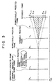
- Fig.3 is an illustrative drawing for explaining the principle of the present invention.
- frames O and F 1 -F 6 are temporary successive frames.
- the frame F 1 is a frame to be bidirectionally predicted based on the frames O and F 2 .
- the frame F 4 is then the frame to be forwardly predicted using the frame F 2 as a reference frame.
- the frame F 3 is bidirectionally predicted using the frames F 2 and F 4 as reference frames.
- the frame F 6 will be a frame to be forwardly predicted using the frame F 4 as a reference frame
- the frame F 5 will be bidirectionally predicted based on the frames F 4 and F 6 .
- x u3 and x l3 are boundaries to define a motion-vector-search range used when the frame F 3 is forwardly predicted based on the frame O.
- a motion-vector-search range is actually a two-dimensional range spreading in horizontal and vertical directions, only one dimension, either horizontal or vertical, is used in explanation for the sake of simplicity. That is, x u3 and x l3 denote either horizontal boundaries or vertical boundaries.
- a horizontal or vertical component x of a motion vector, detected between the frame F 3 and the frame O should satisfy x u3 > x > x l3 in order to make an appropriate forward prediction for the frame F 3 based on the frame O.
- x u2 and x l2 define a range within which motion vectors detected between the frame F 2 and the frame O are contained. This range is used for checking whether the boundaries x u3 and x l3 are appropriate for forward prediction of the frame F 3 .
- the boundaries x u2 and x l2 are regarded as an appropriate range. Enlarged in proportion to the inter-frame distance, the boundaries x u3 and x l3 shown by dashed lines in Fig.3 include the motion vectors by approximately the same ratio. Since the motion-vector-search range defined by the boundaries x u3 and x l3 can be regarded as appropriate, it is fair to assume that the same motion-vector-search range is sufficient for motion-vector search between the frames F 5 and F 2 .
- the frame F 5 can be forwardly predicted by using the frame F 2 as a reference frame.
- a decision can be made whether to have a next forward prediction between the frames F 5 and F 2 , between the frames F 4 and F 2 , or between the frames F 3 and F 2 .
- this decision which is made as described above, becomes invalid.
- a reliability measure of the evaluation made on the motion-vector-search range between the frames F 2 and O is obtained. Namely, pixel-to-pixel differentials between the frames F 2 and O are obtained, and are added for all pixels to provide an accumulated differential. When this accumulated differential exceeds a predetermined amount, no change is made to the inter-frame distance.
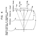
- Fig.4 is an illustrative drawing showing a forward prediction according to the present invention.
- the forward prediction is generalized by using integers N and M.
- a frame F N is a N-th frame when frames are successively counted from the frame O, and, likewise, a frame F M is a M-th frame.
- a forward prediction is made for the frame F N by using the frame O as a reference frame.
- a check is made whether the motion-vector-search range is sufficient for the frame F M to use the frame O as a reference frame. This check is made based on results which are obtained from the motion-vector search at the frame F N .
- a forward prediction for the frame F M requires a motion-vector component x detected between the frame F N and the frame O to satisfy: [(N ⁇ x lM )/M] ⁇ x ⁇ [(N ⁇ x uM )/M] where x lM and x uM are boundaries to define the motion-vector-search range used between the frame F M and the frame O.
- a forward prediction of the frame F M based on the reference frame O can be made, if motion vectors detected between the frame F N and the frame O satisfies the inequality (3) in a sufficient number so that a ratio of such motion vectors to all the motion vectors exceeds a predetermined threshold. In this manner, an enhancement of the prediction efficiency can be achieved.
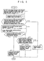
- Fig.5 is a flowchart of a process of changing the inter-frame distance according to an embodiment of the present invention.
- an inter-frame distance N for the forward prediction between the reference frame O and a predicted frame is set to 2
- an inter-frame-distance increment a is set to 1.
- motion vectors are searched for between the frame O and the frame F 2 .
- a check is made whether an accumulated differential E exceeds a predetermined amount.
- the accumulated differential E is a sum of absolute values of pixel-to-pixel differentials between the frame O and the frame F 2 . If the accumulated differential E exceeds the predetermined amount, the procedure goes to a step S7. Otherwise, the procedure goes to a step S4.
- the inter-frame distance N is maintained at 2. This is the case where a scene change is present.
- a check is made whether the ratio exceeds a predetermined threshold. If it does, the procedure goes to a step S6. Otherwise, the procedure goes to a step S8.
- the inter-frame distance is increased to N+a for subsequent forward predictions. (The inter-frame distance is increased to 3 according to the conditions set at the step S1.)
- the inter-frame distance is decreased to N-1 for subsequent forward predictions. (The inter-frame distance is decreased to 1 according to the conditions set at the step S1.)
- Fig.6 is an illustrative drawing for explaining a check on a motion-vector-search range of a bidirectional prediction according to the present invention.
- a forward prediction is currently made for the frame F N by using the reference frame O, which is provided N-frames before in a time dimension.
- a backward prediction of the frame B n for the bidirectional prediction is made based on the frame F N .
- a check is made whether a sufficient backward motion-vector-search range is maintained for the bidirectional prediction of the frame B n even when the forward-prediction is made for the frame F M .
- a backward prediction of the frame B n based on the frame F M requires a motion-vector component x detected between the frame F N and the frame O to satisfy: [(N ⁇ x nlb )/(M-n)] ⁇ x ⁇ [(N ⁇ x nub )/(M-n)] where x nlb and x nub are boundaries to define the backward motion-vector-search range used between the frame B n and the frame F M .
- N in the inequality (5) is the inter-frame distance between the frame F N and the frame O
- (M-n) is the inter-frame distance between the frame F M and the frame B n . That is, the range defined by the inequality (5) is equivalent to the backward motion-vector-search range defined by the boundaries x nlb and x nub after compensation for a difference of these inter-frame distances.
- a sufficient backward motion-vector-search range can be maintained even when the backward reference frame is changed from the frame F N to the frame F M , i.e., even when a frame forwardly predicted based on the reference frame O is changed from the frame F N to the frame F M .
- This sufficient backward motion-vector-search range can be maintained for any frames appearing immediately after the reference frame O which satisfies the inequality (5) together with the frame F N .
- a requirement is that a ratio of motion vectors satisfying the inequality (5) to all the motion vectors detected between the frame F N and the reference frame O exceed a predetermined threshold. As long as this requirement is met, the frame B n can be backwardly predicted based on the frame F M .
- a check as to whether the inter-frame distance can be increased may involve two decision making processes. First, a check may be made whether the vector-search range is sufficient for a forward prediction under an increased inter-frame distance. Then, another check may be made whether the vector-search range is sufficient for a backward prediction under the increased inter-frame distance. In the flowchart of Fig.5, for example, both of these two checks may be made at the step S4.
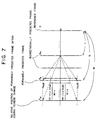
- Fig.7 is an illustrative drawing for explaining another check on a motion-vector-search range of the bidirectional prediction according to the present invention.
- a check shown in Fig.7 is used in the same manner as the check of Fig.6, and provides another method of deciding whether the motion-vector-search range is sufficient for a bidirectional prediction under an increased inter-frame distance.
- a forward prediction is currently made for the frame F N by using the reference frame O, which is provided N-frames before in a time dimension.
- a backward prediction of the frame B n for the bidirectional prediction is made based on the frame F N .
- a check is made whether a sufficient backward motion-vector-search range is maintained for the bidirectional prediction of the frame B n even when the forward-prediction is made for the frame F M .
- a backward prediction of the frame B n based on the frame F M requires a motion-vector component x detected between the frame B n and the frame F N to satisfy: [(N-n) ⁇ x nlb /(M-n)] ⁇ x ⁇ [(N-n) ⁇ x nub /(M-n)] where x nlb and x nub are boundaries to define the backward motion-vector-search range used between the frame B n and the frame F M .
- (N-n) in the inequality (6) is the inter-frame distance between the frame F N and the frame B n
- (M-n) is the inter-frame distance between the frame F M and the frame B n . That is, the range defined by the inequality (6) on the frame F N is equivalent to the backward motion-vector-search range defined by the boundaries x nlb and x nub on the frame F M after compensation for a difference of the inter-frame distances.
- a sufficient backward motion-vector-search range can be maintained even when the backward reference frame is changed from the frame F N to the frame F M , i.e., even when a frame forwardly predicted based on the reference frame O is changed from the frame F N to the frame F M .
- This sufficient backward motion-vector-search range can be maintained for any frames appearing immediately after motion-vector-search results satisfying the inequality (6) are obtained.
- a requirement is that a ratio of motion vectors satisfying the inequality (6) to all the motion vectors detected between the frame F N and the frame B n exceed a predetermined threshold. As long as this requirement is met, the frame B n can be backwardly predicted based on the frame F M .
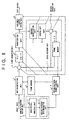
- Fig.8 is a block diagram of an embodiment of an image processing device according to the present invention.
- the image processing device of Fig.8 includes a motion-detection unit 1, a frame memory 2, a first operation unit 3, a DCT unit 4, a quantization unit 5, a variable-length coding unit 6, an inverse-quantization unit 7, an inverse-DCT unit 8, a second operation unit 9, a frame memory 10, a local-decoder unit 11, a statistical-analysis unit 12, a coding-pattern-determination unit 13, a coding-pattern-based control unit 14, and an analysis/determination unit 15.
- the frame memory 2 has a multi-bank structure to cope with different inter-frame distances which are used for detection of motion vectors.
- the frame memory 10 of the local-decoder unit 11 has two banks for storing pictures of the forward reference and the backward reference.
- the first operation unit 3 and the second operation unit 9 are in a through operation mode to pass data through when the intra-frame coding is applied. When the inter-frame coding is used, the first operation unit 3 operates as a subtracter, and the second operation unit 9 operates as an adder.
- Motion vectors detected by the motion-detection unit 1 are supplied to the statistical-analysis unit 12 of the coding-pattern-analysis/determination unit 15.
- the statistical-analysis unit 12 obtains statistics of the magnitude of the motion vectors.
- the coding-pattern-determination unit 13 determines a coding pattern of pictures by deciding the inter-frame distances for predictions, and notifies the coding-pattern-based control unit 14 of the determined coding pattern.
- the coding-pattern-based control unit 14 takes care of bank management of the frame memory 2 according to the inter-frame distances of the coding pattern.
- the coding-pattern-based control unit 14 is responsible for control of the first operation unit 3, the DCT unit 4, the quantization unit 5, the variable-length coding unit 6, the inverse-quantization unit 7, the inverse-DCT unit 8, the second operation unit 9, and the frame memory 10, according to the coding pattern.
- the first operation unit 3 and the second operation unit 9 are in a through operation mode to pass the data through.
- Picture information is DCT-transformed by the DCT unit 4, is quantized by the quantization unit 5, and is coded by the variable-length coding unit 6 before being output from the image processing device.
- the transformed and quantized picture information is inverse-quantized by the inverse-quantization unit 7, and is inverse-DCT-transformed by the inverse-DCT unit 8 before being stored in the frame memory 10.
- the motion-detection unit 1 reads from the frame memory 2 a previous frame in accordance with the inter-frame distance of the forward prediction, and compares this previous frame with the current frame to obtain motion vectors within a motion-vector-search range.
- the first operation unit 3 is controlled to work as a subtracter, and the second operation unit 9 is controlled to serve as an adder.
- the first operation unit 3 receives each block of the current frame from the motion-detection unit 1, and receives each corresponding block of the previous frame from the frame memory 10 in accordance with the detected motion vectors. Then, the first operation unit 3 takes block-to-block differentials between the current frame and the previous frame.
- the block-to-block differentials are coded by the DCT unit 4, the quantization unit 5, and the variable-length coding unit 6 to achieve inter-frame coding of the current frame.
- the second operation unit 9 obtains a sum between these differentials and the previous frame to obtain a predicted current frame, which is stored in the frame memory 10.
- the coding-pattern-based control unit 14 determines the number of B pictures inserted between a P picture and one of an I picture and a P picture.
- the B picture is predicted by using the forwardly-predicted P picture and the reference picture, which is one of an I picture and a previous P picture.
- pictures are generally provided in a partially reversed order at the time of coding.
- a picture sequence is I1B2P3 (i.e., a sequence of an intra picture, a bidirectionally predictive picture, and a forwardly predictive picture)
- an actual picture sequence for coding is I1P3B2.
- a first frame is coded as an I picture based on intra-frame coding, and, then, a third frame is coded as a P picture based on forward prediction. Finally, a second frame is coded based on bidirectional prediction by using the I picture and the P picture.
- a first mode is use of only the forward prediction.
- a second mode is use of only the backward prediction, and a third mode is use of both the backward prediction and the forward prediction.
- the best mode among these three mode is determined for each block, and is used for coding the respective block.
- the third mode using both the backward prediction and the forward prediction will be taken as an example for the sake of simplicity of explanation.
- the frame memory 2 is controlled by the coding-pattern-based control unit 14 based on the determined coding pattern, and the motion-detection unit 1 searches for motion vectors for the forward prediction and the backward prediction of the bidirectional prediction.
- the first operation unit 3 and the second operation unit 9 are controlled in the same manner as in the case of coding the P picture. Both banks for the forward prediction and the backward prediction are used in the frame memory 10.
- the motion-detection unit 1 reads from the frame memory 2 two reference frames for the forward prediction and the backward prediction, and compares the current frame with both the forward reference frame and the backward reference frame to obtain motion vectors within a motion-vector-search range.
- the first operation unit 3 receives each block of the current frame from the motion-detection unit 1, and receives each corresponding block of these two reference frames from the frame memory 10 in accordance with the detected motion vectors. Then, the first operation unit 3 takes block-to-block differentials between the current frame and an average of the two reference frames.
- the block-to-block differentials are coded by the DCT unit 4, the quantization unit 5, and the variable-length coding unit 6 to achieve bidirectionally predictive coding of the current frame.
- inter-frame differences between the reference frame and a frame to be predicted may be obtained to check the existence of a scene change.
- an absolute-value sum of the inter-frame differences between the reference frame and the frame to be predicted is obtained and compared with a predetermined value. This may be done by the motion-detection unit 1 and the statistical-analysis unit 12, for example. When this sum exceeds the predetermined value, the coding-pattern-based control unit 14 controls the other elements so as not to change the inter-frame distances.
- an absolute-value sum of differences between an original frame and a prediction-resulted frame may be obtained and compared with a predetermined value. This may be done by the coding-pattern-based control unit 14. When this sum exceeds the predetermined value, the coding-pattern-based control unit 14 controls the other elements to shorten the inter-frame distance between a reference frame and a frame to be predicted. In this manner, the inter-frame distance is reduced to regain an appropriate motion-vector-search range.
- the inter-frame distance is set at the possible maximum distance of the device at the start of the moving-picture coding of the present invention.
- the forward-prediction inter-frame distance M should start from 3 in the moving-picture coding.
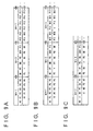
- Figs.9A through 9F are table charts for explaining the reason why the inter-frame distance should start from the possible maximum distance.
- the forward-prediction inter-frame distance M is changed once in every 6 frames.
- the top row shows the forward-prediction inter-frame distance M
- the middle row shows a sequence of I, P, and B pictures of the input picture information
- the bottom row shows a coded-picture sequence of I, P, and B pictures.
- a numeral after the symbol I, P, or B denote the frame number.
- I0, P1, P2, P3, P4, P5, and B6 represent an I picture of frame number 1, P pictures of frame numbers 2-5, and a B picture of frame number 6, respectively.
- Fig.9A shows a case in which an initial inter-frame distance for the forward prediction is 1.
- the forward-prediction inter-frame distance M (hereinafter, merely referred to as an inter-frame distance unless there is possibility of creating confusion) is changed from 1, 2, to 1, successively.
- a picture sequence of I0, P1, P2, P3, ⁇ is provided as the picture information at the start of the picture coding, a coded-picture sequence I0, P1, P2, P3, ⁇ is obtained with a delay of one frame period because of processing time for coding.
- Fig.9B shows a case in which an initial inter-frame distance for the forward prediction is 1.
- the forward-prediction inter-frame distance M is changed from 1, 2 to 3, successively.
- Fig.9C shows a case in which the inter-frame distance M is started at 2 and changed to 3.
- a coded frame is lacking during a certain frame period shown by the symbol x, and this occurs after the inter-frame distance M is changed from 2 to 3.
- Figs.9D through 9F show cases in which the inter-frame distance M is initially at the maximum distance of 3.
- Fig.9D shows a case in which the inter-frame distance M is changed from 3, 2, 3, 2, to 1, successively.
- the inter-frame distance M is changed from 3, 2, 1, 2, 1, to 2, successively.
- Fig.9F shows changes of the inter-frame distance M from 3, 2, 1, 2, 3, to 2.
- a picture sequence of B0, B1, I2, B3, ⁇ is provided as the picture information at the start of the picture coding, and a coded-picture sequence I2, B0, B1, ⁇ is obtained with a delay of three frame periods because I2 should be coded first ahead of B0 and B1.
- an initial value of the inter-frame distance is set to the possible maximum value, so that the delay of the coded-picture sequence is maximized from the beginning.
- a change in the inter-frame distance M does not bring about a frame period lacking a coded frame.
- Figs.9D through 9F show only the cases in which the inter-frame distance M is changed by ⁇ 1. However, even when the inter-frame distance M is changed by ⁇ 2, a maximum initial value of the inter-frame distance ensures that any frame period has a coded frame.
- an inter-frame distance with an appropriate motion-vector-search range is determined based on detected motion vectors by drawing on an assumed image characteristic that no abrupt change is present in picture motions within a short time period.
- an increase in the inter-frame distance is justified since an appropriate motion-vector-search range can be maintained after the increase.
- the inter-frame distance is stretched to increase the number of bidirectionally-predicted frames which have high prediction efficiency.
Landscapes
- Engineering & Computer Science (AREA)
- Multimedia (AREA)
- Signal Processing (AREA)
- Compression Or Coding Systems Of Tv Signals (AREA)
Claims (20)
- Verfahren zum Detektieren von Bewegungsvektoren innerhalb eines vorbestimmten Suchbereichs für eine Bewegungskompensations-Vorhersagecodierung, welches Verfahren gekennzeichnet ist durch die Schritte:a) Suchen nach ersten Bewegungsvektoren zwischen zwei Rahmen, die in einer Zeitdimension durch eine erste Rahmendistanz voneinander getrennt sind;b) Auswählen einer zweiten Rahmendistanz von zwei Rahmen, zwischen denen eine Bildbewegung durch zweite Bewegungsvektoren repräsentiert wird;c) Vornehmen einer Prüfung, ob der vorbestimmte Suchbereich einen vorbestimmten Prozentanteil der zweiten Bewegungsvektoren abdeckt, welche Prüfung die ersten Bewegungsvektoren als Schätzungen der zweiten Bewegungsvektoren nach einer Kompensation einer Differenz zwischen der ersten Rahmendistanz und der zweiten Rahmendistanz nutzt; undd) Entscheiden, basierend auf Ergebnissen der Prüfung, ob eine Rahmendistanz zur Vorhersage zu vergrößern ist.
- Verfahren nach Anspruch 1, dadurch gekennzeichnet, daßder Schritt a) einen Schritt zum Erhalten der ersten Bewegungsvektoren innerhalb des vorbestimmten Bereichs zwischen einem Bezugsrahmen (0) und einem vorwärts-vorhergesagten Rahmen (FN) aufweist, um den vorwärts-vorhergesagten Rahmen (FN) vorwärts-vorherzusagen; undder Schritt d) einen Schritt aufweist zum Entscheiden, basierend auf den Ergebnissen der Prüfung, ob die Rahmendistanz für eine Vorwärts-Vorhersage von der ersten Rahmendistanz (N) zur zweiten Rahmendistanz (M) zu vergrößern ist.
- Verfahren nach Anspruch 2, dadurch gekennzeichnet, daß der Schritt c) ferner einen Schritt zum Ändern einer Skala entweder des vorbestimmten Suchbereichs oder der ersten Bewegungsvektoren aufweist, um die Kompensation zu erreichen.
- Verfahren nach Anspruch 3, dadurch gekennzeichnet, daß der Schritt c) ferner einen Schritt zum Ändern der Skala durch ein Verhältnis zwischen der ersten Rahmendistanz (N) und der zweiten Rahmendistanz (M) aufweist.
- Verfahren nach Anspruch 3, dadurch gekennzeichnet, daß der Schritt c) die Schritte umfaßt:c1) Erhalten eines Prozentanteils der ersten Vektoren (x, y), diec2) Prüfen, ob der Prozentanteil den vorbestimmten Prozentanteil übersteigt.
- Verfahren nach Anspruch 1, dadurch gekennzeichnet, daßder Schritt a) einen Schritt zum Erhalten der ersten Bewegungsvektoren zwischen einem Bezugsrahmen (0) und einem vorwärts-vorhergesagten Rahmen (FN) aufweist, um den vorwärts-vorhergesagten Rahmen (FN) vorwärts-vorherzusagen,der Schritt b) einen Schritt zum Auswählen der zweiten Rahmendistanz aufweist, um einen bidirektional vorhergesagten Rahmen (Bn) basierend auf einem Rückwärts-Bezugsrahmen (FM) rückwärts-vorherzusagen, undder Schritt d) einen Schritt aufweist zum Entscheiden, basierend auf den Ergebnissen der Prüfung, ob die Rahmendistanz für eine Vorwärts-Vorhersage von der ersten Rahmendistanz (N) zu vergrößern ist, so daß eine Rahmendistanz für eine Rückwärts-Vorhersage auf die zweite Rahmendistanz (M) vergrößert wird.
- Verfahren nach Anspruch 6, dadurch gekennzeichnet, daß der Schritt c) ferner einen Schritt zum Ändern einer Skala von entweder des vorbestimmten Suchbereichs oder der ersten Bewegungsvektoren aufweist, um die Kompensation zu erreichen.
- Verfahren nach Anspruch 7, dadurch gekennzeichnet, daß der Schritt c) ferner einen Schritt zum Ändern der Skala durch ein Verhältnis zwischen der ersten Rahmendistanz (N) und der zweiten Rahmendistanz (M) aufweist.
- Verfahren nach Anspruch 1, dadurch gekennzeichnet, daßder Schritt a) einen Schritt zum Erhalten der ersten Bewegungsvektoren zwischen einem Rückwärts-Bezugsrahmen und einem bidirektional vorhergesagten Rahmen (Bn) aufweist, um den bidirektional vorhergesagten Rahmen (Bn) rückwärts-vorherzusagen,der Schritt b) einen Schritt zum Auswählen der zweiten Rahmendistanz aufweist, um einen bidirektional vorhergesagten Rahmen basierend auf einem Rückwärts-Bezugsrahmen rückwärtsvorherzusagen, undder Schritt d) einen Schritt aufweist zum Entscheiden, basierend auf den Ergebnissen der Prüfung, ob die Rahmendistanz für eine Vorwärts-Vorhersage zu vergrößern ist, so daß eine Rahmendistanz für eine Rückwärts-Vorhersage von der ersten Rahmendistanz zur zweiten Rahmendistanz vergrößert wird.
- Verfahren nach Anspruch 9, dadurch gekennzeichnet, daß der Schritt c) ferner einen Schritt zum Ändern einer Skala entweder des vorbestimmten Suchbereichs oder der ersten Bewegungsvektoren aufweist, um die Kompensation zu erreichen.
- Verfahren nach Anspruch 10, dadurch gekennzeichnet, daß der Schritt c) ferner einen Schritt zum Ändern der Skala durch ein Verhältnis zwischen der ersten Rahmendistanz und der zweiten Rahmendistanz aufweist.
- Verfahren nach Anspruch 2, ferner gekennzeichnet durch die Schritte:e) Erhalten eines Prozentanteils der ersten Vektoren (x, y), dief) Prüfen, ob der Prozentanteil einen vorbestimmten Prozentanteil übersteigt.
- Verfahren nach Anspruch 2, ferner gekennzeichnet durch die Schritte:e) Erhalten dritter Vektoren zwischen einem Rückwärts-Bezugsrahmen und einem bidirektional vorhergesagten Rahmen, der rückwärts-vorhergesagt wird basierend auf dem Rückwärts-Bezugsrahmen und von einem Vorwärts-Bezugsrahmen um eine Rahmendistanz n getrennt ist;f) Erhalten eines Prozentanteils der dritten Vektoren (x, y), dieg) Prüfen, ob der Prozentanteil einen vorbestimmten Prozentanteil übersteigt.
- Verfahren nach Anspruch 2, ferner gekennzeichnet durch die Schritte:e) Erhalten einer Differenz zwischen einem vorwärts-vorhergesagten Rahmen (FN) und einem entsprechenden Rahmen, der basierend auf einer Vorwärts-Vorhersage erhalten wird;f) Prüfen, ob die Differenz einen vorbestimmten Betrag überschreitet; undg) Verkürzen der Rahmendistanz für die Vorwärts-Vorhersage, wenn die Differenz den vorbestimmten Betrag überschreitet.
- Verfahren nach Anspruch 2, ferner gekennzeichnet durch die Schritte:e) Erhalten einer Differenz zwischen einem bidirektional vorhergesagten Rahmen und einem entsprechenden Rahmen, der basierend auf einer bidirektionalen Vorhersage erhalten wird;f) Prüfen, ob die Differenz einen vorbestimmten Betrag überschreitet; undg) Verkürzen der Rahmendistanz für die Vorwärts-Vorhersage, wenn die Differenz den vorbestimmten Betrag überschreitet.
- Verfahren nach Anspruch 2, ferner gekennzeichnet durch die Schritte:e) Erhalten einer Differenz zwischen dem Bezugsrahmen (O) und dem vorwärts-vorhergesagten Rahmen (FN);f) Prüfen, ob die Differenz einen vorbestimmten Betrag überschreitet; undg) Überspringen des Schritts c) und Beibehalten der Rahmendistanz für die Vorwärts-Vorhersage, wenn die Differenz den vorbestimmten Betrag überschreitet.
- Verfahren nach Anspruch 2, ferner gekennzeichnet durch die Schritte:e) Bestimmen einer möglichen maximalen Rahmendistanz für die Vorwärts-Vorhersage; undf) Beginnen der Bewegungskompensations-Vorhersagecodierung, indem die mögliche maximale Rahmendistanz für die Vorwärts-Vorhersage verwendet wird.
- Vorrichtung zum Detektieren von Bewegungsvektoren innerhalb eines vorbestimmten Suchbereichs für eine Bewegungskompensations-Vorhersagecodierung, welche Vorrichtung gekennzeichnet ist durch:Bewegungsdektektionsmittel (1) zum Suchen nach ersten Bewegungsvektoren zwischen zwei Rahmen, die in einer Zeitdimension durch eine erste Rahmendistanz voneinander getrennt sind;Analyse-und-Bestimmungs-Mittel (15) zum Auswählen eines einer zweiten Rahmendistanz von zwei Rahmen, zwischen denen eine Bildbewegung durch zweite Bewegungsvektoren repräsentiert wird, und zum Vornehmen einer Prüfung, ob der vorbestimmte Suchbereich einen vorbestimmten Prozentanteil der zweiten Bewegungsvektoren abdeckt, welche Prüfung die ersten Bewegungsvektoren als Schätzungen der zweiten Bewegungsvektoren nach einer Kompensation einer Differenz zwischen der ersten Rahmendistanz und der zweiten Rahmendistanz nutzt;Steuermittel (14) zum Steuern, basierend auf den Ergebnissen der Prüfung, einer Änderung in einer Rahmendistanz für eine Vorhersage.
- Vorrichtung nach Anspruch 18, dadurch gekennzeichnet, daß das Bewegungs-Detektionsmittel (1) Mittel zum Erhalten der ersten Bewegungsvektoren zwischen einem Bezugsrahmen und einem vorwärts-vorhergesagten Rahmen aufweist, um den vorwärts-vorhergesagten Rahmen vorwärts-vorherzusagen, und das Steuermittel (14) Mittel zum Vergrößern der Rahmendistanz für eine Vorwärts-Vorhersage, basierend auf den Ergebnissen der Prüfung, von der ersten Rahmendistanz zur zweiten Rahmendistanz aufweist.
- Vorrichtung nach Anspruch 19, dadurch gekennzeichnet, daß das Analyse-und-Bestimmungs-Mittel (15) ferner aufweist Mittel zum Vornehmen einer Prüfung, ob ein Suchbereich für eine Rückwärts-Vorhersage ausreicht, nachdem die Rahmendistanz für die Vorwärts-Vorhersage vergrößert ist, welche Prüfung die ersten Bewegungsvektoren als Schätzungen von in der Rückwärts-Vorhersage verwendeten Bewegungsvektoren nutzt.
Applications Claiming Priority (3)
| Application Number | Priority Date | Filing Date | Title |
|---|---|---|---|
| JP10657796A JP3876392B2 (ja) | 1996-04-26 | 1996-04-26 | 動きベクトル探索方法 |
| JP106577/96 | 1996-04-26 | ||
| JP10657796 | 1996-04-26 |
Publications (3)
| Publication Number | Publication Date |
|---|---|
| EP0804034A2 EP0804034A2 (de) | 1997-10-29 |
| EP0804034A3 EP0804034A3 (de) | 1998-05-20 |
| EP0804034B1 true EP0804034B1 (de) | 2002-01-23 |
Family
ID=14437090
Family Applications (1)
| Application Number | Title | Priority Date | Filing Date |
|---|---|---|---|
| EP19960306812 Expired - Lifetime EP0804034B1 (de) | 1996-04-26 | 1996-09-19 | Verfahren und Vorrichtung zur Detektion von Bewegungsvektoren |
Country Status (3)
| Country | Link |
|---|---|
| US (1) | US5894526A (de) |
| EP (1) | EP0804034B1 (de) |
| JP (1) | JP3876392B2 (de) |
Families Citing this family (42)
| Publication number | Priority date | Publication date | Assignee | Title |
|---|---|---|---|---|
| JP3930935B2 (ja) * | 1997-02-28 | 2007-06-13 | 三菱電機株式会社 | 画像処理装置 |
| JPH10262258A (ja) * | 1997-03-19 | 1998-09-29 | Sony Corp | 画像符号化装置及び方法 |
| JP3604864B2 (ja) * | 1997-04-25 | 2004-12-22 | シャープ株式会社 | 動画像符号化装置 |
| JPH10336668A (ja) * | 1997-06-02 | 1998-12-18 | Sharp Corp | 動きベクトル検出装置 |
| JP3185763B2 (ja) * | 1998-07-13 | 2001-07-11 | 日本電気株式会社 | 動画像符号化装置 |
| TW444507B (en) | 1998-10-22 | 2001-07-01 | Sony Corp | Detecting method and device for motion vector |
| US6573905B1 (en) | 1999-11-09 | 2003-06-03 | Broadcom Corporation | Video and graphics system with parallel processing of graphics windows |
| US6738072B1 (en) * | 1998-11-09 | 2004-05-18 | Broadcom Corporation | Graphics display system with anti-flutter filtering and vertical scaling feature |
| US6661422B1 (en) * | 1998-11-09 | 2003-12-09 | Broadcom Corporation | Video and graphics system with MPEG specific data transfer commands |
| US7446774B1 (en) | 1998-11-09 | 2008-11-04 | Broadcom Corporation | Video and graphics system with an integrated system bridge controller |
| US6798420B1 (en) | 1998-11-09 | 2004-09-28 | Broadcom Corporation | Video and graphics system with a single-port RAM |
| US6636222B1 (en) * | 1999-11-09 | 2003-10-21 | Broadcom Corporation | Video and graphics system with an MPEG video decoder for concurrent multi-row decoding |
| US6853385B1 (en) | 1999-11-09 | 2005-02-08 | Broadcom Corporation | Video, audio and graphics decode, composite and display system |
| US7982740B2 (en) | 1998-11-09 | 2011-07-19 | Broadcom Corporation | Low resolution graphics mode support using window descriptors |
| US6768774B1 (en) * | 1998-11-09 | 2004-07-27 | Broadcom Corporation | Video and graphics system with video scaling |
| US6621936B1 (en) | 1999-02-12 | 2003-09-16 | Sony Corporation | Method and apparatus for spatial class reduction |
| US6418548B1 (en) | 1999-02-12 | 2002-07-09 | Sony Corporation | Method and apparatus for preprocessing for peripheral erroneous data |
| US6519369B1 (en) | 1999-02-12 | 2003-02-11 | Sony Corporation | Method and apparatus for filter tap expansion |
| US6591398B1 (en) | 1999-02-12 | 2003-07-08 | Sony Corporation | Multiple processing system |
| JP3531532B2 (ja) | 1999-05-18 | 2004-05-31 | 日本電気株式会社 | 動画像符号化装置、及び方法 |
| US6522785B1 (en) | 1999-09-24 | 2003-02-18 | Sony Corporation | Classified adaptive error recovery method and apparatus |
| JP3757088B2 (ja) | 1999-10-26 | 2006-03-22 | 日本電気株式会社 | 動画像符号化装置および方法 |
| US6975324B1 (en) | 1999-11-09 | 2005-12-13 | Broadcom Corporation | Video and graphics system with a video transport processor |
| US6754371B1 (en) * | 1999-12-07 | 2004-06-22 | Sony Corporation | Method and apparatus for past and future motion classification |
| JP2002084544A (ja) * | 2000-09-06 | 2002-03-22 | Mitsubishi Electric Corp | 動画像符号化装置および動画像符号化方法 |
| US20020039138A1 (en) * | 2000-09-29 | 2002-04-04 | Edelson Steven D. | Method and apparatus for automatically adjusting video panning and zoom rates |
| US7616690B2 (en) | 2000-10-31 | 2009-11-10 | Imec | Method and apparatus for adaptive encoding framed data sequences |
| EP1204279A3 (de) * | 2000-10-31 | 2002-05-15 | Interuniversitair Microelektronica Centrum Vzw | Verfahren und Vorrichtung für die adaptive Kodierung von eingerahmten Datensequenzen |
| EP1202579A1 (de) * | 2000-10-31 | 2002-05-02 | Interuniversitair Microelektronica Centrum Vzw | Verfahren und Vorrichtung für die adaptive Kodierung von Einzelbilddatensequenzen |
| US6700934B2 (en) | 2001-03-14 | 2004-03-02 | Redrock Semiconductor, Ltd. | Error detection using a maximum distance among four block-motion-vectors in a macroblock in a corrupted MPEG-4 bitstream |
| US6925125B2 (en) * | 2002-01-09 | 2005-08-02 | Hiroshi Akimoto | Enhanced aperture problem solving method using displaced center quadtree adaptive partitioning |
| US7088773B2 (en) * | 2002-01-17 | 2006-08-08 | Sony Corporation | Motion segmentation system with multi-frame hypothesis tracking |
| WO2004014085A1 (ja) * | 2002-08-05 | 2004-02-12 | Matsushita Electric Industrial Co., Ltd. | データ処理装置およびデータ処理方法 |
| US20040091047A1 (en) * | 2002-11-11 | 2004-05-13 | Sony Corporation | Method and apparatus for nonlinear multiple motion model and moving boundary extraction |
| JP2004179687A (ja) * | 2002-11-22 | 2004-06-24 | Toshiba Corp | 動画像符号化/復号化方法及び装置 |
| US8063916B2 (en) | 2003-10-22 | 2011-11-22 | Broadcom Corporation | Graphics layer reduction for video composition |
| CN100373952C (zh) * | 2004-06-15 | 2008-03-05 | 中兴通讯股份有限公司 | 一种基于mpeg-4的视频对象快速运动估值方法 |
| US8275049B2 (en) * | 2006-06-16 | 2012-09-25 | Via Technologies, Inc. | Systems and methods of improved motion estimation using a graphics processing unit |
| TWI444047B (zh) * | 2006-06-16 | 2014-07-01 | Via Tech Inc | 用於視訊解碼的去方塊效應濾波器、視訊解碼器與圖形處理單元 |
| US9319708B2 (en) * | 2006-06-16 | 2016-04-19 | Via Technologies, Inc. | Systems and methods of improved motion estimation using a graphics processing unit |
| TW201121335A (en) * | 2009-12-02 | 2011-06-16 | Sunplus Core Technology Co Ltd | Method and apparatus for adaptively determining compression modes to compress frames |
| JP6527460B2 (ja) * | 2015-12-25 | 2019-06-05 | 日本電信電話株式会社 | 映像符号化装置、映像符号化方法及び映像符号化プログラム |
Family Cites Families (10)
| Publication number | Priority date | Publication date | Assignee | Title |
|---|---|---|---|---|
| FR2648254B2 (fr) * | 1988-09-23 | 1991-08-30 | Thomson Csf | Procede et dispositif d'estimation de mouvement dans une sequence d'images animees |
| US5467136A (en) * | 1991-05-31 | 1995-11-14 | Kabushiki Kaisha Toshiba | Video decoder for determining a motion vector from a scaled vector and a difference vector |
| JPH0595540A (ja) * | 1991-09-30 | 1993-04-16 | Sony Corp | 動画像符号化装置 |
| CA2079434A1 (en) * | 1991-09-30 | 1993-03-31 | Derek Andrew | Motion vector estimation, motion picture encoding and storage |
| JPH06153146A (ja) * | 1992-11-04 | 1994-05-31 | Matsushita Electric Ind Co Ltd | 動画像のシーンチェンジ検出装置および編集装置 |
| KR0128860B1 (ko) * | 1993-07-16 | 1998-04-10 | 배순훈 | 저비트율의 영상전화 시스템의 부호화장치 |
| US5592226A (en) * | 1994-01-26 | 1997-01-07 | Btg Usa Inc. | Method and apparatus for video data compression using temporally adaptive motion interpolation |
| JPH0846969A (ja) * | 1994-07-26 | 1996-02-16 | Mitsubishi Electric Corp | 映像信号符号化方式 |
| US5650829A (en) * | 1994-04-21 | 1997-07-22 | Sanyo Electric Co., Ltd. | Motion video coding systems with motion vector detection |
| KR0171145B1 (ko) * | 1995-03-20 | 1999-03-20 | 배순훈 | 이미지 부호화 시스템용 움직임 보상 장치 |
-
1996
- 1996-04-26 JP JP10657796A patent/JP3876392B2/ja not_active Expired - Fee Related
- 1996-09-19 EP EP19960306812 patent/EP0804034B1/de not_active Expired - Lifetime
- 1996-09-20 US US08/716,877 patent/US5894526A/en not_active Expired - Lifetime
Also Published As
| Publication number | Publication date |
|---|---|
| US5894526A (en) | 1999-04-13 |
| JP3876392B2 (ja) | 2007-01-31 |
| EP0804034A2 (de) | 1997-10-29 |
| JPH09294266A (ja) | 1997-11-11 |
| EP0804034A3 (de) | 1998-05-20 |
Similar Documents
| Publication | Publication Date | Title |
|---|---|---|
| EP0804034B1 (de) | Verfahren und Vorrichtung zur Detektion von Bewegungsvektoren | |
| KR100683849B1 (ko) | 디지털 영상 안정화기능을 갖는 디코더 및 디지털영상안정화방법 | |
| US5859668A (en) | Prediction mode selecting device in moving image coder | |
| US5854658A (en) | Statistical multiplexing system which encodes a sequence of video images using a plurality of video encoders | |
| US6057893A (en) | Picture encoding method, picture encoding apparatus, picture transmitting method and picture recording medium | |
| Lee et al. | Temporally adaptive motion interpolation exploiting temporal masking in visual perception | |
| US5841475A (en) | Image decoding with dedicated bidirectional picture storage and reduced memory requirements | |
| US6591015B1 (en) | Video coding method and apparatus with motion compensation and motion vector estimator | |
| US6542642B2 (en) | Image coding process and motion detecting process using bidirectional prediction | |
| US5689307A (en) | Encoding and decoding systems for transmitting moving pictures | |
| US6867714B2 (en) | Method and apparatus for estimating a motion using a hierarchical search and an image encoding system adopting the method and apparatus | |
| US20060120458A1 (en) | Video encoding apparatus and method and video encoding mode converting apparatus and method | |
| US20080112486A1 (en) | Encoding apparatus and encoding method | |
| US20050123039A1 (en) | Motion estimation method for motion picture encoding and recording medium having program recorded thereon to implement the motion estimation method | |
| EP1503598A1 (de) | Verfahren, System und Vorrichtungen zur Detektion von Bewegungsvektoren | |
| US6950465B1 (en) | Video coding by adaptively controlling the interval between successive predictive-coded frames according to magnitude of motion | |
| JP3426668B2 (ja) | 動画像符号化方法 | |
| US6591014B1 (en) | Apparatus for coding moving picture | |
| US20050005301A1 (en) | Method and apparatus for determining motion compensation mode | |
| US6968087B1 (en) | Encoding apparatus, encoding method, and storage medium | |
| EP1440583A2 (de) | Verfahren und system zum überspringen der decodierung überlagerter videobereiche | |
| US8606024B2 (en) | Compression-coding device and decompression-decoding device | |
| JP3428332B2 (ja) | 画像符号化方法及び装置、並びに画像伝送方法 | |
| JP3700801B2 (ja) | 画像符号化装置および画像符号化方法 | |
| JP2003102007A (ja) | 信号処理装置 |
Legal Events
| Date | Code | Title | Description |
|---|---|---|---|
| PUAI | Public reference made under article 153(3) epc to a published international application that has entered the european phase |
Free format text: ORIGINAL CODE: 0009012 |
|
| AK | Designated contracting states |
Kind code of ref document: A2 Designated state(s): FR GB |
|
| PUAL | Search report despatched |
Free format text: ORIGINAL CODE: 0009013 |
|
| AK | Designated contracting states |
Kind code of ref document: A3 Designated state(s): FR GB |
|
| 17P | Request for examination filed |
Effective date: 19981116 |
|
| GRAG | Despatch of communication of intention to grant |
Free format text: ORIGINAL CODE: EPIDOS AGRA |
|
| 17Q | First examination report despatched |
Effective date: 20010320 |
|
| GRAG | Despatch of communication of intention to grant |
Free format text: ORIGINAL CODE: EPIDOS AGRA |
|
| GRAH | Despatch of communication of intention to grant a patent |
Free format text: ORIGINAL CODE: EPIDOS IGRA |
|
| GRAH | Despatch of communication of intention to grant a patent |
Free format text: ORIGINAL CODE: EPIDOS IGRA |
|
| GRAA | (expected) grant |
Free format text: ORIGINAL CODE: 0009210 |
|
| REG | Reference to a national code |
Ref country code: GB Ref legal event code: IF02 |
|
| AK | Designated contracting states |
Kind code of ref document: B1 Designated state(s): FR GB |
|
| ET | Fr: translation filed | ||
| PLBE | No opposition filed within time limit |
Free format text: ORIGINAL CODE: 0009261 |
|
| STAA | Information on the status of an ep patent application or granted ep patent |
Free format text: STATUS: NO OPPOSITION FILED WITHIN TIME LIMIT |
|
| 26N | No opposition filed | ||
| PGFP | Annual fee paid to national office [announced via postgrant information from national office to epo] |
Ref country code: GB Payment date: 20130918 Year of fee payment: 18 Ref country code: FR Payment date: 20130910 Year of fee payment: 18 |
|
| GBPC | Gb: european patent ceased through non-payment of renewal fee |
Effective date: 20140919 |
|
| REG | Reference to a national code |
Ref country code: FR Ref legal event code: ST Effective date: 20150529 |
|
| PG25 | Lapsed in a contracting state [announced via postgrant information from national office to epo] |
Ref country code: GB Free format text: LAPSE BECAUSE OF NON-PAYMENT OF DUE FEES Effective date: 20140919 |
|
| PG25 | Lapsed in a contracting state [announced via postgrant information from national office to epo] |
Ref country code: FR Free format text: LAPSE BECAUSE OF NON-PAYMENT OF DUE FEES Effective date: 20140930 |