EP0804002A1 - Verfahren und Vorrichtung zur Erkennung der Anwesenheit eines Kodewortes innerhalb eines ankommenden Datenwortes - Google Patents
Verfahren und Vorrichtung zur Erkennung der Anwesenheit eines Kodewortes innerhalb eines ankommenden Datenwortes Download PDFInfo
- Publication number
- EP0804002A1 EP0804002A1 EP96201105A EP96201105A EP0804002A1 EP 0804002 A1 EP0804002 A1 EP 0804002A1 EP 96201105 A EP96201105 A EP 96201105A EP 96201105 A EP96201105 A EP 96201105A EP 0804002 A1 EP0804002 A1 EP 0804002A1
- Authority
- EP
- European Patent Office
- Prior art keywords
- codeword
- alternative
- subword
- dataword
- cod
- Prior art date
- Legal status (The legal status is an assumption and is not a legal conclusion. Google has not performed a legal analysis and makes no representation as to the accuracy of the status listed.)
- Granted
Links
- 238000000034 method Methods 0.000 title claims abstract description 24
- 238000004891 communication Methods 0.000 claims abstract description 9
- 230000002596 correlated effect Effects 0.000 claims description 10
- 239000000835 fiber Substances 0.000 claims description 5
- 238000001514 detection method Methods 0.000 description 13
- 102100040998 Conserved oligomeric Golgi complex subunit 6 Human genes 0.000 description 8
- 101000748957 Homo sapiens Conserved oligomeric Golgi complex subunit 6 Proteins 0.000 description 8
- 201000000465 X-linked cone-rod dystrophy 2 Diseases 0.000 description 8
- 101000876012 Homo sapiens Conserved oligomeric Golgi complex subunit 4 Proteins 0.000 description 6
- 101001104102 Homo sapiens X-linked retinitis pigmentosa GTPase regulator Proteins 0.000 description 6
- 208000036448 RPGR-related retinopathy Diseases 0.000 description 6
- 201000000467 X-linked cone-rod dystrophy 1 Diseases 0.000 description 6
- 102100040092 X-linked retinitis pigmentosa GTPase regulator Human genes 0.000 description 6
- 229910004438 SUB2 Inorganic materials 0.000 description 5
- 101100311330 Schizosaccharomyces pombe (strain 972 / ATCC 24843) uap56 gene Proteins 0.000 description 5
- 101150018444 sub2 gene Proteins 0.000 description 5
- 102100036464 Activated RNA polymerase II transcriptional coactivator p15 Human genes 0.000 description 4
- 101000713904 Homo sapiens Activated RNA polymerase II transcriptional coactivator p15 Proteins 0.000 description 4
- 229910004444 SUB1 Inorganic materials 0.000 description 4
- 238000012790 confirmation Methods 0.000 description 4
- 239000013598 vector Substances 0.000 description 4
- 230000005540 biological transmission Effects 0.000 description 3
- 238000013459 approach Methods 0.000 description 2
- 238000004377 microelectronic Methods 0.000 description 2
- 238000004458 analytical method Methods 0.000 description 1
- 230000001427 coherent effect Effects 0.000 description 1
- 230000001419 dependent effect Effects 0.000 description 1
- 238000009432 framing Methods 0.000 description 1
- 230000002452 interceptive effect Effects 0.000 description 1
- 230000000737 periodic effect Effects 0.000 description 1
- 230000010363 phase shift Effects 0.000 description 1
- 238000012545 processing Methods 0.000 description 1
Images
Classifications
-
- H—ELECTRICITY
- H04—ELECTRIC COMMUNICATION TECHNIQUE
- H04L—TRANSMISSION OF DIGITAL INFORMATION, e.g. TELEGRAPHIC COMMUNICATION
- H04L7/00—Arrangements for synchronising receiver with transmitter
- H04L7/04—Speed or phase control by synchronisation signals
- H04L7/041—Speed or phase control by synchronisation signals using special codes as synchronising signal
- H04L7/042—Detectors therefor, e.g. correlators, state machines
Definitions
- the present invention relates to a method to detect the presence of a codeword in an incoming dataword as described in the preamble of claim 1, a device realizing said method as described in the preamble of claim 5 and a receiver and a communication system including this device as described in the preambles of claims 9 and 10 respectively.
- the disadvantage of the method used in this known receiver is that the codeword must be relatively long to keep the probability of false detection low.
- the complexity of a correlator included in the receiver and usually used for this approach is proportional to the length of the codeword. As a result, the correlator must be relatively complicated and requires a lot of hardware.
- An object of the present invention is to provide a device and a method to detect the presence of a codeword in an incoming dataword with a low probability of false detection such as the above known receivers but which have not the above drawback, i.e. which require less hardware than the latter receivers.
- the object is achieved by means of the method described in claim 1, realised with the device described in claim 5, used in a hybrid fiber coax network as described in claims 4 and 8 and a receiver and a communication system as described in claims 9 and 10 respectively.
- the first subcodeword can be relatively short compared to the codeword used in the known method.
- the low level of false detection is obtained by combining the result of the first interpretion of a first subword with an alternative interpretion of an alternative subword.
- the alternative subword must at least partially overlap the first subword in order to have interpreted at least one symbol included in the first subword for at least two times, which contributes to the low level of false detection of the codeword.
- This preferred embodiment is used in a receiver with the general objective to receive and to decode a sequence of quadriphase shift keying QPSK modulated bursts which are transmitted from a number of remote stations over a shared medium e.g. coax network (Hybrid Fiber Coax network HFC) to a central station which includes this receiver.
- a shared medium e.g. coax network (Hybrid Fiber Coax network HFC)
- This multipoint to point transmission is working following the principle of time division multiple access (TDMA).
- TDMA time division multiple access
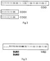
- the predefined symbol sequence of the codeword COD which is used for this preferred embodiment is shown in figure 2.
- a first subcodeword COD1 and a second subcodeword COD2 are both defined as part of this codeword COD and are in this preferred embodiment totally overlapping each other. The reason why this predefined symbol sequence of this codeword COD and wordlength of these subcodewords COD1, COD2 are choosen in this way will become apparent in the following paragraphs.
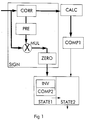
- the device to detect the presence of a codeword shown in figure 1 includes three main blocks which are not shown in figure 1 in order not to overload the figure but which are mentioned in this description to explain better the structure of the device.
- the first main block includes a correlator CORR, a calculator CALC and a comparator COMP1.
- the correlator CORR which is realised by a phase matched filter is coupled to an input of the device of the invention and to the calculator CALC.
- the calculator CALC is coupled to the comparator COMP1.
- the second main block includes sign detecting means SIGN, an inversion detector INV and comparator means COMP2.
- the sign detecting means SIGN includes the same correlator CORR as from the first main block, a phase reference estimator PRE, a complex multiplexer MUL and a zero crossing device ZERO.
- the correlator CORR is coupled to the phase reference estimator PRE which is coupled to the complex multiplexer MUL.
- the complex multiplexer MUL which is coupled to the same input of the device of the invention as to which the correlator CORR is coupled is also coupled to the zero crossing device ZERO.
- the zero crossing device ZERO is coupled to the inversion detector INV which is coupled to the comparator means COMP2.
- the inversion detector INV and the comparator means COMP2 are realised by a first part STATE1 of a state machine.
- the third main block is realised by a second part STATE2 of the same state machine which is also coupled to the comparator COMP1 of the first main block and an output of the device of the invention.
- FIG. 1 shows an Incoming dataword WRD which includes a first subword SUB1 and second subword SUB2. These subwords SUB1, SUB2 have a predetermined length which is equal to the length of the respectively subcodewords COD1, COD2 and which are in this preferred embodiment equal to each other and located on the same place in reference to the incoming dataword WRD. In order not to overload figure 1 the incoming data word WRD is not shown on figure 1.
- the first subword SUB1 is interpreted by the first main block in order to check the accomplishment of a first condition.
- the correlator CORR calculates the correlation of the first subword SUB1 presented to the correlator CORR with the first subcodeword COD1 and provides a correlated signal which is indicative for the result of the correlation.
- the filter coefficients of the phase match filter realising the correlation and the predetermined first subcodeword COD1 are optimised and selected in order to provide a correlated signal with an optimal signal to noise ratio and whereof the powervalue, dependent of the known powerlevel of the incoming dataword and the shape of the correlated signal, is a good parameter for the measure of correlation.
- the input of this preferred embodiment represents two terminals : one terminal for the real part and one terminal for the imaginary part of the incoming signal. It will be obvious for a person skilled in the art that as well the real part as the imaginary part of the incoming dataword are correlated in the correlator CORR and that the correlator CORR provides also a complex number wherof the powervalue is calculated by adding the squares of the real and the imaginary part of the complex number.
- the comparator COMP1 compares the calculated powervalue to a predetermined thresholdvalue and decides that the first condition is accomplished when the powervalue exceeds this predetermined thresholdvalue. At that time a first control signal is generated and provided to the third main block i.e. the second part of the state machine STATE2.
- the predetermined thresholdvalue was calculated out of the powerlevel of the correlated signal provided by correlating the first subcodeword, as incoming subword, with itself and the known powerlevel of that first subcodeword as incoming datword. This predetermined optimised thresholdvalue was adjusted before starting the detection of the presence of a codeword.
- the second subword SUB2 is interpreted by the second main block in order to check the accomplishment of a second condition.
- the sign detecting means SIGN determines the signs of the consecutive symbols of the second subword SUB2 i.e. the phases of the vectors representing the constellations of the QPSK modulated symbols in a vector space. So, the correlated signal presented by the correlator CORR is also used by the phase reference estimator PRE to make an initial reference phase estimation and to provide a complex reference phase.
- the complex multiplexer MUL performs a complex multiplication of the incoming subword SUB2 which is a complex dataword with this complex reference phase. The need for this processing step originates from the phase difference between the phase of the carrier of the transmitter included in the remote station and the phase of the carrier of the receiver included in the central station.
- phase difference is eliminated and complex consecutive symbols are provided to the zero crossing device ZERO which returns the sign of the real part of these complex consecutive symbols being plus (+) or minus (-).
- These signs which indicate in fact the phases of the vectors representing the constellations of antipodal QPSK modulated symbols in a vector space e.g. 11 and 00 are provided to the inversion detector INV which analyses the sequence of these signs and detects the inversions between the signs.
- these inversions are compared by the comparator means COMP2 with the expected inversions of the consecutive symbols of the second subcodeword COD2 and the comparator means COMP2 decides that a second condition is accomplished when the inversions match the expected inversions.
- the codeword COD and length of the second subcodeword COD2 are well choosen as shown in figure 2 the first expected inversion of the second subcodeword COD2 lies between the last but one QPSK symbol and the last QPSK symbol.
- a second control signal is generated and provided to the third main block i.e. second part of the state machine STATE2.
- this third main block i.e. second part of the state machine STATE2 combines the results of the first main block and the second main block and decides on reception of the first control signal and the second control signal that the codeword COD has been detected.
- the third main block generates a third control signal to confirm the detection of the presence of a codeword and provides it to an output of the device of the invention.
- the remaining part of the incoming dataword is interpreted by the second main block by comparing the inversions of the signs of the consecutive symbols of the remaining part of the incoming dataword with the expected inversion of the signs of the remaining part of the codeword in order to decide that a true total codeword until the last QPSK symbol is received when the inversions match.
- the synchronisation process is performed e.g. upon reception of a confirmation of the detection of the presence of the codeword the phase reference estimator PRE blocks the actual complex reference phase which is in fact the estimated phase at the time of the first inversion of the incoming dataword and a coherent detection or differential detection can be performed.
- a QPSK decoder (not shown) starts decoding the incoming userdata included in the incoming burst upon reception of the confirmation of a true total codeword and once the necessary additional parameters to realise synchronisation are identified.
- the present invention is not restricted to this choice of subcodewords. Indeed, it is clear to a person skilled in the art how to adapt the above described device to e.g. a device to detect the presence of a codeword wherefor the second subcodeword COD2 has been defined two QPSK symbols longer and whereof the second main block expects an inversion between the fourth and the fifth symbols and a second inversion between the sixth and the seventh symbols. For such a device wherefor the first and second subword are still partially overlapping the expected confirmations of the first and second main block will still be received by the third main block within a respectable time interval.
- the use of a device to detect the presence of a codeword according to the present invention is not restricted to the interpretation of the first subword by the use of a correlation operation as described in the first main block or to the interpretation of the second subword by the use of sign inversions as described in the second main block.
- the way to interprete the subwords are interchangeable and even more the invention is not limited to the use of such a correlation operation or such sign inversions to interprete the subwords.
- another way to interprete a subword and to determine whether or not a condition regarding the incoming subword has been accomplished can be performed by the method used in e.g. a receiver from AT&T Microelectronics. It is obvious to a person skilled in the art to determine the following steps by interpreting the datasheet of the T7664 / T7665 Quad Broadband Interactive Network Transmitter / Receiver integrated circuits from AT&T Microelectronics :
- the described device to detect the presence of a codeword includes two main blocks to interprete two subwords it is obvious to a person skilled in the art that the present invention is not limited to two interpretations of two subwords. Indeed, alternative interpretations of alternative subwords can be performed whereof the results can be combined in different ways in order to obtain e.g. the desired low level of false detection.
- this low level of false detection can also be obtained by e.g.
- a remark is that the use of a device to detect the presence of a codeword according to the present invention is not restricted to an incoming dataword included in the header of a QPSK modulated burst.
- the present invention can also be used to detect the presence of a codeword in e.g. a consistent datastream in order to e.g. check synchronisation by looking for periodic repetitions of the codeword as described in the book from Bernard Sklar on page 471 and the present invention can also be used to detect the presence of a codeword in an incoming dataword which is not QPSK modulated but e.g. BPSK modulated (binary phase shift keying) or even not PSK modulated but e.g. ASK modulated (amplitude shift keying).
Landscapes
- Engineering & Computer Science (AREA)
- Computer Networks & Wireless Communication (AREA)
- Signal Processing (AREA)
- Synchronisation In Digital Transmission Systems (AREA)
- Communication Control (AREA)
- Digital Transmission Methods That Use Modulated Carrier Waves (AREA)
Priority Applications (3)
| Application Number | Priority Date | Filing Date | Title |
|---|---|---|---|
| AT96201105T ATE269613T1 (de) | 1996-04-25 | 1996-04-25 | Verfahren und vorrichtung zur erkennung der anwesenheit eines kodewortes innerhalb eines ankommenden datenwortes |
| DE69632719T DE69632719T2 (de) | 1996-04-25 | 1996-04-25 | Verfahren und Vorrichtung zur Erkennung der Anwesenheit eines Kodewortes innerhalb eines ankommenden Datenwortes |
| EP96201105A EP0804002B1 (de) | 1996-04-25 | 1996-04-25 | Verfahren und Vorrichtung zur Erkennung der Anwesenheit eines Kodewortes innerhalb eines ankommenden Datenwortes |
Applications Claiming Priority (1)
| Application Number | Priority Date | Filing Date | Title |
|---|---|---|---|
| EP96201105A EP0804002B1 (de) | 1996-04-25 | 1996-04-25 | Verfahren und Vorrichtung zur Erkennung der Anwesenheit eines Kodewortes innerhalb eines ankommenden Datenwortes |
Publications (2)
| Publication Number | Publication Date |
|---|---|
| EP0804002A1 true EP0804002A1 (de) | 1997-10-29 |
| EP0804002B1 EP0804002B1 (de) | 2004-06-16 |
Family
ID=8223914
Family Applications (1)
| Application Number | Title | Priority Date | Filing Date |
|---|---|---|---|
| EP96201105A Expired - Lifetime EP0804002B1 (de) | 1996-04-25 | 1996-04-25 | Verfahren und Vorrichtung zur Erkennung der Anwesenheit eines Kodewortes innerhalb eines ankommenden Datenwortes |
Country Status (3)
| Country | Link |
|---|---|
| EP (1) | EP0804002B1 (de) |
| AT (1) | ATE269613T1 (de) |
| DE (1) | DE69632719T2 (de) |
Cited By (4)
| Publication number | Priority date | Publication date | Assignee | Title |
|---|---|---|---|---|
| WO2001047140A3 (de) * | 1999-12-20 | 2002-02-14 | Infineon Technologies Ag | Verfahren und einrichtung zum synchronisieren eines mobilfunkempfängers mit einer zeitschlitzstruktur eines empfangenen funksignals |
| WO2004025882A1 (de) * | 2002-09-09 | 2004-03-25 | Infineon Technologies Ag | Verfahren und einrichtung zum synchronisieren eines mobilfunkempfängers |
| US7489751B2 (en) | 2002-09-09 | 2009-02-10 | Infineon Technologies Ag | Method and apparatus for synchronization of a receiver to a transmitter |
| US7499473B2 (en) | 2002-09-09 | 2009-03-03 | Infineon Technologies Ag | Method and device for synchronizing a mobile radio receiver |
Citations (4)
| Publication number | Priority date | Publication date | Assignee | Title |
|---|---|---|---|---|
| US5101401A (en) * | 1989-11-29 | 1992-03-31 | Nec Corporation | Polarity judging arrangement by using frame synchronization signals of a received signal |
| WO1994016512A1 (en) * | 1992-12-31 | 1994-07-21 | Pacific Communication Sciences, Inc. | Digital demodulator with frequency and timing control |
| EP0608717A2 (de) * | 1993-01-14 | 1994-08-03 | Nec Corporation | Phasenfehlerauslöschung für QPSK-Signale mittels Einzelwortdetektoren |
| US5448571A (en) * | 1994-04-26 | 1995-09-05 | International Business Machines Corporation | Method and apparatus for determining byte synchronization within a serial data receiver |
-
1996
- 1996-04-25 EP EP96201105A patent/EP0804002B1/de not_active Expired - Lifetime
- 1996-04-25 DE DE69632719T patent/DE69632719T2/de not_active Expired - Fee Related
- 1996-04-25 AT AT96201105T patent/ATE269613T1/de not_active IP Right Cessation
Patent Citations (4)
| Publication number | Priority date | Publication date | Assignee | Title |
|---|---|---|---|---|
| US5101401A (en) * | 1989-11-29 | 1992-03-31 | Nec Corporation | Polarity judging arrangement by using frame synchronization signals of a received signal |
| WO1994016512A1 (en) * | 1992-12-31 | 1994-07-21 | Pacific Communication Sciences, Inc. | Digital demodulator with frequency and timing control |
| EP0608717A2 (de) * | 1993-01-14 | 1994-08-03 | Nec Corporation | Phasenfehlerauslöschung für QPSK-Signale mittels Einzelwortdetektoren |
| US5448571A (en) * | 1994-04-26 | 1995-09-05 | International Business Machines Corporation | Method and apparatus for determining byte synchronization within a serial data receiver |
Cited By (5)
| Publication number | Priority date | Publication date | Assignee | Title |
|---|---|---|---|---|
| WO2001047140A3 (de) * | 1999-12-20 | 2002-02-14 | Infineon Technologies Ag | Verfahren und einrichtung zum synchronisieren eines mobilfunkempfängers mit einer zeitschlitzstruktur eines empfangenen funksignals |
| US7133424B2 (en) | 1999-12-20 | 2006-11-07 | Infineon Technologies Ag | Method and device for synchronizing a mobile radio receiver with a time slot structure of a received radio signal |
| WO2004025882A1 (de) * | 2002-09-09 | 2004-03-25 | Infineon Technologies Ag | Verfahren und einrichtung zum synchronisieren eines mobilfunkempfängers |
| US7489751B2 (en) | 2002-09-09 | 2009-02-10 | Infineon Technologies Ag | Method and apparatus for synchronization of a receiver to a transmitter |
| US7499473B2 (en) | 2002-09-09 | 2009-03-03 | Infineon Technologies Ag | Method and device for synchronizing a mobile radio receiver |
Also Published As
| Publication number | Publication date |
|---|---|
| EP0804002B1 (de) | 2004-06-16 |
| DE69632719T2 (de) | 2005-06-23 |
| ATE269613T1 (de) | 2004-07-15 |
| DE69632719D1 (de) | 2004-07-22 |
Similar Documents
| Publication | Publication Date | Title |
|---|---|---|
| US8023397B2 (en) | Joint packet detection in a wireless communication system with one or more receivers | |
| US8270528B2 (en) | Packet detection, synchronization, and frequency offset estimation | |
| US7027444B2 (en) | Apparatus and method for generating a preamble sequence in a wireless communication system | |
| EP1380131B1 (de) | Anfangszellensuchalgorithmus | |
| US6122269A (en) | Packet radio systems | |
| EP3391582B1 (de) | Funkkommunikation | |
| JPH0828754B2 (ja) | フレーム同期方式 | |
| EP1073229B1 (de) | Demodulationsverfahren für Empfänger | |
| CN101449534B (zh) | 具有一个或多个接收器的无线通信系统中的联合分组检测 | |
| US6909760B2 (en) | Sychronization data detection unit and method | |
| US5299235A (en) | Time synchronization of a receiver in a digital radio telephone system | |
| US6546026B1 (en) | Multi-diversity synchronization technique for improving synchronization performance in wireless applications over fading channels | |
| EP0996237A1 (de) | Zeitabschätzung für GSM-Bursts auf Grundlage zuvor ermittelter Durchschnittswerte | |
| EP0804002B1 (de) | Verfahren und Vorrichtung zur Erkennung der Anwesenheit eines Kodewortes innerhalb eines ankommenden Datenwortes | |
| EP1010260B1 (de) | Interferenzunterdrückung durch signalkombination mit einer frequenzkorrektur | |
| EP0457448A1 (de) | Empfängersysteme | |
| Clazzer et al. | Detection and combining techniques for asynchronous random access with time diversity | |
| EP1488565A1 (de) | Detektionseinheit und detektionsverfahren für synchronisationsdaten | |
| US20020122407A1 (en) | Methods, communication apparatus, and computer program products for detecting an information field in a signal by averaging symbol values across multiple time slot intervals | |
| KR100556890B1 (ko) | 시분할 동기 코드 분할 방식의 프레임 동기 방법 | |
| WO1999052249A1 (en) | A receiver for spread spectrum communications signals | |
| KR102012700B1 (ko) | Mimo-ofdm 기반의 프레임 시작점 탐지 방법 및 그 장치 | |
| KR101126991B1 (ko) | 하나 이상의 수신기를 갖는 무선 통신 시스템에서의 조인트패킷 검출 | |
| CN118804025A (zh) | Bssid检测方法、装置、电子设备及存储介质 | |
| EP2063596A2 (de) | Verbund-Paketdetektion in einem drahtlosen Kommunikationssystem mit einem oder mehreren Empfängern |
Legal Events
| Date | Code | Title | Description |
|---|---|---|---|
| PUAI | Public reference made under article 153(3) epc to a published international application that has entered the european phase |
Free format text: ORIGINAL CODE: 0009012 |
|
| AK | Designated contracting states |
Kind code of ref document: A1 Designated state(s): AT BE CH DE ES FI FR GB IT LI NL SE |
|
| 17P | Request for examination filed |
Effective date: 19980429 |
|
| GRAP | Despatch of communication of intention to grant a patent |
Free format text: ORIGINAL CODE: EPIDOSNIGR1 |
|
| RIN1 | Information on inventor provided before grant (corrected) |
Inventor name: BOTTE, CHRISTIAN RAYMOND ALBERT Inventor name: SIERENS, CHRISTIAAN HENDRIK JOZEF. Inventor name: VANDENABEELE, PETER MICHEL NOEL |
|
| RAP1 | Party data changed (applicant data changed or rights of an application transferred) |
Owner name: ALCATEL BELL N.V. |
|
| RAP1 | Party data changed (applicant data changed or rights of an application transferred) |
Owner name: ALCATEL |
|
| GRAS | Grant fee paid |
Free format text: ORIGINAL CODE: EPIDOSNIGR3 |
|
| GRAA | (expected) grant |
Free format text: ORIGINAL CODE: 0009210 |
|
| AK | Designated contracting states |
Kind code of ref document: B1 Designated state(s): AT BE CH DE ES FI FR GB IT LI NL SE |
|
| PG25 | Lapsed in a contracting state [announced via postgrant information from national office to epo] |
Ref country code: NL Free format text: LAPSE BECAUSE OF FAILURE TO SUBMIT A TRANSLATION OF THE DESCRIPTION OR TO PAY THE FEE WITHIN THE PRESCRIBED TIME-LIMIT Effective date: 20040616 Ref country code: LI Free format text: LAPSE BECAUSE OF FAILURE TO SUBMIT A TRANSLATION OF THE DESCRIPTION OR TO PAY THE FEE WITHIN THE PRESCRIBED TIME-LIMIT Effective date: 20040616 Ref country code: FI Free format text: LAPSE BECAUSE OF FAILURE TO SUBMIT A TRANSLATION OF THE DESCRIPTION OR TO PAY THE FEE WITHIN THE PRESCRIBED TIME-LIMIT Effective date: 20040616 Ref country code: CH Free format text: LAPSE BECAUSE OF FAILURE TO SUBMIT A TRANSLATION OF THE DESCRIPTION OR TO PAY THE FEE WITHIN THE PRESCRIBED TIME-LIMIT Effective date: 20040616 Ref country code: BE Free format text: LAPSE BECAUSE OF FAILURE TO SUBMIT A TRANSLATION OF THE DESCRIPTION OR TO PAY THE FEE WITHIN THE PRESCRIBED TIME-LIMIT Effective date: 20040616 Ref country code: AT Free format text: LAPSE BECAUSE OF FAILURE TO SUBMIT A TRANSLATION OF THE DESCRIPTION OR TO PAY THE FEE WITHIN THE PRESCRIBED TIME-LIMIT Effective date: 20040616 |
|
| REG | Reference to a national code |
Ref country code: GB Ref legal event code: FG4D |
|
| REG | Reference to a national code |
Ref country code: CH Ref legal event code: EP |
|
| REF | Corresponds to: |
Ref document number: 69632719 Country of ref document: DE Date of ref document: 20040722 Kind code of ref document: P |
|
| PG25 | Lapsed in a contracting state [announced via postgrant information from national office to epo] |
Ref country code: SE Free format text: LAPSE BECAUSE OF FAILURE TO SUBMIT A TRANSLATION OF THE DESCRIPTION OR TO PAY THE FEE WITHIN THE PRESCRIBED TIME-LIMIT Effective date: 20040916 |
|
| PG25 | Lapsed in a contracting state [announced via postgrant information from national office to epo] |
Ref country code: ES Free format text: LAPSE BECAUSE OF FAILURE TO SUBMIT A TRANSLATION OF THE DESCRIPTION OR TO PAY THE FEE WITHIN THE PRESCRIBED TIME-LIMIT Effective date: 20040927 |
|
| NLV1 | Nl: lapsed or annulled due to failure to fulfill the requirements of art. 29p and 29m of the patents act | ||
| REG | Reference to a national code |
Ref country code: CH Ref legal event code: PL |
|
| ET | Fr: translation filed | ||
| PLBE | No opposition filed within time limit |
Free format text: ORIGINAL CODE: 0009261 |
|
| STAA | Information on the status of an ep patent application or granted ep patent |
Free format text: STATUS: NO OPPOSITION FILED WITHIN TIME LIMIT |
|
| 26N | No opposition filed |
Effective date: 20050317 |
|
| PGFP | Annual fee paid to national office [announced via postgrant information from national office to epo] |
Ref country code: DE Payment date: 20070423 Year of fee payment: 12 |
|
| PGFP | Annual fee paid to national office [announced via postgrant information from national office to epo] |
Ref country code: GB Payment date: 20070426 Year of fee payment: 12 |
|
| PGFP | Annual fee paid to national office [announced via postgrant information from national office to epo] |
Ref country code: IT Payment date: 20070627 Year of fee payment: 12 |
|
| PGFP | Annual fee paid to national office [announced via postgrant information from national office to epo] |
Ref country code: FR Payment date: 20070416 Year of fee payment: 12 |
|
| GBPC | Gb: european patent ceased through non-payment of renewal fee |
Effective date: 20080425 |
|
| PG25 | Lapsed in a contracting state [announced via postgrant information from national office to epo] |
Ref country code: DE Free format text: LAPSE BECAUSE OF NON-PAYMENT OF DUE FEES Effective date: 20081101 |
|
| REG | Reference to a national code |
Ref country code: FR Ref legal event code: ST Effective date: 20081231 |
|
| PG25 | Lapsed in a contracting state [announced via postgrant information from national office to epo] |
Ref country code: FR Free format text: LAPSE BECAUSE OF NON-PAYMENT OF DUE FEES Effective date: 20080430 |
|
| PG25 | Lapsed in a contracting state [announced via postgrant information from national office to epo] |
Ref country code: GB Free format text: LAPSE BECAUSE OF NON-PAYMENT OF DUE FEES Effective date: 20080425 |
|
| PG25 | Lapsed in a contracting state [announced via postgrant information from national office to epo] |
Ref country code: IT Free format text: LAPSE BECAUSE OF NON-PAYMENT OF DUE FEES Effective date: 20080425 |