EP0803717A1 - Autonomous one-piece weigh-table - Google Patents
Autonomous one-piece weigh-table Download PDFInfo
- Publication number
- EP0803717A1 EP0803717A1 EP97400896A EP97400896A EP0803717A1 EP 0803717 A1 EP0803717 A1 EP 0803717A1 EP 97400896 A EP97400896 A EP 97400896A EP 97400896 A EP97400896 A EP 97400896A EP 0803717 A1 EP0803717 A1 EP 0803717A1
- Authority
- EP
- European Patent Office
- Prior art keywords
- microcontroller
- module
- sensors
- weighing platform
- des
- Prior art date
- Legal status (The legal status is an assumption and is not a legal conclusion. Google has not performed a legal analysis and makes no representation as to the accuracy of the status listed.)
- Granted
Links
Images

Classifications
-
- G—PHYSICS
- G01—MEASURING; TESTING
- G01G—WEIGHING
- G01G23/00—Auxiliary devices for weighing apparatus
- G01G23/18—Indicating devices, e.g. for remote indication; Recording devices; Scales, e.g. graduated
- G01G23/36—Indicating the weight by electrical means, e.g. using photoelectric cells
- G01G23/37—Indicating the weight by electrical means, e.g. using photoelectric cells involving digital counting
- G01G23/3728—Indicating the weight by electrical means, e.g. using photoelectric cells involving digital counting with wireless means
-
- B—PERFORMING OPERATIONS; TRANSPORTING
- B66—HOISTING; LIFTING; HAULING
- B66F—HOISTING, LIFTING, HAULING OR PUSHING, NOT OTHERWISE PROVIDED FOR, e.g. DEVICES WHICH APPLY A LIFTING OR PUSHING FORCE DIRECTLY TO THE SURFACE OF A LOAD
- B66F17/00—Safety devices, e.g. for limiting or indicating lifting force
- B66F17/003—Safety devices, e.g. for limiting or indicating lifting force for fork-lift trucks
-
- G—PHYSICS
- G01—MEASURING; TESTING
- G01G—WEIGHING
- G01G19/00—Weighing apparatus or methods adapted for special purposes not provided for in the preceding groups
- G01G19/08—Weighing apparatus or methods adapted for special purposes not provided for in the preceding groups for incorporation in vehicles
- G01G19/083—Weighing apparatus or methods adapted for special purposes not provided for in the preceding groups for incorporation in vehicles lift truck scale
Abstract
Description
L'invention est relative à un tablier peseur monobloc du genre comportant des fourches, des bras de liaison reliant lesdites fourches, d'autres bras de liaison reliés de manière coulissante à des chemins de roulement appartenant à deux mâts, des capteurs, généralement à jauge de contrainte, intercalés entre lesdites deux séries de bras de liaison, un boîtier de raccordement, solidaire du tablier mobile, interprétant les mesures et transmettant les résultats à un indicateur de poids solidaire du support auquel lesdits mâts sont reliés.The invention relates to a one-piece weighing platform of the kind comprising forks, link arms connecting said forks, other link arms slidingly connected to raceways belonging to two masts, sensors, generally with gauge constraint, inserted between said two series of link arms, a connection box, integral with the movable bulkhead, interpreting the measurements and transmitting the results to a weight indicator integral with the support to which said masts are connected.
Les tabliers connus du genre en question, qui sont généralement fixés, par l'intermèdiaire de leurs mâts, soit à une paroi fixe, soit à un engin mobile (chariot élévateur, gerbeur) comportent généralement :
- un boîtier de raccordement analogique qui utilise, pour le réglage des angles, une méthode empirique, mettant en oeuvre des moyens du type potentiomètres électriques, qui consiste à placer successivement aux quatres coins du récepteur de charge, une masse, qui représente en
général 1/3 de la charge totale, et à effectuer l'équilibrage des capteurs, capteur par capteur, gràce aux potentiomètres, et d'opérer ainsi par itération jusqu'à l'obtention de l'équilibre parfait : cette méthode est longue (plusieurs heures en fonction de la charge), principalement à cause des problèmes liés aux transferts de charges; - une liaison boîtier-support par cable, puisque nous sommes en sortie analogique, avec les inconvénients engendrés par ce type de liaison qui s'effectue entre des pièces mobiles et des pièces fixes;
- une alimentation du boîtier à partir d'une batterie qui se trouve sur la partie fixe de l'ensemble.
- an analog connection box which uses, for the adjustment of the angles, an empirical method, implementing means of the type electric potentiometers, which consists in successively placing at the four corners of the charge receptor, a mass, which generally represents 1 / 3 of the total load, and to carry out the balancing of the sensors, sensor by sensor, thanks to the potentiometers, and to operate thus by iteration until obtaining the perfect balance: this method is long (several hours in depending on the load), mainly because of the problems associated with load transfers;
- a box-support connection by cable, since we are at analog output, with the drawbacks caused by this type of connection which takes place between moving parts and fixed parts;
- a supply of the housing from a battery which is on the fixed part of the assembly.
L'invention vise donc à réaliser un tablier peseur monobloc qui élimine ces divers inconvénients et qui se caractérise en ce qu'il comporte essentiellement :
- un boîtier de raccordement à traitement numérique qui fait la sommation simultanée des mesures des capteurs éliminant ainsi les problèmes liés aux transferts de charges et simplifiant la méthode en ne plaçant la charge qu'une seule fois aux quatres angles (réglage beaucoup plus rapide).
- une liaison boîtier-support fixe par émetteur/récepteur à faisceau directif infrarouge puisque les informations sont codées en numérique (mesure du poids, tension de la batterie);
- un tiroir batterie interchangeable, solidaire du tablier, qui alimente les capteurs, le boîtier et l'émetteur infrarouge;
- un micro-contrôleur, appartenant au boîtier, qui gère les mesures ( à partir de l'algorithme de réglage des angles qui a été calculé et mémorisé), le stockage des divers paramètres, le mode de mesure, le mode de configuration du système,etc.
- a digital processing junction box which simultaneously adds up the sensor measurements, thus eliminating the problems associated with charge transfers and simplifying the method by only placing the load once at the four angles (much faster adjustment).
- a fixed box-support link by infrared directional beam transmitter / receiver since the information is coded in digital (weight measurement, battery voltage);
- an interchangeable battery drawer, integral with the deck, which supplies the sensors, the housing and the infrared emitter;
- a microcontroller, belonging to the box, which manages the measurements (from the angle adjustment algorithm which has been calculated and memorized), the storage of the various parameters, the measurement mode, the system configuration mode, etc.
Les caractéristiques et les avantages de l'invention vont apparaître plus clairement à la lecture de la description détaillée qui suit d'au moins un mode de réalisation préféré de celle-ci donné à titre d'exemple non limitatif et représenté aux dessins annexés.
Sur ces dessins :
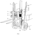
- la figure 1 est une vue en perspective d'un tablier peseur monté sur un chariot élévateur;
- la figure 2 est un schéma synoptique des composants et fonctions du boîtier de raccordement.
In these drawings:
- Figure 1 is a perspective view of a weighing deck mounted on a forklift;
- Figure 2 is a block diagram of the components and functions of the connection box.
Le tablier peseur monobloc (1) représenté aux figures comporte des fourches (2), des bras de liaison (3) reliant lesdites fourches, des bras de liaison (4) reliés de manière coulissante à des chemins de roulement (5) appartenant à deux mâts (6), des capteurs (7), généralement à jauge de contrainte, intercalés entre lesdits bras de liaison (3) et (4), un boîtier de raccordement (8), solidaire du tablier mobile (3,4), interprétant les mesures et transmettant les résultats à un indicateur de poids (9) solidaire du support (10) auquel les mâts (6) sont fixés.
Le boîtier (8) comporte une unité de conversion analogique/numérique (11) multivoies , apte à traiter simultanément les mesures provenant des divers capteurs (7), et un micro-contrôleur (12) apte à effectuer automatiquement les réglages des angles, à configurer le fonctionnement du module, à faire la moyenne des valeurs converties et à stocker les divers paramètres de fonctionnement.
La liaison entre ledit boîtier de raccordement (8) et les mâts (6),s'effectue par émetteur (13)/récepteur (14), à faisceau directif infrarouge, qui transmet, à l'indicateur de poids (9), les informations numériques provenant dudit boîtier (8).
Le boîtier de raccordement (8) peut être utilisé même dans le cas d'un seul capteur.
Le tablier mobile (3,4) peut comporter un tiroir batterie (15) interchangeable apte à alimenter les capteurs (7), le boîtier (8) et l'émetteur infrarouge (13).
L'émetteur (13) est par exemple fixé au bras de liaison (4) et le récepteur (14) à la base du mât (6), dans l'alignement l'un de l'autre.
Le signal donnant la tension de la batterie rechargeable (15) est relié au boîtier de raccordement (8) qui transmet ledit signal numérisé à l'indicateur de poids (9).
Le boîtier comporte en outre, en amont du convertisseur (11), pour chaque capteur (7), un module d'amplification (16) précédé d'un filtre passe-bas passif, ayant une fréquence de coupure de 20 Hz, et suivi d'un filtre actif du deuxième ordre, centré sur 5 Hz.
Le convertisseur (11) comporte en interne un filtre numérique passe-bas à fréquence de coupure programmable.
Le micro-contrôleur (12) est associé :
- à un module (17) de stockage des paramètres du type "EEPROM";
- à un module (18) de configuration du fonctionnement de l'ensemble, comportant un bouton poussoir de prise de mesure des valeurs des capteurs lors du réglage des angles, des interrupteurs aptes à sélectionner le mode de fonctionnement et des "LED" de visualisation associés auxdits interrupteurs;
- à une carte de sortie RS 232 (19).
Le réglage des angles se fait simplement enappliquant successivement 1/3 de la portée maximale sur chacun des 4 angles et en validant, avec le bouton poussoir du module (18), les prises de mesure simultanées des 4 capteurs (grâce au convertisseur A/N multivoies) et leur mémorisation instantanée.
Une fois le tour des angles effectué, le micro-contrôleur (12) calcule automatiquement l'algorithme de réglage (qui prend en compte les transferts de charges) et en stocke les paramètres. Cet algorithme est ensuite appliqué automatiquement à chaque calcul de la moyenne des signaux.
Le microcontrôleur assure le traitement et la mise en forme des mesures.
Il sert à initialiser le convertisseur en programmant notamment sa fréquence de coupure et à récupérer le résultat de la conversion des 4 voies.
- faire la moyenne (cas de plusieurs capteurs) des valeurs converties en tenant compte du réglage des angles;
- envoyer le résultat de la moyenne au format RS 232;
- calculer l'algorithme de réglage des angles avec stockage dans la mémoire "EEPROM";
- configurer le fonctionnement du module;
- surveiller le fonctionnement de la boîte avec envoi des messages d'erreurs éventuels; avec en particulier la surveillance de la tension d'alimentation et des valeurs stockées dans la mémoire.
- mode mesure;
- mode configuration (acquisition du nombre des capteurs);
- mode de réglage semi-automatique des angles (calcul des paramètres de l'algorithme).
Dès que la batterie n'a plus la charge suffisante pour éviter toute erreur de lecture, le boîtier bloque les mesures jusqu'à son remplacement.
La batterie (15) sert à alimenter le module (23) d'alimentation des capteurs et le module (24) d'alimentation de l'électronique (tension de référence à correction ratiomètrique).
La liaison sortie (19) - indicateur (9) peut se faire par cable (25).The one-piece weighbridge (1) shown in the figures includes forks (2), link arms (3) connecting said forks, link arms (4) slidably connected to raceways (5) belonging to two masts (6), sensors (7), generally with strain gauge, interposed between said link arms (3) and (4), a connection box (8), integral with the movable bulkhead (3,4), interpreting the measurements and transmitting the results to a weight indicator (9) integral with the support (10) to which the masts (6) are fixed.
The housing (8) comprises a multi-channel analog / digital conversion unit (11), capable of simultaneously processing the measurements coming from the various sensors (7), and a microcontroller (12) capable of automatically adjusting the angles, at configure the operation of the module, average the converted values and store the various operating parameters.
The connection between said connection box (8) and the masts (6) is effected by transmitter (13) / receiver (14), with an infrared directive beam, which transmits, to the weight indicator (9), the digital information from said housing (8).
The connection box (8) can be used even in the case of a single sensor.
The movable deck (3,4) may include an interchangeable battery drawer (15) capable of supplying the sensors (7), the housing (8) and the infrared transmitter (13).
The transmitter (13) is for example fixed to the link arm (4) and the receiver (14) at the base of the mast (6), in alignment with one another.
The signal giving the voltage of the rechargeable battery (15) is connected to the connection box (8) which transmits said digitized signal to the weight indicator (9).
The housing further comprises, upstream of the converter (11), for each sensor (7), an amplification module (16) preceded by a passive low-pass filter, having a cut-off frequency of 20 Hz, and followed a second order active filter, centered on 5 Hz.
The converter (11) internally comprises a digital low-pass filter with programmable cut-off frequency.
The microcontroller (12) is associated:
- a module (17) for storing parameters of the "EEPROM"type;
- a module (18) for configuring the operation of the assembly, comprising a push button for measuring the values of the sensors when adjusting the angles, switches able to select the operating mode and associated "LEDs" for display to said switches;
- to an RS 232 output card (19).
The adjustment of the angles is done simply by successively applying 1/3 of the maximum range on each of the 4 angles and by validating, with the push button on the module (18), the simultaneous measurements of the 4 sensors (thanks to the A / D converter multichannels) and their instant storage.
Once the tour of the angles has been completed, the microcontroller (12) automatically calculates the adjustment algorithm (which takes charge transfers into account) and stores the parameters. This algorithm is then applied automatically to each calculation of the mean of the signals.
The microcontroller processes and formats the measurements.
It is used to initialize the converter by programming in particular its cut-off frequency and to recover the result of the conversion of the 4 channels.
- averaging (in the case of several sensors) the converted values taking into account the adjustment of the angles;
- send the result of the average in RS 232 format;
- calculate the algorithm for adjusting the angles with storage in the "EEPROM"memory;
- configure the operation of the module;
- monitor the operation of the box with sending of possible error messages; with in particular the monitoring of the supply voltage and the values stored in the memory.
- measurement mode;
- configuration mode (acquisition of the number of sensors);
- semi-automatic angle adjustment mode (calculation of algorithm parameters).
As soon as the battery no longer has sufficient charge to avoid any reading error, the box blocks the measurements until it is replaced.
The battery (15) is used to supply the sensor supply module (23) and the electronics supply module (24) (reference voltage with ratiometric correction).
The output (19) - indicator (9) connection can be made by cable (25).
Bien entendu, l'invention n'est pas limitée aux modes de réalisation décrits et représentés pour lesquels on pourra prévoir d'autres variantes en particulier dans :
- le nombre et le type de capteurs;
- le type de liaison entre le boîtier et l'indicateur;
- les caractéristiques des modules (amplificateurs, convertisseur, micro-contrôleur, module de stockage) entrant dans la composition du boîtier; sans pour celà sortir du cadre de l'invention.
- the number and type of sensors;
- the type of connection between the housing and the indicator;
- the characteristics of the modules (amplifiers, converter, microcontroller, storage module) used in the composition of the box; without thereby departing from the scope of the invention.
Claims (8)
caractérisé en ce que l'unité de conversion analogique/numérique (11) est réalisée au moyen d'un convertisseur multivoies, dont le nombre de voies correspond au nombre de capteurs intercalés entre les bras de liaison (3) et (4), apte à mesurer simultanément et à mémoriser les diverses valeurs de charge données par lesdits capteurs; en ce que le micro-contrôleur effectue automatiquement le réglage des angles, configure le fonctionnement du module, réalise la moyenne des valeurs converties et stocke les divers paramètres de fonctionnement, et en ce que la liaison entre le boîtier de raccordement (8), solidaire du tablier mobile (3,4), et l'indicateur de poids (9), solidaire des mâts fixes (6), s'effectue au moyen d'un émetteur/récepteur(13,14), à faisceau directif infrarouge, qui transmet les informations numériques relatives en particulier aux résultats des mesures de poids.One-piece weighbridge (1) of the kind comprising forks (2), link arms (3) connecting said forks, link arms (4) slidably connected to raceways (5) belonging to two masts ( 6), sensors (7), generally with strain gauge, interposed between said link arms (3) and (4), a connection box (8), integral with the movable bulkhead (3,4), associated with a analog / digital conversion unit (11) and a microcontroller (12) interpreting the measurements and transmitting the results to a weight indicator (9) secured to the support (10) to which the masts (6) are connected;
characterized in that the analog / digital conversion unit (11) is produced by means of a multi-channel converter, the number of channels of which corresponds to the number of sensors interposed between the link arms (3) and (4), suitable simultaneously measuring and storing the various charge values given by said sensors; in that the microcontroller automatically adjusts the angles, configures the operation of the module, averages the converted values and stores the various operating parameters, and in that the connection between the connection box (8), integral of the movable deck (3,4), and the weight indicator (9), integral with the fixed masts (6), is carried out by means of a transmitter / receiver (13,14), with an infrared directive beam, which transmits digital information relating in particular to the results of the weight measurements.
Applications Claiming Priority (2)
| Application Number | Priority Date | Filing Date | Title |
|---|---|---|---|
| FR9605129 | 1996-04-22 | ||
| FR9605129A FR2747778B1 (en) | 1996-04-22 | 1996-04-22 | AUTONOMOUS MONOBLOCK WEIGHING APRON |
Publications (2)
| Publication Number | Publication Date |
|---|---|
| EP0803717A1 true EP0803717A1 (en) | 1997-10-29 |
| EP0803717B1 EP0803717B1 (en) | 2001-11-21 |
Family
ID=9491521
Family Applications (1)
| Application Number | Title | Priority Date | Filing Date |
|---|---|---|---|
| EP19970400896 Expired - Lifetime EP0803717B1 (en) | 1996-04-22 | 1997-04-22 | Autonomous one-piece weigh-table |
Country Status (3)
| Country | Link |
|---|---|
| EP (1) | EP0803717B1 (en) |
| DE (1) | DE69708375T2 (en) |
| FR (1) | FR2747778B1 (en) |
Cited By (4)
| Publication number | Priority date | Publication date | Assignee | Title |
|---|---|---|---|---|
| EP0940659A1 (en) * | 1998-03-05 | 1999-09-08 | Balea S.A. | Method for adjusting the angle of a load receiver and device for carrying out the process |
| EP0971216A3 (en) * | 1998-01-13 | 2000-02-16 | Leon Engineering A.B.E. | Intelligent digital junction box |
| WO2001003990A1 (en) * | 1999-07-12 | 2001-01-18 | Ravas Europe B.V. | Mobile lifting device and weighing device therefor |
| US9932213B2 (en) | 2014-09-15 | 2018-04-03 | Crown Equipment Corporation | Lift truck with optical load sensing structure |
Families Citing this family (2)
| Publication number | Priority date | Publication date | Assignee | Title |
|---|---|---|---|---|
| FR2791049B1 (en) | 1999-03-19 | 2001-06-01 | Sambron | EQUIPMENT CARRIER FOR A LIFTING MACHINE, A MAT OF A LIFTING MACHINE COMPRISING SUCH AN EQUIPMENT CARRIER AND LIFTING MACHINE SUCH AS A FORK TROLLEY PROVIDED WITH SAID MAT |
| DE102021128642A1 (en) | 2021-11-03 | 2023-05-04 | Weidemann GmbH | Construction machine or agricultural machine |
Citations (6)
| Publication number | Priority date | Publication date | Assignee | Title |
|---|---|---|---|---|
| EP0046692A2 (en) * | 1980-08-25 | 1982-03-03 | Weigh-Tronix, Inc. | Fork lift scale |
| US4323132A (en) * | 1980-08-25 | 1982-04-06 | Weigh-Tronix, Inc. | Mounting adapter for a fork lift truck |
| DE3629244A1 (en) * | 1985-08-30 | 1987-03-26 | Carsten Prof Dr Ahrens | Method and device for determining the weight and/or the centre-of-gravity position in space of containers |
| FR2639931A1 (en) * | 1988-12-06 | 1990-06-08 | Aimo Ets | Handling vehicle equipped with a weighing device |
| FR2651880A1 (en) * | 1989-09-11 | 1991-03-15 | Odru Robert | Method and device for weighing a load |
| FR2708585A1 (en) * | 1993-07-30 | 1995-02-10 | Safe | Truck for handling a load |
-
1996
- 1996-04-22 FR FR9605129A patent/FR2747778B1/en not_active Expired - Fee Related
-
1997
- 1997-04-22 EP EP19970400896 patent/EP0803717B1/en not_active Expired - Lifetime
- 1997-04-22 DE DE1997608375 patent/DE69708375T2/en not_active Expired - Fee Related
Patent Citations (6)
| Publication number | Priority date | Publication date | Assignee | Title |
|---|---|---|---|---|
| EP0046692A2 (en) * | 1980-08-25 | 1982-03-03 | Weigh-Tronix, Inc. | Fork lift scale |
| US4323132A (en) * | 1980-08-25 | 1982-04-06 | Weigh-Tronix, Inc. | Mounting adapter for a fork lift truck |
| DE3629244A1 (en) * | 1985-08-30 | 1987-03-26 | Carsten Prof Dr Ahrens | Method and device for determining the weight and/or the centre-of-gravity position in space of containers |
| FR2639931A1 (en) * | 1988-12-06 | 1990-06-08 | Aimo Ets | Handling vehicle equipped with a weighing device |
| FR2651880A1 (en) * | 1989-09-11 | 1991-03-15 | Odru Robert | Method and device for weighing a load |
| FR2708585A1 (en) * | 1993-07-30 | 1995-02-10 | Safe | Truck for handling a load |
Cited By (5)
| Publication number | Priority date | Publication date | Assignee | Title |
|---|---|---|---|---|
| EP0971216A3 (en) * | 1998-01-13 | 2000-02-16 | Leon Engineering A.B.E. | Intelligent digital junction box |
| EP0940659A1 (en) * | 1998-03-05 | 1999-09-08 | Balea S.A. | Method for adjusting the angle of a load receiver and device for carrying out the process |
| WO2001003990A1 (en) * | 1999-07-12 | 2001-01-18 | Ravas Europe B.V. | Mobile lifting device and weighing device therefor |
| US6855894B1 (en) * | 1999-07-12 | 2005-02-15 | Ravas Europe B.V. | Mobile lifting device and weighing device therefor |
| US9932213B2 (en) | 2014-09-15 | 2018-04-03 | Crown Equipment Corporation | Lift truck with optical load sensing structure |
Also Published As
| Publication number | Publication date |
|---|---|
| FR2747778B1 (en) | 1998-07-10 |
| DE69708375D1 (en) | 2002-01-03 |
| DE69708375T2 (en) | 2002-07-18 |
| FR2747778A1 (en) | 1997-10-24 |
| EP0803717B1 (en) | 2001-11-21 |
Similar Documents
| Publication | Publication Date | Title |
|---|---|---|
| EP2875320B1 (en) | Weighing device and method | |
| WO2006061830A3 (en) | Automated monitoring of analog guages | |
| EP0114536B1 (en) | Multi-probe measuring apparatus | |
| EP1107009A1 (en) | Current intensity measuring apparatus in a conductor | |
| EP0007288B1 (en) | Arrangement for measuring the intensity of a force which is transversally exerted on the free end of a flexion beam | |
| EP0803717B1 (en) | Autonomous one-piece weigh-table | |
| FR2613267A1 (en) | TOOL HOLDER WITH TIME OF SERVICE CONTROL | |
| FR2724728A1 (en) | Measuring system for determining force and power applied e.g at bicycle crank | |
| EP2402724A1 (en) | Method for calibrating a weight sensor, weight sensor for implementing said method and electronic weighing appliance | |
| FR2484632A1 (en) | DEVICE FOR MEASURING THE POSITION OF WHEELS | |
| FR2683313A1 (en) | DEVICE FOR MEASURING PARAMETERS, IN PARTICULAR PARAMETERS RELATING TO AIRCRAFT WHEELS OR VEHICLES. | |
| EP1769827A1 (en) | Safety binding | |
| US7783446B2 (en) | Measuring system comprising variably sensitive outputs | |
| EP0162990B1 (en) | Monoway measuring head and telemetry installation including such a head | |
| FR2938911A1 (en) | Measurement system for dynamic measurement of load raised by lifting machine, has control and processing unit comparing data provided by current sensor to calibration data and generating data relative to weight of load based on comparison | |
| EP1476725A2 (en) | Recording module with a universal input for measurement of physical parameters | |
| EP0819921A1 (en) | Real time weighing device | |
| FR2478412A1 (en) | Automatic impedance appts. for telephone network - momentarily samples impedance magnitude and stores that data to provide stable information to adaptation system | |
| CA1241436A (en) | Antenna orienting device | |
| FR2737304A1 (en) | Zero reset on current measuring equipment - using analogue to digital converters to measure output discrepancy and calculator to generate correction to amplifier | |
| WO1999042795A1 (en) | Portable electronic weigh box | |
| FR2684761A1 (en) | Method and device for measuring the axle load of a vehicle | |
| FR2627766A1 (en) | Fork-shaped palette transport appts. - has digital indicator, with one of five gauges fitted to cross-piece which joins ends of fork together | |
| FR3129131A1 (en) | Connected bike pedal | |
| FR3037206A1 (en) | VIDEO RECORDING SYSTEM AND METHOD FOR FISHING PART |
Legal Events
| Date | Code | Title | Description |
|---|---|---|---|
| PUAI | Public reference made under article 153(3) epc to a published international application that has entered the european phase |
Free format text: ORIGINAL CODE: 0009012 |
|
| AK | Designated contracting states |
Kind code of ref document: A1 Designated state(s): BE DE ES FR GB IT NL |
|
| 17P | Request for examination filed |
Effective date: 19980209 |
|
| 17Q | First examination report despatched |
Effective date: 20000524 |
|
| GRAG | Despatch of communication of intention to grant |
Free format text: ORIGINAL CODE: EPIDOS AGRA |
|
| GRAG | Despatch of communication of intention to grant |
Free format text: ORIGINAL CODE: EPIDOS AGRA |
|
| GRAH | Despatch of communication of intention to grant a patent |
Free format text: ORIGINAL CODE: EPIDOS IGRA |
|
| GRAH | Despatch of communication of intention to grant a patent |
Free format text: ORIGINAL CODE: EPIDOS IGRA |
|
| GRAA | (expected) grant |
Free format text: ORIGINAL CODE: 0009210 |
|
| AK | Designated contracting states |
Kind code of ref document: B1 Designated state(s): BE DE ES FR GB IT NL |
|
| REG | Reference to a national code |
Ref country code: GB Ref legal event code: IF02 |
|
| REF | Corresponds to: |
Ref document number: 69708375 Country of ref document: DE Date of ref document: 20020103 |
|
| PGFP | Annual fee paid to national office [announced via postgrant information from national office to epo] |
Ref country code: GB Payment date: 20020211 Year of fee payment: 6 |
|
| GBT | Gb: translation of ep patent filed (gb section 77(6)(a)/1977) |
Effective date: 20020216 |
|
| PG25 | Lapsed in a contracting state [announced via postgrant information from national office to epo] |
Ref country code: BE Free format text: LAPSE BECAUSE OF NON-PAYMENT OF DUE FEES Effective date: 20020430 |
|
| PG25 | Lapsed in a contracting state [announced via postgrant information from national office to epo] |
Ref country code: ES Free format text: LAPSE BECAUSE OF FAILURE TO SUBMIT A TRANSLATION OF THE DESCRIPTION OR TO PAY THE FEE WITHIN THE PRESCRIBED TIME-LIMIT Effective date: 20020530 |
|
| PLBE | No opposition filed within time limit |
Free format text: ORIGINAL CODE: 0009261 |
|
| STAA | Information on the status of an ep patent application or granted ep patent |
Free format text: STATUS: NO OPPOSITION FILED WITHIN TIME LIMIT |
|
| PG25 | Lapsed in a contracting state [announced via postgrant information from national office to epo] |
Ref country code: NL Free format text: LAPSE BECAUSE OF NON-PAYMENT OF DUE FEES Effective date: 20021101 Ref country code: DE Free format text: LAPSE BECAUSE OF NON-PAYMENT OF DUE FEES Effective date: 20021101 |
|
| 26N | No opposition filed | ||
| NLV4 | Nl: lapsed or anulled due to non-payment of the annual fee |
Effective date: 20021101 |
|
| PG25 | Lapsed in a contracting state [announced via postgrant information from national office to epo] |
Ref country code: GB Free format text: LAPSE BECAUSE OF NON-PAYMENT OF DUE FEES Effective date: 20030422 |
|
| GBPC | Gb: european patent ceased through non-payment of renewal fee |
Effective date: 20030422 |
|
| PG25 | Lapsed in a contracting state [announced via postgrant information from national office to epo] |
Ref country code: IT Free format text: LAPSE BECAUSE OF NON-PAYMENT OF DUE FEES;WARNING: LAPSES OF ITALIAN PATENTS WITH EFFECTIVE DATE BEFORE 2007 MAY HAVE OCCURRED AT ANY TIME BEFORE 2007. THE CORRECT EFFECTIVE DATE MAY BE DIFFERENT FROM THE ONE RECORDED. Effective date: 20050422 |
|
| REG | Reference to a national code |
Ref country code: FR Ref legal event code: PLFP Year of fee payment: 20 |
|
| PGFP | Annual fee paid to national office [announced via postgrant information from national office to epo] |
Ref country code: FR Payment date: 20160428 Year of fee payment: 20 |