EP0803680A2 - Circuit et procédé pour surveiller un appareil chauffé au fuel - Google Patents
Circuit et procédé pour surveiller un appareil chauffé au fuel Download PDFInfo
- Publication number
- EP0803680A2 EP0803680A2 EP97105891A EP97105891A EP0803680A2 EP 0803680 A2 EP0803680 A2 EP 0803680A2 EP 97105891 A EP97105891 A EP 97105891A EP 97105891 A EP97105891 A EP 97105891A EP 0803680 A2 EP0803680 A2 EP 0803680A2
- Authority
- EP
- European Patent Office
- Prior art keywords
- signal
- circuit arrangement
- safety
- counting
- arrangement according
- Prior art date
- Legal status (The legal status is an assumption and is not a legal conclusion. Google has not performed a legal analysis and makes no representation as to the accuracy of the status listed.)
- Granted
Links
- 238000012544 monitoring process Methods 0.000 title claims abstract description 6
- 238000000034 method Methods 0.000 title claims 2
- 238000012360 testing method Methods 0.000 claims abstract description 22
- 239000000446 fuel Substances 0.000 claims abstract description 4
- 239000004065 semiconductor Substances 0.000 claims description 7
- 238000012806 monitoring device Methods 0.000 claims description 6
- 230000000737 periodic effect Effects 0.000 claims description 2
- 230000006870 function Effects 0.000 description 4
- 238000010586 diagram Methods 0.000 description 3
- 230000015654 memory Effects 0.000 description 3
- 230000003111 delayed effect Effects 0.000 description 2
- 230000001419 dependent effect Effects 0.000 description 1
- 238000010438 heat treatment Methods 0.000 description 1
- 230000004044 response Effects 0.000 description 1
- 230000001629 suppression Effects 0.000 description 1
Images
Classifications
-
- F—MECHANICAL ENGINEERING; LIGHTING; HEATING; WEAPONS; BLASTING
- F23—COMBUSTION APPARATUS; COMBUSTION PROCESSES
- F23N—REGULATING OR CONTROLLING COMBUSTION
- F23N5/00—Systems for controlling combustion
- F23N5/24—Preventing development of abnormal or undesired conditions, i.e. safety arrangements
- F23N5/242—Preventing development of abnormal or undesired conditions, i.e. safety arrangements using electronic means
-
- F—MECHANICAL ENGINEERING; LIGHTING; HEATING; WEAPONS; BLASTING
- F23—COMBUSTION APPARATUS; COMBUSTION PROCESSES
- F23N—REGULATING OR CONTROLLING COMBUSTION
- F23N2227/00—Ignition or checking
- F23N2227/12—Burner simulation or checking
-
- F—MECHANICAL ENGINEERING; LIGHTING; HEATING; WEAPONS; BLASTING
- F23—COMBUSTION APPARATUS; COMBUSTION PROCESSES
- F23N—REGULATING OR CONTROLLING COMBUSTION
- F23N2231/00—Fail safe
- F23N2231/30—Representation of working time
Definitions
- the invention relates to a circuit arrangement for monitoring a fuel-heated device with a control device which is supplied with at least one safety-relevant input signal, and with a safety device which has a switching device for switching off at least one valve in a fuel supply, the switch-off depending on the safety-relevant input signal and / or a test signal from the control device.
- Such a circuit arrangement is known from DE 41 11 947 A1.
- the device is switched off in the event of a detected fault by means of a safety circuit, which has a thermal bimetal switch. This enables a delayed switching of the valve, the delayed switching being necessary in particular in the ignition phase.
- thermal bimetal switch has a disadvantage of in particular its high price and its sluggish response.
- the switch can only be reset after a longer period of time after repeated switching due to the high temperature rise.
- DE 43 42 903 A1 Another device for monitoring at least one safety-relevant function of a fuel-heated device is known from DE 43 42 903 A1.
- two microprocessors are provided which determine the states of the device and / or errors and each store them in a memory. However, the device is only switched off when a comparison shows that the states or errors stored in both memories match.
- the circuit arrangement according to the invention with the features of claim 1 has the advantage, that a simple circuit device, preferably a bistable relay or a semiconductor switch, can be used by using a counting device.
- the necessary delay function, which has been achieved so far by heating the bimetal switch, is provided by the counting device, which can be implemented cost-effectively.
- delay times can be set much more flexibly, preferably even different delay times being possible with different input signal constellations.
- a logic device to which the safety-relevant input signal, the test signal originating from the control device and a clock signal generated by a clock generator are fed. This makes it possible in a circuit-technically simple manner to route the clock signal to the downstream counting device as a function of the other two signals. It is very particularly advantageous, depending on the constellation of the input signal and the test signal, to supply the counting device with a clock signal for incrementing or a clock signal for decrementing.
- the two clock signals preferably differ with regard to their clock frequency.
- a dividing device is provided between the linking device and the clock generator, which divides the clock frequency down by a divider, which is preferably freely selectable.
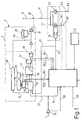
- Figure 1 shows a circuit arrangement 1, which is part of a gas burner control, for example. It comprises a control device 3, a safety device 5 outlined in dashed lines and two solenoid valves 7.1 and 7.2 which are not connected to one shown lead to a burner gas supply line act.
- the two solenoid valves 7 are connected to the positive pole of a voltage supply via a common supply line 9 and to ground via separate lines 11.1 and 11.2.
- the supply line 9 can be interrupted via a switch 13 and a switch 15 arranged in series with it.
- a switch 17.1 and 17.2 is also arranged in each of the two supply lines 11.1, 11.2.
- the voltage drop across the two solenoid valves 7 is passed via an amplifier 19 as a solenoid valve voltage signal via a line 21 to the control device 3.
- a line 23 feeds this signal to the safety device 5 as one of several safety-relevant input signals.
- a flame monitoring device supplies an ionization signal which is fed to the control device 3 via a line 25 and to the safety device 5 via a line 27. Via a line 29, the control device 3 can block the signal supplied by the flame monitoring device in an amplifier 31 for testing purposes.
- control device 3 receives a heat request via a line 33, which leads to an ignition of the burner.
- the safety device 5 is composed of several functional units.
- the two safety-relevant input signals supplied via lines 23 and 27 are processed in a linkage device 37 together with a test signal transmitted via line 35. Depending on this processing, either a first clock signal is fed to a decrement input 39 or a second clock signal is fed to an increment input 41 of an up / down counter 43.
- the first clock signal is fed via a line 45 and the second clock signal via a line 47 to the linking device 37.
- the clock signals themselves are generated by a clock generator 49, the clock frequency for both clock signals being reduced by a pre-divider 51.
- the clock frequency of the second clock signal can be varied by means of a switching device 53. Switching between four different frequencies in the present case is accomplished by two control lines 55.1 and 55.2 through the control device 3.
- the first three of a total of four outputs Q0, Q1 and Q2 of the counter 43 in the exemplary embodiment are fed to an AND gate 57, while the fourth output signal Q3 is fed to an AND gate 59.
- This AND gate 59 receives the output signal of the AND gate 57 as a second input signal.
- the output signal of the second AND gate 59 is then used to control a bistable relay 61 which actuates the aforementioned switch 13. Since it is a bistable relay, an unlocking device 63 is provided for switching back, which switches the relay back into a state in which the switch 13 is closed by actuating a button 65.
- the output signal of the first AND gate 57 is fed to the control device 3 via a line 67.1 and the fourth output signal Q3 of the counter 43 is fed via a line 67.2.
- the two double arrows at the ends of these two lines are intended to indicate that the control device 3 can also actively control the AND gate 59 for test purposes.
- the output signal of the AND gate 59 is fed to a monitoring device 69, also referred to below as a watchdog.
- a monitoring device 69 also referred to below as a watchdog.
- Such watchdogs are generally known and check periodic events within a predetermined time window, for example the periodicity of trigger pulses.
- the time window mentioned is predetermined by the clock generator 49 and the pre-divider 51.
- the test signal is generated and passed on to line 35 to linkage device 37.
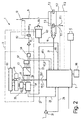
- the circuit arrangement shown in FIG. 2 essentially corresponds to the first exemplary embodiment, which is why a detailed description is omitted again.
- relay 81 which is not designed as a bistable, but as a monostable relay. This makes it necessary to design the switch 13 as a changeover switch, which either connects the supply line 9 or a line 83 leading to the relay 81 to the positive pole of the supply voltage.
- unlocking device 63 passes a signal via a line 85 to the control device 3.
- control device 3 is assigned a memory chip 86, preferably an EEPROM.
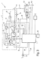
- circuit arrangement shown in FIG. 3 essentially corresponds to that already described with reference to FIG. 1, so that a further detailed description is dispensed with.
- the switch 13 which in the present case is designed as a highside semiconductor switch.
- the voltage is tapped from the supply line 9 and by means of an inverter 91 fed to the clock generator 49 via a line 93 and a filter 95.
- the signal is processed in the clock generator 49 so that an open switch 13 leads to an interruption of the clock generation.
- the unlocking device 63 is designed only as a button 65, which supplies a reset signal to the counter 43 via a line 97.
- the control device 3 is also supplied with an unlocking signal via a line 99.
- the trigger signal for the watchdog 69 is fed directly from the control device 3 via a line 101.
- the circuit arrangement 1 has two independently working ways of switching off the burner.
- the solenoid valves 7 can thus be closed either by the control device 3 via the switches 17 or together by the safety device 5 via the switch 13.
- a fault occurs in normal operation, for example, when the solenoid valves are open and thus supply a corresponding signal via line 23 to the safety device 5 and the flame monitoring device indicates that there is no flame, with a corresponding signal via line 27 to the safety device 5 is transmitted.
- the two signals are then linked in the combination device 37 such that a clock signal is fed to the counter 43. This counts up, the output signals Q0 to Q3 being linked in such a way that the relay 61 is activated after a certain delay time and the switch 13 is thus opened.
- the solenoid valves 7 are closed and the gas supply is interrupted.
- the counter 43 is provided, which initially counts up after the valves 7 open and does not yet trigger the relay 61.
- the switch 13 is only opened after the counter reading determined by the AND gates 57, 59 has been reached.
- the clock generator 49 and the interconnection of the outputs of the counter 43 are preferably designed such that there is a delay time of approximately 10 seconds. If the flame monitoring device detects a flame within this time period, the corresponding signal is processed by the linking device 37 and the supply of the clock signal to the counter 43 is interrupted. Rather, the counter is decremented in this state until it has reached the smallest value.
- the safety device 5 also monitors the control device 3.
- the watchdog 69 which receives a trigger signal periodically generated by the control device 3. This trigger signal is transmitted via lines 67 and AND gate 59. If the trigger pulse now falls within the time window generated by the watchdog 69, the control device 3 works properly. However, if a deviation can be determined, a test signal is transmitted to the linkage device 37 via the line 35. This then leads to the counting up of the counter 43 and to the triggering of the relay 61 if the counter is not stopped again within the delay time.
- the trigger pulse generated by the control device 3 is so short that the relay 61 is not affected by it.
- the choice of two clock frequencies gives the possibility of incrementing the counter 43 faster in the presence of a signal from the watchdog 69 than in the former case, so that the delay time in the event of a fault in the control device 3 is, for example, only 2.5 seconds.
- the functionality of the safety device 5 is also checked by the control device 3.
- the control device 3 To test the watchdog 69, the control device 3 generates a trigger pulse which does not match the time window, which leads to the generation of a test signal and the counting up of the counter 43.
- the counter 43 is then functional, when the control device 3 first detects an output signal at the AND gate 57 via the line 67.1 and shortly thereafter a signal at the output Q3 of the counter 43 via the line 67.2.
- the test is interrupted immediately when the signal at output Q3 is detected.
- a further test of watchdog 69 is carried out in the same way, but not a trigger pulse that is incorrect in time, but rather no trigger pulse is generated. In this case, too, the operability is confirmed by the signals detected in succession via lines 67.1 and 67.2.
- a further test of the safety device 5 takes place in that the ionization signal is suppressed by the control device 3 via the line 29. With perfect functionality, this also has the consequence that the counter 43 is incremented and signals appearing in quick succession can be detected via the line 67.1 and the line 67.2. In order to avoid triggering the relay, the suppression of the ionization signal is canceled immediately when the output signal Q3 of the counter 43 is detected via the line 67.2.
- the shutdown by the safety device 5 takes place, for example, only in the case of safety errors of class C, with the control device 3 bringing about a shutdown in the case of all other safety errors via the switches 17.
- the control device 3 bringing about a shutdown in the case of all other safety errors via the switches 17.
- the bistable relay 61 according to FIG. 1 is unlocked via the unlocking device 63 and the button 65, through which a current flowing in the opposite direction is sent through the relay, so that the switch 13 switches back into the closed position.
- the unlocking device 63 By means of a corresponding design of the unlocking device 63, it is possible to enable unlocking only after a certain time, for example two seconds. In this case, a simple implementation would be an RC switching element.
- the switches 17 are also unlocked via a button (not shown) or a data line which transmits the command to the control device 3 to close the switches 17.
- the watchdog 69 and the digital logic part of the circuit arrangement 1 can preferably be implemented discretely with a few CMOS logic ICs.
- CMOS logic ICs CMOS logic ICs
- programmable logic modules semiconductor-oxide-semiconductors
- a compact automatic burner control unit can be implemented together with a microcomputer for the control device 3 and corresponding software.
Landscapes
- Engineering & Computer Science (AREA)
- Chemical & Material Sciences (AREA)
- Combustion & Propulsion (AREA)
- Mechanical Engineering (AREA)
- General Engineering & Computer Science (AREA)
- Regulation And Control Of Combustion (AREA)
Applications Claiming Priority (2)
| Application Number | Priority Date | Filing Date | Title |
|---|---|---|---|
| DE19616065 | 1996-04-23 | ||
| DE19616065A DE19616065A1 (de) | 1996-04-23 | 1996-04-23 | Schaltungsanordnung zum Überwachen eines brennstoffbeheizten Gerätes |
Publications (3)
| Publication Number | Publication Date |
|---|---|
| EP0803680A2 true EP0803680A2 (fr) | 1997-10-29 |
| EP0803680A3 EP0803680A3 (fr) | 1999-07-21 |
| EP0803680B1 EP0803680B1 (fr) | 2003-07-09 |
Family
ID=7792132
Family Applications (1)
| Application Number | Title | Priority Date | Filing Date |
|---|---|---|---|
| EP97105891A Expired - Lifetime EP0803680B1 (fr) | 1996-04-23 | 1997-04-10 | Circuit et procédé pour surveiller un appareil chauffé au fuel |
Country Status (2)
| Country | Link |
|---|---|
| EP (1) | EP0803680B1 (fr) |
| DE (2) | DE19616065A1 (fr) |
Cited By (6)
| Publication number | Priority date | Publication date | Assignee | Title |
|---|---|---|---|---|
| DE19825846A1 (de) * | 1998-06-10 | 1999-12-16 | Agt Gas Technology Gmbh | Vorrichtung zum Sichern einer Gasbrennstelle |
| EP1070919A3 (fr) * | 1999-07-23 | 2002-12-18 | FAGOR, S.Coop | Circuit de commande pour brûleurs à gaz |
| EP1199519A3 (fr) * | 2000-10-19 | 2003-11-19 | RB Controls Co., Ltd. | Dispositif de commande de combustion |
| EP1164332A3 (fr) * | 2000-06-16 | 2004-04-07 | Siemens Building Technologies AG | Circuit d'entrée pour un brûleur |
| EP1571395A1 (fr) * | 2004-03-02 | 2005-09-07 | Riello S.p.a. | Dispositif de contrôle de flamme de brûleur |
| EP2295863A3 (fr) * | 2009-08-06 | 2014-06-11 | Robert Bosch GmbH | Système de combustion, automate de chauffage au gaz ainsi que dispositif et procédé d'arrêt d'une amenée de combustible correspondant |
Family Cites Families (5)
| Publication number | Priority date | Publication date | Assignee | Title |
|---|---|---|---|---|
| DE2247918C3 (de) * | 1972-09-29 | 1979-03-22 | Otto Dold, Temperaturmess- Und Regelgeraete, 7012 Schmiden | Sicherheitsschaltung fur Feuerungsautomaten in Gas- und ölfeuerungsanlagen |
| US4695246A (en) * | 1984-08-30 | 1987-09-22 | Lennox Industries, Inc. | Ignition control system for a gas appliance |
| EP0315053B1 (fr) * | 1987-11-06 | 1994-02-09 | Joh. Vaillant GmbH u. Co. | Automate de brûleur |
| CH681039A5 (fr) * | 1990-03-23 | 1992-12-31 | Landis & Gyr Betriebs Ag | |
| DE4111947A1 (de) * | 1991-04-12 | 1992-10-15 | Bosch Gmbh Robert | Schaltungsanordnung und verfahren zum ueberwachen eines brennstoffbeheizten geraetes |
-
1996
- 1996-04-23 DE DE19616065A patent/DE19616065A1/de not_active Ceased
-
1997
- 1997-04-10 DE DE59710396T patent/DE59710396D1/de not_active Expired - Lifetime
- 1997-04-10 EP EP97105891A patent/EP0803680B1/fr not_active Expired - Lifetime
Cited By (9)
| Publication number | Priority date | Publication date | Assignee | Title |
|---|---|---|---|---|
| DE19825846A1 (de) * | 1998-06-10 | 1999-12-16 | Agt Gas Technology Gmbh | Vorrichtung zum Sichern einer Gasbrennstelle |
| US6322352B1 (en) | 1998-06-10 | 2001-11-27 | Isphording Germany Gmbh | Gas burner system |
| EP1070919A3 (fr) * | 1999-07-23 | 2002-12-18 | FAGOR, S.Coop | Circuit de commande pour brûleurs à gaz |
| EP1164332A3 (fr) * | 2000-06-16 | 2004-04-07 | Siemens Building Technologies AG | Circuit d'entrée pour un brûleur |
| EP1199519A3 (fr) * | 2000-10-19 | 2003-11-19 | RB Controls Co., Ltd. | Dispositif de commande de combustion |
| EP1571395A1 (fr) * | 2004-03-02 | 2005-09-07 | Riello S.p.a. | Dispositif de contrôle de flamme de brûleur |
| EP2295863A3 (fr) * | 2009-08-06 | 2014-06-11 | Robert Bosch GmbH | Système de combustion, automate de chauffage au gaz ainsi que dispositif et procédé d'arrêt d'une amenée de combustible correspondant |
| EP2295863B1 (fr) | 2009-08-06 | 2019-05-01 | Robert Bosch GmbH | Système de combustion, automate de chauffage au gaz ainsi que dispositif et procédé d'arrêt d'une amenée de combustible correspondant |
| DE102009036423C5 (de) | 2009-08-06 | 2023-03-02 | Robert Bosch Gmbh | Verfahren und Vorrichtung zur Unterbrechung einer Brennstoffzufuhr sowie deren Verwendung |
Also Published As
| Publication number | Publication date |
|---|---|
| EP0803680A3 (fr) | 1999-07-21 |
| DE19616065A1 (de) | 1997-11-06 |
| EP0803680B1 (fr) | 2003-07-09 |
| DE59710396D1 (de) | 2003-08-14 |
Similar Documents
| Publication | Publication Date | Title |
|---|---|---|
| EP0185667B1 (fr) | Remise a l'etat initial d'un microprocesseur | |
| DE3041521C2 (fr) | ||
| DE3880772T2 (de) | Flammendetektorsignal-verarbeitungssystem. | |
| DE4210216C3 (de) | Überwachungsschaltung für computergesteuerte Sicherheitsgeräte | |
| DE4012109A1 (de) | Vorrichtung zur funktionsueberwachung eines elektrischen verbrauchers, seiner ansteuerung und der dazugehoerigen verbindungen | |
| EP1869687B1 (fr) | Dispositif de coupure de securite servant a deconnecter un recepteur electrique de maniere sure | |
| DE60022276T2 (de) | Steuerschaltung für Gasbrenner | |
| DE2701614A1 (de) | Anzeigesystem | |
| EP0803680B1 (fr) | Circuit et procédé pour surveiller un appareil chauffé au fuel | |
| DE1815637A1 (de) | Anordnung zur UEberpruefung einer auf bestimmte Umgebungsbedingungen ansprechenden Einrichtungen bzw. eines ihr zugeordneten Schaltkreises | |
| DE3101747C2 (fr) | ||
| DE2651314B1 (de) | Sicherheits-Ausgabeschaltung fuer eine Binaersignale abgebende Datenverarbeitungsanlage | |
| EP0996060A2 (fr) | Système à processeur unique | |
| DE2630234A1 (de) | Schutzsystem mit pruefmoeglichkeit | |
| DE2222258C2 (de) | Steuerschaltung für eine Brenneranlage. Anal: Landis & Gyr AG, Zug (Schweiz) | |
| EP0660043A1 (fr) | Dispositif de commande pour commander des appareils de commutation selon un programme de temps | |
| EP0660044B1 (fr) | Dispositif de commande pour commander des appareils de commutation | |
| EP0508081B1 (fr) | Circuit et procédé pour surveiller un appareil chauffé au combustible | |
| DE4038925C2 (fr) | ||
| DE4403156A1 (de) | Vorrichtung zur Ansteuerung eines Verbrauchers | |
| DE60216763T2 (de) | Sicherheitseinrichtung für eine feurerungsanlage mit einer verzögerungszeit durch eine elektronische schaltung | |
| EP0730349B1 (fr) | Circuit à enclencher et déclencher une charge électrique | |
| DE3739227C2 (fr) | ||
| DE102005002720B4 (de) | Sicherheitsverfahren für ein Insassenschutzsystem | |
| DE3410257C2 (fr) |
Legal Events
| Date | Code | Title | Description |
|---|---|---|---|
| PUAI | Public reference made under article 153(3) epc to a published international application that has entered the european phase |
Free format text: ORIGINAL CODE: 0009012 |
|
| AK | Designated contracting states |
Kind code of ref document: A2 Designated state(s): DE ES FR GB IT NL |
|
| PUAL | Search report despatched |
Free format text: ORIGINAL CODE: 0009013 |
|
| AK | Designated contracting states |
Kind code of ref document: A3 Designated state(s): DE ES FR GB IT NL |
|
| 17P | Request for examination filed |
Effective date: 20000121 |
|
| 17Q | First examination report despatched |
Effective date: 20011221 |
|
| GRAH | Despatch of communication of intention to grant a patent |
Free format text: ORIGINAL CODE: EPIDOS IGRA |
|
| GRAH | Despatch of communication of intention to grant a patent |
Free format text: ORIGINAL CODE: EPIDOS IGRA |
|
| GRAA | (expected) grant |
Free format text: ORIGINAL CODE: 0009210 |
|
| AK | Designated contracting states |
Designated state(s): DE ES FR GB IT NL |
|
| PG25 | Lapsed in a contracting state [announced via postgrant information from national office to epo] |
Ref country code: NL Free format text: LAPSE BECAUSE OF FAILURE TO SUBMIT A TRANSLATION OF THE DESCRIPTION OR TO PAY THE FEE WITHIN THE PRESCRIBED TIME-LIMIT Effective date: 20030709 Ref country code: IT Free format text: LAPSE BECAUSE OF FAILURE TO SUBMIT A TRANSLATION OF THE DESCRIPTION OR TO PAY THE FEE WITHIN THE PRESCRIBED TIME-LIMIT;WARNING: LAPSES OF ITALIAN PATENTS WITH EFFECTIVE DATE BEFORE 2007 MAY HAVE OCCURRED AT ANY TIME BEFORE 2007. THE CORRECT EFFECTIVE DATE MAY BE DIFFERENT FROM THE ONE RECORDED. Effective date: 20030709 |
|
| REG | Reference to a national code |
Ref country code: GB Ref legal event code: FG4D Free format text: NOT ENGLISH |
|
| REF | Corresponds to: |
Ref document number: 59710396 Country of ref document: DE Date of ref document: 20030814 Kind code of ref document: P |
|
| PG25 | Lapsed in a contracting state [announced via postgrant information from national office to epo] |
Ref country code: ES Free format text: LAPSE BECAUSE OF FAILURE TO SUBMIT A TRANSLATION OF THE DESCRIPTION OR TO PAY THE FEE WITHIN THE PRESCRIBED TIME-LIMIT Effective date: 20031020 |
|
| GBT | Gb: translation of ep patent filed (gb section 77(6)(a)/1977) |
Effective date: 20031029 |
|
| NLV1 | Nl: lapsed or annulled due to failure to fulfill the requirements of art. 29p and 29m of the patents act | ||
| ET | Fr: translation filed | ||
| PLBE | No opposition filed within time limit |
Free format text: ORIGINAL CODE: 0009261 |
|
| STAA | Information on the status of an ep patent application or granted ep patent |
Free format text: STATUS: NO OPPOSITION FILED WITHIN TIME LIMIT |
|
| 26N | No opposition filed |
Effective date: 20040414 |
|
| REG | Reference to a national code |
Ref country code: DE Ref legal event code: R084 Ref document number: 59710396 Country of ref document: DE Effective date: 20121205 |
|
| REG | Reference to a national code |
Ref country code: FR Ref legal event code: PLFP Year of fee payment: 20 |
|
| PGFP | Annual fee paid to national office [announced via postgrant information from national office to epo] |
Ref country code: GB Payment date: 20160422 Year of fee payment: 20 |
|
| PGFP | Annual fee paid to national office [announced via postgrant information from national office to epo] |
Ref country code: FR Payment date: 20160422 Year of fee payment: 20 |
|
| PGFP | Annual fee paid to national office [announced via postgrant information from national office to epo] |
Ref country code: DE Payment date: 20160628 Year of fee payment: 20 |
|
| REG | Reference to a national code |
Ref country code: DE Ref legal event code: R071 Ref document number: 59710396 Country of ref document: DE |
|
| REG | Reference to a national code |
Ref country code: GB Ref legal event code: PE20 Expiry date: 20170409 |
|
| PG25 | Lapsed in a contracting state [announced via postgrant information from national office to epo] |
Ref country code: GB Free format text: LAPSE BECAUSE OF EXPIRATION OF PROTECTION Effective date: 20170409 |