EP0803608A1 - Méthode et appareil pour la saturation sous pression d'un substrat - Google Patents
Méthode et appareil pour la saturation sous pression d'un substrat Download PDFInfo
- Publication number
- EP0803608A1 EP0803608A1 EP97302678A EP97302678A EP0803608A1 EP 0803608 A1 EP0803608 A1 EP 0803608A1 EP 97302678 A EP97302678 A EP 97302678A EP 97302678 A EP97302678 A EP 97302678A EP 0803608 A1 EP0803608 A1 EP 0803608A1
- Authority
- EP
- European Patent Office
- Prior art keywords
- substrate
- chamber
- mandrel
- saturant
- saturator
- Prior art date
- Legal status (The legal status is an assumption and is not a legal conclusion. Google has not performed a legal analysis and makes no representation as to the accuracy of the status listed.)
- Withdrawn
Links
Images
Classifications
-
- D—TEXTILES; PAPER
- D06—TREATMENT OF TEXTILES OR THE LIKE; LAUNDERING; FLEXIBLE MATERIALS NOT OTHERWISE PROVIDED FOR
- D06B—TREATING TEXTILE MATERIALS USING LIQUIDS, GASES OR VAPOURS
- D06B3/00—Passing of textile materials through liquids, gases or vapours to effect treatment, e.g. washing, dyeing, bleaching, sizing, impregnating
- D06B3/10—Passing of textile materials through liquids, gases or vapours to effect treatment, e.g. washing, dyeing, bleaching, sizing, impregnating of fabrics
- D06B3/20—Passing of textile materials through liquids, gases or vapours to effect treatment, e.g. washing, dyeing, bleaching, sizing, impregnating of fabrics with means to improve the circulation of the treating material on the surface of the fabric
- D06B3/201—Passing of textile materials through liquids, gases or vapours to effect treatment, e.g. washing, dyeing, bleaching, sizing, impregnating of fabrics with means to improve the circulation of the treating material on the surface of the fabric the treating material being forced through the textile material
-
- D—TEXTILES; PAPER
- D21—PAPER-MAKING; PRODUCTION OF CELLULOSE
- D21H—PULP COMPOSITIONS; PREPARATION THEREOF NOT COVERED BY SUBCLASSES D21C OR D21D; IMPREGNATING OR COATING OF PAPER; TREATMENT OF FINISHED PAPER NOT COVERED BY CLASS B31 OR SUBCLASS D21G; PAPER NOT OTHERWISE PROVIDED FOR
- D21H23/00—Processes or apparatus for adding material to the pulp or to the paper
- D21H23/02—Processes or apparatus for adding material to the pulp or to the paper characterised by the manner in which substances are added
- D21H23/22—Addition to the formed paper
- D21H23/32—Addition to the formed paper by contacting paper with an excess of material, e.g. from a reservoir or in a manner necessitating removal of applied excess material from the paper
- D21H23/42—Paper being at least partly surrounded by the material on both sides
Definitions
- This invention relates to an improved method and apparatus for pressure saturation of kraft paper with a resin. More particularly, this invention relates to an improvement in the method and apparatus for pressure saturation of a substrate as taught in U.S. Patent No. 4,588,616, published May 13, 1986.
- a porous substrate material such as paper
- a substrate such as kraft paper
- phenolic resin which is a thermosetting resin
- phenolic resin which is a thermosetting resin
- the use of inexpensive precursors, such as paper and the chemical additives to form such products, provides a significant cost or performance advantage over the use of more expensive materials, such as plastic, wood, or metal.
- the advantages gained from the relative accessibility and low expense of the raw materials, however, are diminished by the relative inefficiency and expense of the impregnation apparatus and process employed in their manufacture.
- the process itself involves subjecting a substrate to a normally heated saturant solution to coat the fibers of the substrate with the saturant, and/or to replace the air contained in the interstices of the substrate with the saturant material.
- the carrier which may be water or another appropriate medium, for example, methanol, then evaporates, leaving the fibers encapsulated by the saturant material.
- the composition and thickness of the material are important.
- the saturant solution the composition, temperature, viscosity, and relative pressure are important.
- the design of the saturating apparatus and the speed at which the process is carried out are important.
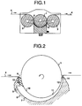
- FIG. 1 representative of the patented Menser saturator (and applicable to the improvement herein) there is shown a central mandrel 1 interposed between separate conveying means, such as side rollers 2 and 3 , the rollers and the mandrel being rotatably mounted at each end thereof.
- the rollers 2 and 3 function as conveyors and, in operation, the substrate 4 , or web, passes over roller 2 , under the mandrel 1 , and over roller 3 , as indicated by the arrows in FIG. 1.
- a suitable driving system such as chain drive 5 , shown in phantom in FIG. 1, for example, is used to drive the rollers and the mandrel during operation.
- the mandrel 1 is mounted over a block member, such as a saddle block 6 , which extends the length of the mandrel l and is adjustable both vertically and transversely.
- the upper surface of the saddle block 6 is sloping and arcuate, or concave, with a diameter greater than that of the mandrel 1 to allow the mandrel 1 to be received therein, and is graduated from a relatively deep portion to a relatively shallow portion.
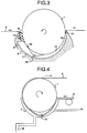
- FIG. 2 which is representative only of the patented Menser apparatus, shows a plenum-like cavity, or chamber, 7 to be thus formed between the mandrel 16 and the saddle block 6 for receiving the saturant solution.
- the saturant solution is contained in an external reservoir (not shown) which may be heated and pressurized, if desired, to control certain variables, such as the viscosity of the solution.
- the saturant solution may either be carried into the chamber 7 along with the substrate 4 through inlet 8 , or it may be pumped in through inlet 9 , as shown in FIG. 2. When inlet 8 is used, the saturant solution enters chamber 7 at atmospheric pressure.
- Inlet 9 is normally closed, but it is used under certain conditions, such as when the substrate 4 is relatively thick, when the solution has relatively high viscosity, or when high saturation levels are desired at a low speed of the substrate 4 . Under such conditions, additional pressure can be added via a positive displacement pump (not shown) connected through inlet 9 to supply pressurized saturant solution, the pressure supplied being in addition to that developed by the present saturator during operation.
- a positive displacement pump (not shown) connected through inlet 9 to supply pressurized saturant solution, the pressure supplied being in addition to that developed by the present saturator during operation.
- the chamber 7 is composed of three regions that are in fluid contact with each other.
- the first region is entry region 10 , which defines the largest portion of the chamber into which it is preferred that inlet 9 feed.
- the second region is narrower central region 11 , which is in turn in fluid contact with the narrowest exit or outlet region 12 .
- the superatmospheric pressure created within the chamber 7 as the substrate travels from its entrance into entry region 10 of the chamber to its exit therefrom via exit region 12 due to the sloping and arcuate upper surface of the saddle block 6 (and possibly enhanced by use of a positive displacement pump to supply the saturant) should result in resin incorporation to levels approaching 100% of the void volume of the substrate. In commercial practice, however, filling 100% of the void volume is uneconomical (due to too much or too dilute resin). In addition, resin distribution is not uniform.
- a modified Menser apparatus was disclosed at the 1994 Plastic Laminates Symposium held in Atlanta, Georgia, on August 22-25, 1994 and published in symposium Proceedings by TAPPI PRESS (1994).
- the modification improvements amount to fine-tuning in conjunction with pilot scale testing and do not represent fundamental change in the earlier technology.
- One modification for example, involved the etching onto the circumferential surface of the mandrel of a cross-hatching pattern to provide a pathway for removal of the air displaced from the substrate voids by the saturation of the saturant. As the mandrel leaves the resin chamber, the removed air is vented.
- the modified Menser apparatus includes no modifications related to the central mandrel which affects the patented path of the substrate maintaining contact with the lower portion of the circumferential surface of the mandrel through the resin chamber.
- the basic concept of the patented apparatus is to apply, under pressure, resin (or any liquid saturant) to one side of a moving web of paper (or other porous substrate) which wraps around a turning mandrel positioned either adjacent to a conveying roller or between two conveying rollers.
- the amount of resin the sheet picks up can be controlled, at least to some extent, by varying both the rate of passage of the substrate through the resin bath (chamber 7 ) and the pressure in the resin bath.
- this system would have an advantage in applying resin to a wide range of papers or with a wide range of resin viscosities, compared to treaters which did not employ the same technology. In particular, it would appear that higher viscosity resins, higher density sheets, and higher basis weight papers could be successfully treated.
- FIG 1 is a schematic representation, shown partially in cross-section, of the relationship between the central mandrel and support and adjustment structures and the side rollers in both the patented apparatus and process and the improvement herein.
- FIG. 2 is an enlarged, fragmentary, side view, shown schematically and partially in cross-section, of the relationship between the central mandrel and the arcuate, sloping upper surface of the saddle block which defines the saturant receiving chamber therebetween in the prior art apparatus.
- FIG. 3 is an enlarged, fragmentary, side view, shown schematically and partially in cross-section, of the relationship between the saturant receiving chamber, defined by the central mandrel and the arcuate, sloping upper surface of the saddle block, and the newly directed path of the substrate therethrough caused by routing the substrate over an additional roller positioned within said chamber in the invention apparatus.
- FIG. 4 is an enlarged, fragmentary, side view, shown in cross-section, embodiment of the invention apparatus with modified substrate pathway designed for return of the saturant-treated substrate in the same direction as its delivery to the invention apparatus by elimination of one conveying roller.
- the object of the invention is accomplished by the modification of the patented Menser apparatus, whereby the apparatus is modified by the installation within the resin chamber of a bar to redefine the path of the substrate through the chamber filled with liquid saturant.
- the redefined path creates a separation of the substrate from said mandrel lower portion periphery thereby permitting the liquid saturant to contact the substrate on both sides (front and back) to achieve optimum saturation of the substrate by the liquid saturant in volume and uniformity.
- FIGs. 3 and 4 The preferred embodiment of the improved apparatus of this invention is shown in FIGs. 3 and 4, and the preferred embodiment of the improved substrate saturation process of this invention is discussed primarily with reference to FIGs. 3 and 4, as well.
- the difference between the apparent density of the sheet and the true density of the fibers is an indication of the volume of air, or voids, in the sheet.
- This void volume represents the space available for resin impregnation.
- These voids are the spaces between the network of fibers in the sheet.
- the optimum saturating process effects coating all the fiber surfaces with resin so that no voids will be left when the saturated sheets are pressed into a panel.
- the spreading of the resin within the sheet structure depends on capillary forces, whereby the resin enters the pores of the sheet at its surface and displaces the air in the voids.
- saturation which involves the rapid uptake of resin which occurs in the brief interval between the application of the resin and the removal of excess resin at the scraper bar or squeeze roll.
- nearly all the resin pickup during the first second or so of the treating fills all pores at the sheet surfaces.
- the second process involves the spreading of the resin throughout the sheet.
- this process commences when resin is applied to the sheet and continues until the resin is completely immobilized in the press.
- the penetration process involves the smaller capillaries, or pores.
- the surface energy is at a minimum when all the finer pores are full of resin. This means that the finer pores will steal resin from the larger pores, and the largest pores end up with merely a coating of resin on the walls.
- penetration properties are controlled by the number and size distribution of the finer pores of the sheet (not the saturating equipment). These phenomena must be accounted for in equipment design to optimize the saturating, or treating, process.
- the improvement provided by this invention is to modify the system (apparatus and process) such that resin is applied under pressure to both sides (surfaces) of the paper web (or other substrate).
- the sheet run, or path is changed by having the sheet become separated from the lower circumferential surface of the mandrel 1 , which defines the upper boundary of the resin bath, and pass around a bar which can be stationary but, preferably, is a rotating or turning roller 15 positioned below the mandrel's circumferential surface lower portion. This allows resin to contact opposing sides of the sheet.
- an improved saturator for impregnating a substrate which comprises a block member 6 having a first surface, conveying means ( 2 and/or 3 ) for moving the substrate into and/or out of said saturator, a mandrel 1 rotatably disposed between (or adjacent to at least one of) said conveying means with a selected portion thereof cooperating with the first surface to define a chamber 7 between the first surface and said mandrel portion sized to receive the substrate and cooperating with the conveying means to define a path for moving the substrate through said chamber 7 , and means for supplying a saturant to the chamber, said chamber having a generally converging depth in the direction of travel of the substrate with a relatively deeper entrance region and a relatively shallower exit region for generating a higher pressure in the saturant in the exit region than the entrance region in order to force the saturant into the substrate, wherein the improvement comprises a bar 15 disposed within said chamber 7 and cooperating with the conveying means to redefine the path for convey
- the block member includes sealing means extending therefrom and biased to yieldably contact the mandrel for covering the substrate inlet or entry region (respectively, 8 and 10 ), thereby maintaining a positive pressure in said chamber (relative to the pressure external of the chamber). More preferably, sealing means is provided also for covering the outlet or exit region 12 to more effectively maintain the pressure within the chamber. Most preferably, the sealing means also acts to prevent escape of the saturant from the chamber region of the saturator. Finally, the sealing means preferably acts to allow passage of the substrate out of the resin chamber while preventing escape of saturant therefrom, and the exit region is substantially equal in radial width to the thickness of the substrate.
- the block member should comprise a saddle block and the aforementioned first surface of the block member exhibits a diameter greater than the diameter of the mandrel.
- the mandrel and block are adjustable relative to one another in the radial direction to permit varying the size and shape of the chamber and the size of the chamber outlet.
- the conveying means includes at least one roller adjacent to one side of the mandrel or a roller on each side of said mandrel with drive means connecting said roller or rollers to the mandrel for rotation therewith.
- a saturant inlet 9 at a point along the first surface which partially defines said chamber.
- separation means 15 disposed within the chamber be a stationary or rotatable bar, preferably in the form of a roller.
- a roller may take the form of a fixed cylindrical bar fitted with a removable sleeve.
- the improvement of this invention preferably employs a central mandrel 1 which is smooth, rather than cross-hatched, wherein the displaced air resulting from resin saturation of the sheet is retained within chamber 7 for removal through port 16.
- the air removal system can route the air (which is invariably laden with the hydrocarbon resin solvent emissions) through an emission control device, such as a scrubber, or to be consumed as make-up air in the ovens through which the treated substrate is routed to thermoset the applied resin.
- the improved process of impregnating a substrate with a liquid saturant employing the above described improved saturator is also disclosed hereby.
- the improved saturation or treating method comprises introducing the substrate and the liquid saturant into the chamber, rotating the mandrel in the direction of the decreasing depth of the chamber, moving the substrate along the periphery of the lower portion of the circumferential surface of the rotating mandrel at a selected rate which is effective to pressurize the liquid saturant in the chamber and forcing saturant into the substrate to create an impregnated substrate, and withdrawing the impregnated substrate from the chamber through an exit, wherein the improvement comprises moving the substrate through the chamber along a redirected path at least a portion of which is defined by a bar positioned internal of the chamber to create a space between the substrate and the periphery of the mandrel, thus forcing the saturant into the substrate from opposing sides of the substrate and causing uniform saturation of the substrate.
Landscapes
- Engineering & Computer Science (AREA)
- Textile Engineering (AREA)
- Moulding By Coating Moulds (AREA)
- Paper (AREA)
- Manufacture Of Porous Articles, And Recovery And Treatment Of Waste Products (AREA)
- Reinforced Plastic Materials (AREA)
Applications Claiming Priority (2)
| Application Number | Priority Date | Filing Date | Title |
|---|---|---|---|
| US63550496A | 1996-04-22 | 1996-04-22 | |
| US635504 | 1996-04-22 |
Publications (1)
| Publication Number | Publication Date |
|---|---|
| EP0803608A1 true EP0803608A1 (fr) | 1997-10-29 |
Family
ID=24548057
Family Applications (1)
| Application Number | Title | Priority Date | Filing Date |
|---|---|---|---|
| EP97302678A Withdrawn EP0803608A1 (fr) | 1996-04-22 | 1997-04-18 | Méthode et appareil pour la saturation sous pression d'un substrat |
Country Status (4)
| Country | Link |
|---|---|
| EP (1) | EP0803608A1 (fr) |
| JP (1) | JPH10151678A (fr) |
| CA (1) | CA2203200A1 (fr) |
| NO (1) | NO971824L (fr) |
Citations (3)
| Publication number | Priority date | Publication date | Assignee | Title |
|---|---|---|---|---|
| US4411216A (en) * | 1981-11-12 | 1983-10-25 | Miply Equipment Inc. | Pressure saturator |
| EP0173519A1 (fr) * | 1984-08-16 | 1986-03-05 | Miply Equipment Inc. | Méthode et appareil pour la saturation d'un substrat sous pression |
| EP0640408A1 (fr) * | 1993-08-31 | 1995-03-01 | Beiersdorf Aktiengesellschaft | Procédé pour l'imprégnation continue |
-
1997
- 1997-04-18 EP EP97302678A patent/EP0803608A1/fr not_active Withdrawn
- 1997-04-21 NO NO971824A patent/NO971824L/no not_active Application Discontinuation
- 1997-04-21 CA CA 2203200 patent/CA2203200A1/fr not_active Abandoned
- 1997-04-22 JP JP9140814A patent/JPH10151678A/ja active Pending
Patent Citations (3)
| Publication number | Priority date | Publication date | Assignee | Title |
|---|---|---|---|---|
| US4411216A (en) * | 1981-11-12 | 1983-10-25 | Miply Equipment Inc. | Pressure saturator |
| EP0173519A1 (fr) * | 1984-08-16 | 1986-03-05 | Miply Equipment Inc. | Méthode et appareil pour la saturation d'un substrat sous pression |
| EP0640408A1 (fr) * | 1993-08-31 | 1995-03-01 | Beiersdorf Aktiengesellschaft | Procédé pour l'imprégnation continue |
Also Published As
| Publication number | Publication date |
|---|---|
| CA2203200A1 (fr) | 1997-10-22 |
| JPH10151678A (ja) | 1998-06-09 |
| NO971824D0 (no) | 1997-04-21 |
| NO971824L (no) | 1997-10-23 |
Similar Documents
| Publication | Publication Date | Title |
|---|---|---|
| CA2365989C (fr) | Procede et dispositif permettant de manipuler une bande de papier ou de carton | |
| US5360516A (en) | Application of fluidized material to a substrate using intermittent charges of compressed air | |
| EP0173519B1 (fr) | Méthode et appareil pour la saturation d'un substrat sous pression | |
| US5171612A (en) | Process for double coating a traveling web without an intermediate drying step | |
| US4687685A (en) | Process for impregnating a planar compressible carrier material with synthetic resin, as well as device for working this process | |
| CA2021941C (fr) | Methode de fabrication d'un gradient de compressibilite, pour une feuille de papier | |
| FI110443B (fi) | Liimakäsitellyn paperin tai kartongin valmistamiseen tarkoitettu menetelmä ja sovitelma | |
| EP0803608A1 (fr) | Méthode et appareil pour la saturation sous pression d'un substrat | |
| EP0194602B1 (fr) | Un procédé de fabrication d'une bande sans fin ayant une surface intérieure lisse utilisée pour la fabrication de papier dans la zone de pression de cylindre de presse | |
| US5735957A (en) | Dual chamber film applicator with in-pond overflow | |
| EP0297125A1 (fr) | Saturateur et procede d'impregnation avec formation d'un motif | |
| US5776546A (en) | Method and apparatus for impregnating a porous substrate with a solids-bearing saturant | |
| US5179909A (en) | Device for dosing coating substances on a traveling web of paper or cardboard or the like | |
| US2521666A (en) | Porous web treating apparatus | |
| US5720816A (en) | Reverse feed film applicator | |
| WO1998037275A1 (fr) | Procede de traitement de carton ou de papier, dispositif pour mettre en oeuvre ce procede et produit obtenu a l'aide de ces procede et dispositif | |
| FI80314B (fi) | Anordning foer avstrykning och utjaemning av pao en loepande papp- eller pappersbana paofoerd bestrykningssmet. | |
| DE102021103519A1 (de) | Verfahren zur Herstellung einer Faserstoffbahn | |
| JPS63159018A (ja) | ワニス含浸装置 | |
| DE19963151A1 (de) | Anlage zum Imprägnieren von durchlaufenden Bahnen | |
| JPS595027A (ja) | 積層板用基材へのワニス含浸方法 |
Legal Events
| Date | Code | Title | Description |
|---|---|---|---|
| PUAI | Public reference made under article 153(3) epc to a published international application that has entered the european phase |
Free format text: ORIGINAL CODE: 0009012 |
|
| AK | Designated contracting states |
Kind code of ref document: A1 Designated state(s): AT BE CH DE DK ES FR GB IT LI NL PT SE |
|
| 17P | Request for examination filed |
Effective date: 19980427 |
|
| STAA | Information on the status of an ep patent application or granted ep patent |
Free format text: STATUS: THE APPLICATION IS DEEMED TO BE WITHDRAWN |
|
| 18D | Application deemed to be withdrawn |
Effective date: 20011031 |